INSTALLATION INSTRUCTIONS
SHEET OF
PART NO. 10
19157544
AUTH DRDATE REVISION
ALL INFORMATION WITHIN
ABOVEBORDERTOBEPRINTED
EXACTLYAS SHOWN ON 8.5x 11
WHITE 16 POUND NON-BOND
RECYCLABLE PAPER.
PRINTONBOTHSIDES,EXCLUD-
ING TEMPLATES.
TO BE UNITIZED IN ACCOR-
DANCE WITH GMSPO SPECIFI-
CATIONS.
SHEET OF
19157544
PART NO. 10
TITLE
GMT900 Commercial Overhead Rack Set REV 09OC06
GMT900 Commercial Overhead Rack Set
6200 Grand Pointe Dr., Grand Blanc, MI 48439
15
15
Français
Étape 3 Installer les coins avant de l’ossature et la traverse
Important : Les glissières de gestion des bagages avant et
latérale doivent être toutes deux alignées à la même hauteur
pour que les coins avant de l’ossature s’installent correctement.
Vérifier l’ajustement de la base du coin avant de l’installer. S’il
est évident que l’alignement est mauvais, desserrer la glissière
avant, l’aligner aux glissières latérales et resserrer les écrous
de fixation à 18 Nm.
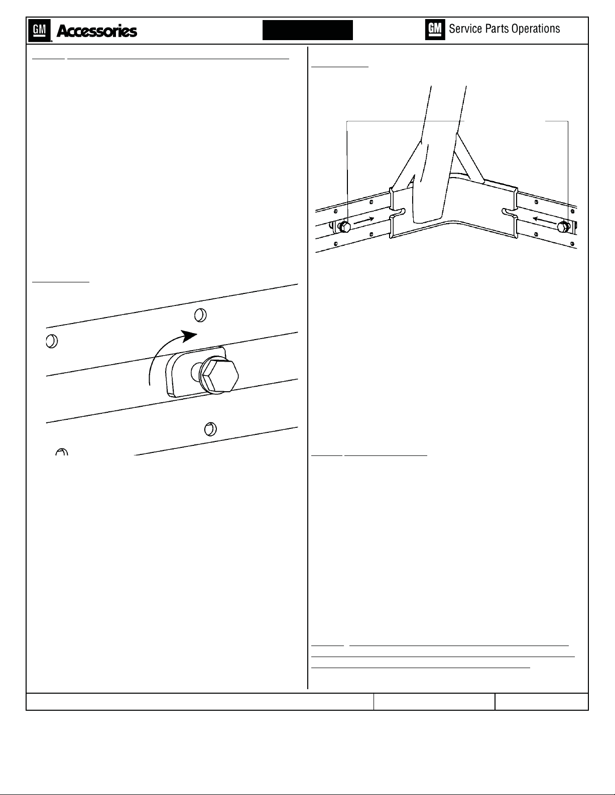
3.1. Installer les quatre écrous de la glissière en insérant
tout d’abord le côté avec le ressort dans la fente entre
les rails supérieure et inférieure des glissières de
gestion des bagages. Tourner chaque écrou d’un quart
de tour dans le sens des aiguilles d’une montre pour le
verrouiller en place. Insérer les deux écrous de longeron
dans la glissière avant (un du côté conducteur et l’autre
du côté passager), et un dans l’extrémité avant de
chacun des rails latéraux (se reporter à la Figure 10).
3.2 En commençant par le côté conducteur, monter le coin
d’ossature avant dans les unités de glissière et faire
glisser les écrous de longeron dans les fentes sur le
coin de l’ossature en s’assurant que la rondelle repose
contre la tête du boulon (se reporter à la Figure 11).
Serrer les boulons de 10 mm à un couple de 35 Nm.
Reprendre sur le côté passager.
3.3 Mettre en position une traverse (préassemblée) à travers
les deux cales de montage de coin de l’ossature, en
ajustant deux boulons à tête rectangulaire dans les
ouvertures de chaque cale de montage. Garder le
troisième boulon à tête rectangulaire à l’intérieur de la
cale de montage de chaque côté. Poser sans le serrer
un écrou autofreiné de 10 mm sur chacun des quatre
boulons à tête rectangulaire (se reporter à la Figure 8).
3.4 Pour centrer la traverse entre les deux coins de
l’ossature, mesurer une saillie de 5 ¼ po entre une
extrémité de la traverse et la cale de montage, et serrer
les quatre écrous autofreinés (se reporter à la Figure 8).
Serrer à un couple de 25 Nm.
3.5 Répéter les étapes 2.14 et 2.15 sur la traverse avant.
Étape 4 Installer les attaches
4.1 Insérer deux boulons à tête rectangulaire d’attache à
travers la fente usinée dans la fente supérieure de
chaque traverse. IMPORTANT : Les filets usinés sur les
boulons à tête rectangulaire des attaches n’ont pas la
même taille que les autres boulons à tête rectangulaire
dans l’ensemble.
4.2 Revoir l’orientation des attaches dans la Figure 9.
Insérer la clé et la faire glisser sur le corps des attaches
à travers la fente usinée dans la fente supérieure de
chaque traverse et engager le boulon à tête
rectangulaire dans le trou dans le corps de l’attache.
Attacher le bouton d’attache, faire glisser à la position
désirée et serrer fermement.
4.3 Répéter pour les trois attaches restantes.
Étape 5 Mettre le guide du propriétaire des accessoires de
gestion des bagages de caisse de camionnette dans la boîte
à gants avec le guide du propriétaire du véhicule.
FIGURE 10
FIGURE 11
RIVET-ÉCROU
FAIRE GLIS-
SER EN
PLACE ET
SERRER