manuals.online logo
Brands
  1. Home
  2. •
  3. Brands
  4. •
  5. Helios
  6. •
  7. Controllers
  8. •
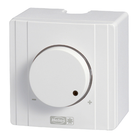
  9. Helios ESA 5 User manual

Helios ESA 5 User manual

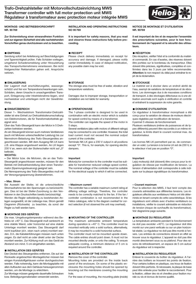
Drehzahlsteller ESA 5 und ESU 5
Electronic controllers ESA 5 and ESU 5
égulateur de vitesse ESA 5 et ESU 5
MONTAGE- UND BET IEBS-
VO SCH IFT N . 94306
Zur Sicherstellung einer einwandfreien
Funktion und zur eigenen Sicherheit
sind alle nachstehenden Vorschriften
genau durchzulesen und zu beachten.
EMPFANG
Sendung sofort bei Anlieferung auf Be-
schädigungen und Typenrichtigkeit prü-
fen. Falls Schäden vorliegen, umgehend
Schadensmeldung unter Hinzuziehung
des Transportunternehmens veranlassen.
Bei nicht fristgerechter Reklamation ge-
hen evtl. Ansprüche verloren.
EINLAGE UNG
Der Lagerort muss erschütterungsfrei,
wassergeschützt und frei von Tempera-
turschwankungen sein. Schäden, deren
Ursache in unsachgemäßem Transport,
Einlagerung oder nbetriebnahme liegen,
sind nachweisbar und unterliegen nicht
der Gewährleistung.
LIEFE WEISE
Die elektronischen Drehzahlsteller wer-
den in den folgenden Leistungsgrößen
geliefert:
ESU 5 max. Belastung 5 A
ESA 5 max. Belastung 5 A
Erforderliche Mindestlast jeweils 0,2 A.
ESU 5: Elektr. Drehzahlsteller für Unter-
putz- nstallation mit erforderlicher Dop-
peldose.
ESA 5: Elektr. Drehzahlsteller für Auf-
putz- nstallation, Hellgraues Kunststoff-
gehäuse mit Betriebsanzeigelampe im
Drehknopf. Untere Frontplatte Aluminium
eloxiert.
EINSATZBE EICH
Mit diesen Drehzahlstellern können Venti-
latoren durch Spannungsreduzierung
stufenlos drehzahlgesteuert werden. Vor-
aussetzung hierfür ist, dass die Ventilato-
ren hierzu geeignet sind. Falls diese
Eigenschaft (Drehzahlsteuerung durch
Spannungsreduzierung mit Prinzip des
Phasenanschnittes) vom Motoren-/Venti-
latoren-Hersteller nicht garantiert wird,
darf ein Einsatz nicht erfolgen.
An einem Steller können mehrere Ventila-
toren bis zum Erreichen der Nennbelast-
barkeit betrieben werden. Bei der Be-
messung ist jedoch unbedingt zu beach-
ten, dass ein Ventilator-Motor im ge-
regelten Spannungsbereich bis zum 1,3
fachen seines Nennstroms aufnehmen
INSTALLATION AND OPE ATING
INST UCTIONS NO. 94306
It is important for safety reasons, that
you read and observe these instruc-
tions fully before proceeding.
ECEIPT
Please check consignment immediately
on receipt for accuracy and damage.
f damaged, please notify carrier imme-
diately. Delay in notification may invalidate
any possible claim.
STO AGE
The storage area must be free of water,
vibration and temperature variations.
Damages due to improper storage,
transportation or installation are not liable
for warranty.
CONTENTS
There are ES.. models with following out-
puts:
ESU 5 max. load 5 Amps.
ESA 5 max. load 5 Amps.
Minimum load for both models 0.2 Amps.
ESU 5: Electronic speed controller for
flush mounted installation
. nclude the el-
ectronic control unit and an illuminated
control knob.
ESA 5: Electronic speed controller for
surface mounting. Light-grey polymer
casing with facia plate anodied alumini-
um. Also inlcude a mounting box and ca-
ble entry glands.
OPE ATION/USE
This electronic controller is for stepless
control of single phase fans within its rated
load (by voltage reduction). f a fan is not
recommended by the the supplier as
suitable for speed control on voltage re-
duction (clipping the phase) it must not
be connected.
NOTICE D’INSTALLATION ET
D’UTILISATION NO. 94306
Par mesure de sécurité, l’ensemble
des prescriptions qui suivent sont à
lire attentivement et à respecter!
ÉCEPTION
Dès réception vérifier l’état et la confor-
mité du matériel commandé. En cas d’a-
varies, faire les réclamations d’usage au-
près du transporteur.
ATTENTION: Pas de remarques à
temps, pas de recours.
STOCKAGE
Le matériel est à stocker dans un endroit
abrité de l’eau, exempt de variations de
température et de vibrations. Les dom-
mages dus à de mauvaises conditions de
transport, à des stockages défectueux
ou à une utilisation anormale sont sujets
à vérification et contrôle et entraînent la
suppression de notre garantie.
LIV AISON
Les régulateurs de vitesse encastrés et
apparents ES.., sont chacun livrés en 2
exécutions:
ESU 5 ampérage max. 5 A
ESA 5 ampérage max. 5 A
Courant minimum 0,2A.
ESU 5: Régulateur électronique pour
montage encastré avec double boîte
d’encastrement (fournie).
ESA 5: Régulateur électronique pour
montage apparent. Boîtier en plastique
gris clair avec anneau lumineux sur le
bouton. Façade intérieure en aluminium
anodisé.
DOMAINE D’UTILISATION
Les régulateurs de vitesse
ESA 5 et ESU
5
permet la régulation progressive de
ventilateurs par réduction de tension,
supposant que le ventilateur y soit ap-
proprié. Si le frabricant de mo-
teurs/ventilateurs ne peut pas garantir
cette qualité (régulation de vitesse par
réduction de tension), le commutateur ne
peut pas être utilisé.
Lors du dimensionnement il y a lieu de
tenir compte qu’un moteur de ventilateur
dans sa plage de tension régulée absor-
be jusqu’à 1,3 fois son courant nominal,
ce qui provoque, en cas de dimension-
nement trop juste, la destruction du ré-
gulateur. Une réserve est conseillée.
emarque: Les régulateurs de vitesse
Drehzahlsteller ESA 5 und ESU 5
Electronic controllers ESA 5 and ESU 5
égulateur de vitesse ESA 5 et ESU 5
kann, was bei zu knapper Drehzahlsteller-
dimensionierung zur Zerstörung des-
selben führt. Bei der Bemessung ist eine
ausreichende Reserve zu berücksichtigen.
HINWEIS: Elektronische Drehzahlsteller
können störende Motor-Brummgeräusche
im unteren Drehzahl-/Spannungsbereich
erzeugen. n geräuschrelevanten Einsatz-
fällen sind deshalb Trafo-Steuergeräte,
die keine Geräuschentwicklung verursa-
chen, einzusetzen.
ACHTUNG: Ein bestimmungsfremder
Einsatz ist nicht statthaft!
ELEKT ISCHE ANSCHLUSS
ACHTUNG: Alle Arbeiten sind im
spannungsfreien Zustand durchzu-
führen.
Der elektr. Anschluss darf nur von einer
autorisierten Elektrofachkraft durchgeführt
werden. Die einschlägigen Sicherheits-
vorschriften, Normen (VDE 0100 und VDE
0700 sowie die TAB's der EVU's und UVV)
sind einzuhalten. Ebenso ist die Montage-
und Betriebsvorschrift des Ventilators zu
beachten.
MONTAGE UNTE PUTZ
Einbau in tiefe UP-Gerätedose:
Netzspannung abschalten (auch bei
Sicherungswechsel). Mitgelieferte Ein-
baudose senkrecht in die Wand einbau-
en. Anschluss gemäß Schaltschema vor-
nehmen. Mit den Anschlussklemmen
nach unten in der Einbaudose befesti-
gen, Kombirahmen aufsetzen und Ab-
deckung mit Luftschlitzen waagerecht
aufstecken.
Kontrolllampe auf die mittleren Klem-
men aufsetzen; Nase zur Einstellwelle
gerichtet. Blende für Stellknopf aufsetzen
und mit der Kunststoffmutter befestigen.
Netzspannung einschalten. Mindestdreh-
zahl an der Justierschraube so einstellen,
dass der Lüfter auch bei Gegendruck
nach Ausfall der Netzspannung sicher
anläuft. Stellknopf auf die Welle stecken,
zum rechten Anschlag drehen und dann
gewünschte Drehzahl einstellen.
MONTAGE AUFPUTZ
Netzspannung abschalten (auch bei
Sicherungswechsel). Den mittels Feder-
ring geklemmten Drehknopf abziehen
und nach Lösen der Kunststoffmutter die
Frontblende abnehmen. Befestigungs-
schrauben lösen und den Einsatz aus
dem Sockel nehmen. Beiliegende Bohr-
schablone verwenden und den Sockel
senkrecht befestigen; Doppeldichtungs-
Anumber of fans can be controlled with
one controller up to the max. rated load.
Remember that a controlled motor may
require up to 1.3 times the Ampage of
the full speed nominal current. One
should allow a safety margin. Damage
can result if this is not observed.
NOTE: Electronic speed contollers may
cause a slight hum in the motor at low
speed/voltage which may be found
disturbing. For noise critical applications
we recommend the use of a transformer
controller.
ATTENTION: The unit may only be
used for its intended purpose.
ELECT ICAL CONNECTION
ATTENTION: All work must be carried
out with the equipment fully isolated
from the power supply.
All electrical connections are to be carried
out in accordance with the relevant wiring
diagram and are only to be carried out by
a qualified electrician. All relevant safety
regulations, national standards and norms
are to be adhered to. The nstallation and
Operation nstructions for the fans are
also to be observed.
FLUSH MOUNTED INSTALLATION
Installation in deep flush housing:
Disconnect mains supply (also when re-
place the fuse). Plaster enclosed wall
box vertically into the wall. Connect
speed controller according to the wiring
diagram. Fasten it in the wall box, termi-
nals downwards, fix cover frame and
cover sheet with ventiducts horizontally.
Put indicator light on medium terminals.
Tappet towards setting shaft. Fix facepla-
te for switch and fasten it with nut. Turn
shaft clockwise until it stops. Switch on
mains supply. To ensure that the motor
will run again after a disconnection of the
mains supply adjust the setting screw to
the minimum r.p.m.
Put setting knob on the shaft and turn it
clockwise until it stops. Then fix the re-
quested r.p.m.
SU FACE MOUNTED INSTALLATION
Disconnect mains supply (also when
changing the fuse). Pull off the adjusting
knob fixed by means of a spring from the
shaft, loosen nut and remove hood.
Loosen fastening screws and take the
speed controller from the base. Use box
cover as drill template and fasten the
base vertically. Double joint connection
downwards. Lead cables through the
électroniques sont susceptibles de créer
des bruits secondaires perturbant l’envi-
ronnement, en cas d’utilisation en petite
vitesse ou en basse tension. Dans les in-
stallations où le niveau sonore est un
critère déterminant, il est préférable de
monter des régulateurs à transformateurs
ne produisant aucun bruit.
ATTENTION: Il n’est pas permis d’utili-
ser ces appareils pour d’autres fonc-
tions!
B ANCHEMENT ÉLECT IQUE
ATTENTION: Tous les travaux doivent
être effectués hors tension.
Le branchement électrique est à réaliser
selon le schéma de connexion correspon-
dant. l doit être effectué par un électricien
qualifié. Les consignes de sécurité ainsi
que les normes standards nationales
doivent être respectées. l est aussi impé-
ratif de respecter les indications des in-
structions d’installation.
MONTAGE ENCAST E
Montage en boîte d’encastrement:
Couper l’alimentation (même pour un
remplacement de fusible). Mettre en pla-
ce la boîte d’encastrement (fournie) ver-
ticalement dans le mur. Procéder au rac-
cordement électrique selon le schéma de
branchement. Montage de l’ensemble,
bornier vers le bas. Mise en place du ca-
dre d’habillage et du cache (ouvertures
de ventilation horizontales).
Mise en place du voyant sur les deux
bornes centrales, bossage orienté vers
l’axe; Mettre le cadre en place et le fixer
avec l’écrou. Tourner l’axe vers la droite
en butée. Remettre sous tension. Régler
la vitesse minimale à l’aide de la vis d’a-
justage pour permettre un démarrage à
contre-pression en cas de coupure de
courant. Emboîter le bouton de réglage
sur l’axe, tourner vers la droite en butée
et régler la vitesse.
MONTAGE APPA ENT
Couper l’alimentation (même pour un
remplacement de fusible). Retirer le bou-
ton de réglage maintenu sur l’axe par un
ressort anneau. Dévisser l’écrou et retirer
le boîtier; Utiliser le gabarit de perçage et
fixer le boîtier verticalement, les deux
presse-étoupes vers le bas. Pour l’intro-
duction du câble, utiliser les presse-étou-
pes joints ou cacher l’ouverture du
Drehzahlsteller ESA 5 und ESU 5
Electronic controllers ESA 5 and ESU 5
égulateur de vitesse ESA 5 et ESU 5
stutzen müssen nach unten zeigen. Zur
Einführung des Kabels beigelegte Kabel-
durchführungen je nach Bedarf ins Ge-
häuse einsetzen oder den Gehäuse-
durchbruch mittels beiliegendem Ver-
schlussstück abdecken. Gehäuse mittels
beiliegender Schrauben und Dübel befe-
stigen. Anschluss gemäß Schaubild.
Drehzahlsteller mit Anschlussklemmen
nach oben in Gehäuse einschrauben.
Frontblende aufstecken und Mutter an-
ziehen. Welle zum rechten Anschlag dre-
hen. Stellknopf mit Federring auf die
Welle stecken. Mindestdrehzahl an der
Justierschraube so einstellen, dass der
Lüfter auch bei Gegendruck nach Ausfall
der Netzspannung sicher anläuft. (Siehe
Absatz 2 „Montage Unterputz“).
ABSICHE UNG
Die Geräte sind mit jeweils zwei Fein-
sicherungen (5 x 20 mm) ausgerüstet:
ESA 5 F 6,3 H, 250 V
ESU 5 F 6,3 H, 250 V
Klemme 1, die bei Betrieb immer die volle
Spannung hat (Anschluss von elek-
trischer Verschlussklappe, Kontroll-
lampe), ist mit abgesichert. Die Gesamt-
belastung von Klemme 1 u. darf
den Nennwert (5 A) nicht übersteigen.
TECHNISCHE DATEN
Nennspannung: 230 V, 50 Hz
Max. Belastung: 4.3 – 5 A (T 40 E)
Mind. Belastung: 0,2 A
Umgebungstemperatur: 0° bis + 35°C
Überlastschutz: Temperaturbegrenzer
Schutzart: ESA 5 P 44
Maße ESA 5: B 84 x H 170 x T 66
Schutzart: ESU 5 P 20
Maße ESU 5: B 81 x H 170 x T 66
HINWEIS: m professionellen Anwen-
dungsbereich kann der Nennstrom 5 A
betragen.
WÄ MEABLEITUNG
Die angegebene max. Anschlussleistung
gilt für den Einbau in Massivwände. Bei
geringerer Wärmeableitung, z.B. in Hohl-
wänden, Holzkonstruktionen, Gipsplatten
etc. sowie bei gegenseitiger Erwärmung
mehrerer elektronischer Geräte, muss
die max. Anschlussleistung um 20% re-
duziert werden. Die Nennleistungsan-
gaben gelten für eine Umgebungstemp-
eratur von max. 35 °C. Bei erhöhter Um-
gebungstemperatur ist eine Reduktion
der Nennleistung um 20% pro 10 °K
Temperaturanstieg notwendig.
joint connection and connect at the
speed controller according to the wiring
diagram with the terminals downwards.
Secure the speed controller and turn the
operating shaft to the right limit stop.
Switch on mains supply. To ensure that
the fan will run again after a disconnec-
tion of the mains supply, adjust the set-
ting crew to the minimum r.p.m.
SAFETY FUSE
The units come with the following fuses
(5 x 20 mm):
ESA 5 F 6,3 H, 250 V
ESU 5 F 6,3 H, 250 V
Terminal 1, which always carries the ma-
ximum voltage is also protected. The total
Ampage of terminals 1 and must
not exceed the rated max. Amps.
TECHNICAL DATA
Current at 230 V, 50 Hz
Max. load 4.3 – 5 A (T 40 E)
Min. load 0.2 A
Ambient temperature 0° to + 35°C
Overload prote. Temperature limitation
Protection to ESA 5 P 44
Dimensions B 84 x H 170 x T 66
Protection to ESU 5 P 20
Dimensions B 84 x H 170 x T 66
NOTE: n the professionel field of appli-
cation, the rated current can be 5 A.
HEAT DISSIPATION
The indicated maximum loads hve been
calculated on the basis of installation of
the unit in solid walls.
Warning: When installing in cavity walls,
wooden partitions or other poor heat
transmitters a derating factor of 20% has
to be applied to the maximum loading.
This 20% erating factor also has to be
applied if several electronic devices are
installed side by side due to the combined
heat generation. Max. temperature of en-
vironment 35° C.
boîtier à l’aide de l’obturateur joint. Fixer
le boîtier à l’aide des vis et chevilles join-
tes. Raccorder selon le schéma. Visser le
régulateur dans son boîtier, bornes de
raccordement vers le haut. Remettre le
boîtier en place et bloquer l’écrou.
Tourner l’axe en butée vers la droite.
Régler la vitesse minimale à l’aide de la
vis d’ajustage pour permettre un démar-
rage à contre-pression en cas de coupu-
re de courant. (voir paragraphe 2
„Montage encastré“).
P OTECTION
Les appareils sont équipés de fusibles
(5 x 20 mm):
ESA 5 F 6,3 H, 250 V
ESU 5 F 6,3 H, 250 V
La borne 1, qui (pendant la marche) reste
toujours sous tension pleine, est égale-
ment protégée. La borne 1 peut servir de
branchement pour volets électro-magne-
tiques ou pour une lampe témoin. La
charge maximale des bornes 1 et
ne doit pas dépasser la valeur nominale
du régulateur (5 A).

INDICATIONS TECHNIQUES
Tension nominale 230 V, 50 Hz
Ampérage max. 4.3 – 5 A (T 40 E)
Ampérage min. d’utilisation 0,2 A
température de l'air ambiant
0° aller jusqu'à + 35°C
Protection ESA 5 P 44
Dimensions B 84 x H 170 x T 66
Protection ESU 5 P 20
Dimensions B 84 x H 170 x T 66
NOTA: Dans le cas d’une utilisation en
contexte professionnel, le courant nomi-
nal peut s’élever à 5 A.
DISSIPATION DE LA CHALEU
La puissance maxi d’utilisation est valable
pour le montage dans des murs massif.
Cette puissance doit être réduite de 20%
dans le cas d’emploi dans des murs
creux, construction bois, platres rigides,
combinaison de plusieurs appareils ou
tout autre cas empêchant une dissipation
normale de la chaleur. Température max.
d’environnement 35 °C. Au dessus de
cette T° réduire de 20% par tranche de
10 K.
ACCESSOI ES, APPA EILS DE
TEMPO ISATION ET DE ÉGULATION
L’utilisation d’accessoires qui ne sont
pas directement offerts ou conseillés par
Helios n’est pas autorisée. Les domma-
ges éventuels entraînent la suppression
de notre garantie.
DEMANDE DE GA ANTIE –
ÉSE VES DU CONST UCTEU
En cas de non-respect des indications
précédentes, toute demande de rempla-
cement ou de réparation à titre gratuit
sera déclinée. l en sera de même pour
toute implication de responsabilité du fa-
bricant.
ÉGLEMENTATIONS – NO MES
Si la notice d’installation et d’utilisation
est observée, nos produits correspondent
aux normes et réglementations interna-
tionales.
ACCESSO IES, SWITCHES AND
CONT OLLING DEVICES
The use of accessories not offered or re-
commended by Helios is not permitted.
Any potential damage claims become
invalid.
WA ANTY – EXCLUSION OF
LIABILITY
f the preceding instructions are not ob-
served all warranty claims are excluded.
The Helios warranty is limited to the
material and workmanship of the product.
CE TIFICATES
The products are manufactured in
compliance with applicable European
standards and regulations.
ZUBEHÖ , SCHALT- UND
STEUE ELEMENTE
Der Gebrauch von Zubehörteilen, die
nicht von Helios empfohlen oder ange-
boten werden, ist nicht statthaft. Eventuell
auftretende Schäden unterliegen nicht
der Gewährleistung.
GA ANTIEANSP ÜCHE –
HAFTUNGSAUSSCHLUSS
Wenn die vorausgehenden Ausführungen
nicht beachtet werden, entfällt unsere
Gewährleistung und Behandlung auf Ku-
lanz. Gleiches gilt für abgeleitete Haftungs-
ansprüche an den Hersteller.
VO SCH IFTEN – ICHTLINIEN
Bei ordnungsgemäßer nstallation und
bestimmungsgemäßem Betrieb entspricht
das Gerät den zum Zeitpunkt seiner Her-
stellung gültigen Vorschriften und Richt-
linien CE.
Druckschrift-Nr. 94306/ 04.09
Drehzahlsteller ESA 5 und ESU 5
Electronic controllers ESA 5 and ESU 5
égulateur de vitesse ESA 5 et ESU 5
Verschlußklappe
shutter
volet de fermeture
Kontrollampe
lamp
voyant de
contrôle
12
34
N
ESA/U 5
L
N
PE
M
1~
Schaltschema
Wiring Diagram
Schéma de branchement
SS-165
D HEL OS Ventilatoren GmbH & Co. · Lupfenstraße 8 · 78056 VS-Schwenningen
CH HEL OS Ventilatoren AG · Steinackerstraße 36 · 8902 Urdorf-Zürich
A HEL OS Ventilatoren · Postfach 854 · Siemensstraße 15 · 6023 nnsbruck
F HEL OS Ventilateurs · Le Carré des Aviateurs · 157 av. Charles Floquet ·
93155 Le Blanc Mesnil Cedex
GB HEL OS Ventilation Systems Ltd. · 5 Crown Gate · Wyncolls Road ·
Severalls ndustrial Park · Colchester · Essex · CO4 9HZ
Sockel
base/socle
Frontblende
hood/bandeau
Justierschraube
setting screw/
vis de réglage
Sicherung
fuse/fusible
Mutter
nut/écrou
Stellknopf
setting knob/
bouton poussoir
Einbaudose
flush-mounting
socket/
Kombirahmen
combined border/
unie bordure
Abdeckung mit
Luftschlitzen/
coping w. airlouvre/
couvercle protect.
Justierschraube
Setting screw/
vis de réglage
Sicherung
Fuse/fusible
Stellknopf
Setting knob/
bouton poussoir
Kontrolllampe
pilot lamp/
voyant
C-Scheibe
C-disc/C-disque
Leistungsderating
derating curve

This manual suits for next models

1

Other Helios Controllers manuals

Helios KWL-BE User manual

Helios

Helios KWL-BE User manual

Helios WS 1,5 User manual

Helios

Helios WS 1,5 User manual

Helios EDR Owner's manual

Helios

Helios EDR Owner's manual

Helios KWL 45 BEU User manual

Helios

Helios KWL 45 BEU User manual

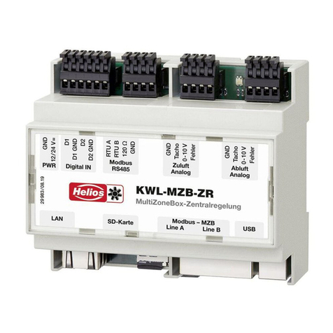
Helios KWL-MZB-ZR User manual

Helios

Helios KWL-MZB-ZR User manual

Helios MWS User manual

Helios

Helios MWS User manual

Helios ESA User manual

Helios

Helios ESA User manual

Helios TSD 0,8 User manual

Helios

Helios TSD 0,8 User manual

Helios 5 Target User manual

Helios

Helios 5 Target User manual

Helios ETR User manual

Helios

Helios ETR User manual

Helios AIR1-BE TOUCH User manual

Helios

Helios AIR1-BE TOUCH User manual

Helios KWL-BEC User manual

Helios

Helios KWL-BEC User manual

Helios 90 770 User manual

Helios

Helios 90 770 User manual

Helios KWL-BE Touch User manual

Helios

Helios KWL-BE Touch User manual

Helios ESA User manual

Helios

Helios ESA User manual

Helios ESE 2,5 Service manual

Helios

Helios ESE 2,5 Service manual

Helios AIR1-BE ECO User manual

Helios

Helios AIR1-BE ECO User manual

Helios EDR Owner's manual

Helios

Helios EDR Owner's manual

Helios KWL-BE Eco User manual

Helios

Helios KWL-BE Eco User manual

Helios KWL-MZB-BE User manual

Helios

Helios KWL-MZB-BE User manual

Helios PA Series User manual

Helios

Helios PA Series User manual

Helios TSD 0,8-11 User manual

Helios

Helios TSD 0,8-11 User manual

Helios ESD User manual

Helios

Helios ESD User manual

Helios TDS 0,8 User manual

Helios

Helios TDS 0,8 User manual

Popular Controllers manuals by other brands

Light O Rama Pixie2D user manual

Light O Rama

Light O Rama Pixie2D user manual

Prolon C1000 Series Hardware guide

Prolon

Prolon C1000 Series Hardware guide

Wet Sounds RF-RGB-MC V2 owner's manual

Wet Sounds

Wet Sounds RF-RGB-MC V2 owner's manual

Xylem HYDROVAR HV 2.015 operating instructions

Xylem

Xylem HYDROVAR HV 2.015 operating instructions

Wilkerson R30 Series Installation & service instructions

Wilkerson

Wilkerson R30 Series Installation & service instructions

GESTRA NRR 2-40 installation instructions

GESTRA

GESTRA NRR 2-40 installation instructions

EAE UD105 product manual

EAE

EAE UD105 product manual

Trinamic TMC428 Application note

Trinamic

Trinamic TMC428 Application note

Bosch Rexroth CKL Series Commissioning

Bosch

Bosch Rexroth CKL Series Commissioning

Orno OR-SA-1715 Operating and installation instructions

Orno

Orno OR-SA-1715 Operating and installation instructions

BERMAD BIC-F Operation manual

BERMAD

BERMAD BIC-F Operation manual

ICT Protege GX DIN Rail System Controller quick start guide

ICT

ICT Protege GX DIN Rail System Controller quick start guide

Micronix MMC-10 Series Reference manual

Micronix

Micronix MMC-10 Series Reference manual

Cooper Power Tools ARS-310/5 product manual

Cooper Power Tools

Cooper Power Tools ARS-310/5 product manual

Hanna Instruments EC Series instruction manual

Hanna Instruments

Hanna Instruments EC Series instruction manual

Cypress UNIVERSAL CAPSENSE quick start guide

Cypress

Cypress UNIVERSAL CAPSENSE quick start guide

REXROTH IndraControl L25 Series Project planning manual

REXROTH

REXROTH IndraControl L25 Series Project planning manual

RKC INSTRUMENT CB Series Connection manual

RKC INSTRUMENT

RKC INSTRUMENT CB Series Connection manual

manuals.online logo
manuals.online logoBrands
  • About & Mission
  • Contact us
  • Privacy Policy
  • Terms and Conditions

Copyright 2025 Manuals.Online. All Rights Reserved.