Helios KWL-MZB-BE User manual

Helios Ventilatoren
MONTAGE- UND BETRIEBSVORSCHRIFT
INSTALLATION AND OPERATING INSTRUCTIONS
Bedienelement Eco
Control Element Eco
KWL-MZB-BE
für die MultiZoneBox KWL-MZB
for the MultiZoneBox KWL-MZB
DE
EN

MONTAGE- UND BETRIEBSVORSCHRIFT
Inhaltsverzeichnis
KAPITEL 1 ALLGEMEINE HINWEISE............................................... Seite 1
1.0 Allgemeine Informationen ................................................... Seite 1
1.1 Warn- und Sicherheitshinweise. . . . . . . . . . . . . . . . . . . . . . . . . . . . . . . . . . . . . . . . . . . . . . . Seite 1
1.2 Garantieansprüche – Haftungsansprüche....................................... Seite 1
1.3 Vorschriften – Richtlinien ................................................... Seite 1
1.4 Sendungsannahme ....................................................... Seite 1
1.5 Einlagerung ............................................................. Seite 1
1.6 Bestimmungsgemäße Verwendung ........................................... Seite 2
1.7 Entsorgung ............................................................. Seite 2
1.8 Funktionen .............................................................. Seite 2
KAPITEL 2 MONTAGE .......................................................... Seite 3
2.0 Technische Daten ........................................................ Seite 3
2.1 Schaltplan .............................................................. Seite 3
DEUTSCH

1.0 Allgemeine Informationen
Zur Sicherstellung einer einwandfreien Funktion und zur eigenen Sicherheit sind
alle nachstehenden Vorschriften genau durchzulesen und zu beachten. National
einschlägige Normen, Sicherheitsbestimmungen und Vorschriften (z.B. DIN EN
VDE 0100) sowie die technischen Anschlussbestimmungen (TAB) des Elektrizi-
tätsversorgungsunternehmens (EVU) sind unbedingt zu beachten und anzuwen-
den.
Die Montage- und Betriebsvorschrift ist als Referenz aufzubewahren. Nach der
Endmontage muss dem Betreiber (Mieter/Eigentümer) das Dokument ausgehän-
digt werden.
1.1 Warn- und Sicherheitshinweise
Nebenstehendes Symbol ist ein sicherheitstechnischer Warnhinweis. Alle
Sicherheitsvorschriften bzw. Symbole müssen unbedingt beachtet werden,
damit jegliche Gefahrensituation vermieden wird.
1.2 Garantieansprüche – Haftungsausschluss
Zur Wahrung der Gewährleistungs- und Haftungsansprüche sind zwingend nach-
folgende Ausführungen zu beachten:
−Umsetzung nach Montage- und Betriebsvorschrift des Gerätes.
−Die Verwendung von Zubehörteilen, die nicht von Helios Ventilatoren freigege-
ben, empfohlen oder angeboten werden, ist nicht zulässig. Eventuell auftretende
Schäden unterliegen nicht der Gewährleistung.
Wenn diese Ausführungen nicht beachtet werden, entfällt die Gewährleistung.
Gleiches gilt für Haftungsansprüche an den Hersteller.
1.3 Vorschriften – Richtlinien
Bei ordnungsgemäßer Installation und bestimmungsgemäßem Betrieb ent-
spricht das Gerät den zum Zeitpunkt seiner Herstellung gültigen Vorschriften und
CE-Richtlinien.
1.4 Sendungsannahme
Die Sendung ist sofort bei Anlieferung auf Beschädigungen und Typenrichtigkeit
zu prüfen. Falls Schäden vorliegen, unverzüglich Schadensmeldung unter Hinzu-
ziehung des Transportunternehmens veranlassen. Bei nicht fristgerechter Rekla-
mation gehen evtl. Ansprüche verloren.
1.5 Einlagerung
Das Gerät ist in geschützten Räumen trocken und staubfrei zu lagern. Bei Einlage-
rung über einen längeren Zeitraum sind zur Verhinderung schädlicher Einwirkun-
gen folgende Maßnahmen zu treffen: Schutz durch trockene, luft- und staubdichte
Verpackung (Kunststoffbeutel mit Trockenmittel und Feuchtigkeitsindikatoren).
Der Lagerort muss wassergeschützt und frei von übermäßigen Temperatur-
schwankungen sein. Schäden, deren Ursprung in unsachgemäßem Transport,
unsachgemäßer Einlagerung oder Inbetriebnahme liegen, sind nachweisbar und
unterliegen nicht der Gewährleistung.
KAPITEL 1
ALLGEMEINE
HINWEISE
m
DE
1
Bedienelement - KWL-MZB-BE
Montage- und Betriebsvorschrift

1.6 Bestimmungsgemäße Verwendung
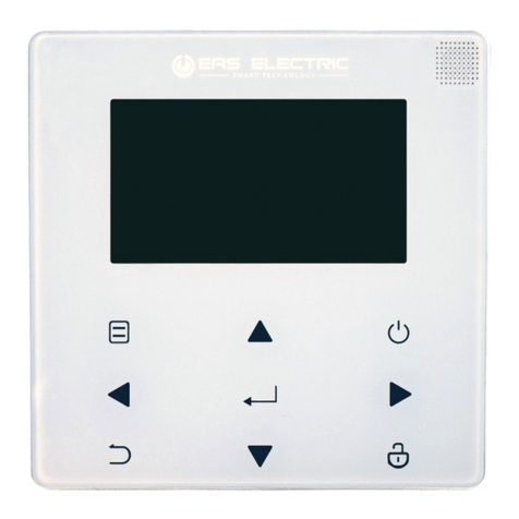
Das Bedienelement ist zur Steuerung der MultiZoneBox KWL-MZB bestimmt. Es
ist kein gebrauchsfertiges Produkt und darf erst in Betrieb genommen werden
nachdem die raumlufttechnische Anlage ordnungsgemäß eingebaut und ange-
schlossen wurde. Das Bedienelement ist zur Unterputzmontage in eine Leerdose
Durchmesser 68 mm bestimmt.
Ein bestimmungsfremder Einsatz ist nicht zulässig!
1.7 Entsorgung
Ein autorisierter Fachbetrieb für die Abfallbehandlung muss das Gerät oder die
einzelnen Komponenten entsorgen. Der beauftragte Auftragnehmer muss sicher-
stellen dass:
−die Komponenten nach Materialarten getrennt werden.
−die verwendeten Betriebsstoffe nach ihren jeweiligen Eigenschaften sortiert und
getrennt werden.
1.8 Funktionen
Über das Bedienelement können die folgenden Funktionen eingestellt werden:
• Automatikbetrieb
• Manueller Betrieb
• Lüftungsstufe 1-3
• Grundlüftung
• AUS
Automatikbetrieb (nur mit optionalem Sensor in MZB möglich)
Durch drücken der Taste wird der Automatikbetrieb aktiviert und durch die
nebenstehende LED angezeigt. Das Lüftungsgerät befindet sich im Automatikbe-
trieb, d.h. die Lüftungsstufen werden automatisch anhand der Luftqualität gesteu-
ert. Die aktuelle Lüfterstufe wird durch die LEDs angezeigt.
Durch Drücken der Pfeiltasten kann die Empfindlichkeit (gering/mittel/hoch)
der Steuerung verändert werden. Die LEDs der Lüftungsstufen repräsentieren
hierbei die gewählte Einstellung an („1“ niedrig – „3“ hoch). Nach kurzer Zeit erlö-
schen diese wieder, können jedoch durch kurzes Drücken der Pfeiltaste zur
Abfrage der gewählten Einstellung, wieder aktiviert werden.
Manueller Betrieb
Der manuelle Betrieb wird durch Drücken der Taste M aktiviert und durch die
nebenstehende LED angezeigt. Das Lüftungsgerät befindet sich nun im manuellen
Betrieb.
Lüftungsstufe 3
Lüftungsstufe 2
Lüftungsstufe 1
DE
2
Bedienelement - KWL-MZB-BE
Montage- und Betriebsvorschrift

Mit den beiden Pfeiltasten können die einzelnen Lüftungsstufen ausgewählt
und fest eingestellt werden. Die LEDs zeigen die ausgewählte Lüftungsstufe an.
Bei blinkender Lüftungsstufe 1 ist die Grundlüftung ausgewählt. Durch Drücken
der Pfeiltaste mit Pfeil nach unten bis keine der drei LEDs mehr leuchtet oder
blinkt, ist das Gerät ausgeschaltet (nur bei deaktivierter Grundlüftung möglich).
Grundlüftung
Blinkt die LED der Lüftungsstufe 1 ist die Grundlüftung aktiviert. Die Grund-
lüftung gewährleistet einen minimalen Luftwechsel der dem Feuchteschutz dient.
AUS (nur bei deaktivierter Grundlüftung möglich)
Bei Auswahl der Betriebsart „Aus“ werden die Klappen der MZB geschlossen und
so die Luft Ab-Zufuhr in die Nutzungseinheit unterbrochen.
Fehlermeldung
Die Fehlermeldung wird bei einer Betriebsstörung des Gerätes durch Leuchten
der LED angezeigt. Wird eine Fehlermeldung angezeigt, umgehend den Service
informieren.
Fehlerliste MZB-BE
Fehler-
nummer
Blinkcode Kommentar
0 - Kein Fehler
1 2x Blinken + Pause Fehler Systemspeicher. Parameterdaten konnten
nicht geladen werden.
3 6x Blinken + Pause Fehler Kommunikation Sensor intern. Eine Kommu-
nikation mit dem konfigurierten Sensor konnte nicht
hergestellt werden.
4 8x Blinken + Pause Fehler Kommunikation. Eine Kommunikation zwi-
schen MZB und BE konnte nicht hergestellt werden.
2.0 Technische Daten
KWL-MZB-BE für Unterputzmontage
Spannung 12 V
Betriebsstufen 4 (Lüftungsstufe 1-3, Grundlüftung/Aus)
Steuerleitung J-Y(St) 2 x 2 x 0,6
Schutzart IP20
Maße (B x H x T) mm 80 x 80 x 10
Anforderungen Aufstellraum 0-55°C <95% r.F (nicht kondensierend)
Gewicht 54 g
2.1 Schaltplan
m Lebensgefahr durch elektrischen Schlag.
Die Elektroanschlüsse und Inbetriebnahme sowie Installationsarbeiten dürfen nur von
autorisierten Elektrofachkräften ausgeführt werden.
Bedienelement gemäß Anschlussplan anschließen.
KAPITEL 2
MONTAGE
m GEFAHR
DE
3
Bedienelement - KWL-MZB-BE
Montage- und Betriebsvorschrift

DE
4
Bedienelement - KWL-MZB-BE
Montage- und Betriebsvorschrift
85464 001 SS-1202 30.05.18 S.1
LH LH
Druck-
sensor
Druck-
sensor
Zuluft Abluft
USB (B)
12
34
56
78
9 10
RJ45
RJ45
1
2
1
2
3
Potentialfreier Kontakt
(bis 230V / 5A)
RD
BN
BK
BK
BU
YE
RD
BN
BK
BK
BU
YE
Stellmotor
Klappe Zuluft
Stellmotor
Klappe Abluft
12
34
56
78
KWL-MZB-VOC-F
Art.-Nr.: 4216
Sicherung
T3,15A
L
N
PE
1
81
8
A
B
1
1
2
3
4
A
M
!
Vorderseite Rückseite
1 2 3 4
Vorderseite Rückseite
J-Y(St) 2x2x0,6
(max. 100m)
8
1oben
1: 12V
3: RS485 A
5: RS485 B
7: 12V BDE
9: GND BDE
2: Eingang 1 Digital/0-10V
4: Eingang 2 Digital/0-10V
6: Eingang 3 Digital/0-10V
8: T-Fühler PT1000/KTY81-110
10: T-Fühler PT1000/KTY81-110
3 x 1,5mm²
Konfiguration
des Geräts
Schlauch innen: 2mm
Achtung!
Pinbelegung BET und
BE unterschiedlich,
entsprechend anpassen
2
34
56
78
910
KWL-MZB ...
KWL-MZB-BET, Art.-Nr.: 4214
KWL-MZB-BE, Art.-Nr.: 4213
Helios
KWL-MZB-F
Art.-Nr.: 4250
oder
D
S.1
E
F
S.2 S.3

DE
5
Bedienelement - KWL-MZB-BE
Montage- und Betriebsvorschrift

INSTALLATION AND OPERATING INSTRUCTIONS
Table of Contents
CHAPTER 1 GENERAL INFORMATION .............................................Page 1
1.0 General information .......................................................Page 1
1.1 Warning and safety instructions ..............................................Page 1
1.2 Warranty and liability claims .................................................Page 1
1.3 Regulations – Guidelines ...................................................Page 1
1.4 Receipt ................................................................Page 1
1.5 Storage ................................................................Page 1
1.6 Intended use ............................................................ Page 2
1.7 Functions ...............................................................Page 2
CHAPTER 2 INSTALLATION .....................................................Page 3
2.0 Technical data ...........................................................Page 3
2.1 Wiring diagram...........................................................Page 3
ENGLISH

1.0 General information
In order to ensure complete and effective operation and for your own safety, all
of the following instructions should be read carefully and observed. The relevant
national standards, safety regulations and instructions (e.g. DIN EN VDE 0100) as
well as the technical connection conditions of the energy supply company must
be observed and applied.
Keep the Installation and Operating Instructions as a reference. After the final
assembly the document must be handed out to the operator (tenant/owner).
1.1 Warning and safety instructions
The adjacent symbol is a safety-relevant warning symbol. All safety regula-
tions and/or symbols must be absolutely adhered to, so that any dangerous
situation is avoided.
1.2 Warranty and liability claims
In order to safeguard the guarantee and liability claims of the customer, the follo-
wing information must be observed:
– Implementation according to “unit” Installation and Operating Instructions.
– The use of accessories, which are not approved, recommended or offered by
Helios, is not permissible. Any damages are excluded from the guarantee.
If these instructions are not observed, all warranty claims are excluded. This also
applies to any liability claims extended to the manufacturer.
1.3 Regulations – Guidelines
If the product is installed correctly and used to its intended purpose, it conforms to
all applicable regulations and CE guidelines at its date of manufacture.
1.4 Receipt
Please check delivery immediately on receipt for accuracy and damage. If dama-
ged, please notify the carrier immediately. In case of delayed notification, any pos-
sible claim may be void.
1.5 Storage
When storing for a prolonged time, the following steps are to be taken to avoid
damaging influences: Protection by dry, air-dustproof packing (plastic bags with
drying agent and moisture indicators). The storage place must be waterproof,
vibration-free and free of temperature variations. Damages due to improper trans-
portation, storage or commissioning must be verified and are not liable for war-
ranty.
CHAPTER 1
GENERAL
INFORMATION
m
EN
1
Control element - KWL-MZB-BE
Installation and Operating Instructions

1.6 Intended use
The control element is intended for controlling the MultiZoneBox KWL-MZB. It is
not a ready-to-use product and it may only be operated once the ventilation sys-
tem has been properly installed and connected. The comfort controller is designed
for flush mounting in an empty socket with a diameter of 68 mm.
Any use other than the intended use is prohibited
1.7 Disposal
An authorised specialist waste processing company must dispose of the unit or
the individual components. The appointed contractor must ensure that:
– the components are separated according to material types.
– the used operating materials are sorted and separated according to their res-
pective properties.
1.8 Functions
The following functions can be set using the control element:
• Automatic operation
• Manual operation
• Ventilation stage 1-3
• Basic Ventilation
• OFF
Automatic operation (only possible with optional sensor in MZB)
When the key is pressed, automatic operation is activated and displayed by
the LED next to the key. The ventilation unit is in automatic operation, i.e. the
ventilation stages are automatically controlled based on the air quality. The LEDs
display the current stage.
The sensitivity (low/medium/high) of the control system can be changed by pres-
sing the keys. The ventilation stages LEDs hereby display the selected
setting („1“ low - „3“ high). After a short time the LEDs are turned off, by briefly
pressing the keysthe LEDs are reactivated and display the selected setting.
Manual operation
Manual operation is activated by pressing the key M and displayed by the LED
next to the key. The ventilation unit is in manual operation now.
The individual ventilation stages can be selected and fixed with the keys.
EN
2
Control element - KWL-MZB-BE
Installation and Operating Instructions
Automatic
Manual
Error message
Ventilation stage 1
Ventilation stage 2
Ventilation stage 3

The LEDs display the selected ventilation stage. If ventilation stage 1 is flashing,
basic ventilation is selected. If the key pointing downwards is pressed until
none of the three LEDs is lit up or flashing, the unit is deactivated (only possible
when basic ventilation is deactivated).
Basic ventilation
If ventilation stage 1 is flashing, basic ventilation is active. Basic ventilation
ensures a minimum air exchange which serves as moisture protection.
OFF (only possible when basic ventilation is deactivated)
When „Off“ mode is selected, the MZB dampers will be closed and the air dischar-
ge/supply to the service unit will be interrupted.
Error message
The error message shall be displayed in case of a unit operating error by lighting
up the LED. If an error message is displayed, promptly inform the service depart-
ment.
Error list MZB-BE
Error
number
Flash code Description
0 - No error
1 2x flashing + pause Error system memory. Unable to load Parameter
data.
3 6x flashing + pause Error communication internal sensor.
Unable to set up communication with configured
sensor.
4 8x flashing + pause Error communication. Unable to set up communicati-
on between MZB and BE.
2.0 Technical data
KWL-MZB-BE for flush-mounted installation
Voltage 12 V
Operating stages 4 (ventilation stage 1-3, basic ventilation/off)
Control line J-Y(St) 2 x 2 x 0.6
Protection rating IP20
Dim. (W x H x D) mm 80 x 80 x 10
Ambient temperature / humidity 0-55°C <95% RH (none condensing)
Weight 54 g
2.1 Wiring diagram
m Danger to life through electric shock.
The electrical connection and maintenance, as well as installation work, must only
be carried out by a qualified electrician.
Connect control element according to wiring diagram.
CHAPTER 2
INSTALLATION
m DANGER
EN
3
Control element - KWL-MZB-BE
Installation and Operating Instructions

EN
4
Control element - KWL-MZB-BE
Installation and Operating Instructions
85464 001 SS-1202 30.05.18 S.2
LH LH
Pressure
sensor
Pressure
sensor
Supply air Extract air
USB (B)
12
34
56
78
9 10
RJ45
RJ45
1
2
1
2
3
Potential-free contact
(up to 230V / 5A)
RD
BN
BK
BK
BU
YE
RD
BN
BK
BK
BU
YE
Actuator flap
supply air
Actuator flap
extract air
12
34
56
78
KWL-MZB-VOC-F
Item No 4216
fuse
T3,15A
L
N
PE
1
81
8
A
B
1
1
2
3
4
A
M
!
Front Back
1 2 3 4
Front Back
J-Y(St) 2x2x0,6
(max. 100m)
8
1top
1: 12V
3: RS485 A
5: RS485 B
7: 12V BDE
9: GND BDE
2: Input 1 Digital/0-10V
4: Input 2 Digital/0-10V
6: Input 3 Digital/0-10V
8: T sensor PT1000/KTY81-110
10: T sensor PT1000/KTY81-110
3 x 1,5mm²
Configuration
of the device
Hose inside: 2mm
Attention!
Pin assignment BET and
BE different,
adjust accordingly
2
34
56
78
910
KWL-MZB ...
KWL-MZB-BET, Item No 4214
KWL-MZB-BE, Item No 4213
Helios
KWL-MZB-F
Item No 4250
or

EN
5
Control element - KWL-MZB-BE
Installation and Operating Instructions

EN
Control element - KWL-MZB-BE
Installation and Operating Instructions
6

EN
Control element - KWL-MZB-BE
Installation and Operating Instructions
7

Service und Information
DHELIOS Ventilatoren GmbH + Co KG · Lupfenstraße 8 · 78056 VS-Schwenningen FHELIOS Ventilateurs · Le Carré des Aviateurs · 157 avenue Charles Floquet · 93155 Le Blanc Mesnil Cedex
CH HELIOS Ventilatoren AG · Tannstr. 4 · 8112 Otelfingen GB HELIOS Ventilation Systems Ltd. · 5 Crown Gate · Wyncolls Road · Severalls Industrial Park ·
AHELIOS Ventilatoren · Postfach 854 · Siemensstraße 15 · 6023 Innsbruck Colchester · Essex · CO4 9HZ
www.heliosventilatoren.de
Als Referenz am Gerät griffbereit aufbewahren!
Please keep this manual for reference with unit!
Please keep this manual for reference with unit! Druckschrift-Nr. 84 121-001/-/V02/1117/0719
Table of contents
Languages:
Other Helios Controllers manuals
Helios
Helios KWL-BEC User manual
Helios
Helios ESA User manual
Helios
Helios ESE 2,5 Service manual
Helios
Helios KWL-BE Eco User manual
Helios
Helios MWS User manual
Helios
Helios AIR1-BE TOUCH User manual
Helios
Helios KWL-BE Touch User manual
Helios
Helios KWL-MZB-ZR User manual
Helios
Helios WS 1,5 User manual
Helios
Helios AIR1-BE ECO User manual
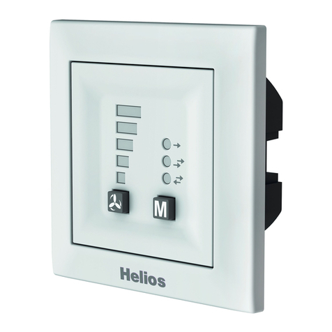
Helios
Helios KWL 45 BEU User manual
Helios
Helios TSD 0,8 User manual
Helios
Helios ESA 5 User manual
Helios
Helios TSD 0,8-11 User manual
Helios
Helios EDR Owner's manual
Helios
Helios KWL-BE User manual
Helios
Helios 5 Target User manual
Helios
Helios ESA User manual
Helios
Helios PA Series User manual
Helios
Helios 90 770 User manual
