manuals.online logo
Brands
  1. Home
  2. •
  3. Brands
  4. •
  5. Helios
  6. •
  7. Controllers
  8. •
  9. Helios TDS 0,8 User manual

Helios TDS 0,8 User manual

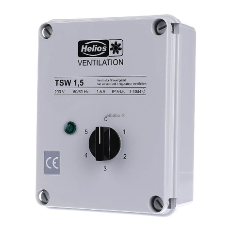
Transformátorový regulátor otáček TSD 0,8 – 11 / TSW 1,5 – 12
Transformer controller TSD 0,8 – 11 / TSW 1,5 – 12
Régulateur de vitesse à transformateur TSD 0,8 – 11 / TSW 1,5 – 12
1
MONTÁŽNÍ A PROVOZNÍ PŘEDPIS Č. 90 772
Pro zajištění bezchybné funkce a vlastní
bezpečnosti je nutné důkladně pročíst a
respektovat všechny následující předpisy!
PŘEVZETÍ
Zásilku ihned po doručení prověřit z hlediska škod a
správnosti typu přístroje. V případě, že se vyskytly
škody, musí být neprodleně nahlášeny přepravní
společnosti. V případě, že reklamace nebude
uplatněna včas, ztrácí zákazník jakékoliv eventuální
nároky.
USKLADNĚNÍ
Místo uskladnění musí být chráněno před otřesy,
vodou a teplotními výkyvy. Škody vzniklé vlivem
nevhodné přepravy, nevhodného uskladnění nebo
uvedení do provozu jsou prokazatelné, a tudíž
nepodléhají nároku na záruku.
OBLAST POUŽITÍ
Tyto 1 a 3 transformátorové regulátory otáček jsou
jednotky k 5ti-stupňovému řízení otáček vhodných
ventilátorů. Na jeden řídící přístroj může být
připojeno více ventilátorů (i s motory odlišných
výkonů) až po zatížení jmenovitého proudu řídícího
transformátorového řídícího přístroje.
Vývodem NK-LK může být např. ovládána jedna
klapka. Na LK je 230 V, pokud se stupňový spínač
nenachází na pozici „0“.
DŮLEŽITÉ: Motor, resp. motory, které jsou
připojeny na řídící transformátor, musí být vhodné
pro provoz se změnou počtu otáček prostřednictvím
transformátoru (řízení napětí). Max. odběr proudu
motoru (motorů) nesmí překročit max. výchozí
proud řídícího transformátoru. Motor není
monitorován. Toto musí být zajištěno pomocí
vhodného příslušenství přímo při instalaci (např.
MW a MD).
-max. proud
Při výběru regulátoru je třeba dbát na rozdílný odběr
proudu při rozdílných napětích. Toto je při přiřazení
regulátorů k jednotlivým ventilátorům v tištěných
materiálech již zohledněno. V případě, že jsou
regulátory k existujícím zařízením vybírány
samostatně, je třeba dbát na max. přípustný proud
podle diagramu (viz. níže), v opačném případě se
může regulátor přehřát.
OBECNÁ UPOZORNĚNÍ
Podle VDE 100 část 720 a 705 je nutné zajistit
elektrické stroje pomocí vhodných zařízení pro
ochranu motoru.
Průzkumy a statistická vyhodnocení výpadků motorů
ukázaly, že byl ve většině případů motor zničen příliš
vysokými teplotami. Především u pohonů ventilátorů
nebývá příliš vysoká teplota vinutí pouze důsledkem
blokovaného rotoru, nýbrž také výsledkem:
-silného znečištění
-příliš nízkého průtoku vzduchu při zavřené klapce
-příliš vysokého přepravního média
-špatného zacházení
-špatného směru otáčení (radiální ventilátory)
-příliš nízkého protitlaku (radiální ventilátory)
-provozu v nepřípustné oblasti charakteristické
křivky
-příliš častého zapínání/vypínání
-ložisek s těžkým chodem
Pro zamezení totálního výpadku zařízení
doporučujeme zajistit kontrolu motoru teplotním
sledováním pomocí termokontaktů a odpovídajícím
spouštěcím přístrojem s blokováním opětovného
spuštění.
INSTA ATION AND OPERATING INSTRUCTIONS
NO 90 772
It is important for safety reasons, that you read
and observe these instructions fully before pro-
ceeding.
RECEIPT
Please check consignment immediately on receipt for
accuracy and damage. f damaged, please notify car-
rier immediately. Delay in notification may invalidate
any possible claim.
STORAGE
The storage area must be free of water, vibration and
temperature variations.
Damages due to improper storage, transportation or
installation are not liable for warranty.
OPERATION
These single phase and three phase controllers regu-
late the speed of the motor in 5 steps . Several venti-
lators (also with motors of different ratings) may be
connected to one controller. However, the total load
current must not exceed the nominal output current
of the controller.
The NK-LK give a full single phase power output to
switch other equipment on at the same time as the
motor. (e.g. Motorised shutter).
IMPORTANT: The motor(s)for connection to the con-
troller must be suitable for transformer reduced volta-
ge speed control. The total maximum current load of
(all)the motor(s)connected to the controller must not
exceed the nominal output current of the transformer
speed controller. A motor protection is not included
in this unit. Suitable motor protection must be provi-
ded with in the system. (for example MW and MD).
- Max. current
For the selection of a controller the different power
consumption in connection with the voltage has to
be put into consideration. n the publication of Helios
the allocation of the different controllers has to be in-
dicated. f the controllers will be selected by the cli-
ents the max. admissible current has to be conside-
red according to the diagram (see below) because
the controller could be overheated.
GENERA INFORMATION
According to the regional and national electrical sa-
fety regulations as well as the EN-Norm, all electrical
motors are to be protected through a suitable motor
protective device. Most motors are destroyed
through overheating. Causes can include:
- impeller obstruction
- excessive dust or dirt on motor
- too low air flow, where shutters are used
- too high air flow temperature
- incorrect operation
- wrong direction of rotation (centrifugal fans)
- resistance too low (forward curved centrifugal fans)
- operation at unsuitable working point (see perfor-
mance curve)
- frequent switching
- worn bearings
To avoid damaging the equipment, Helios recom-
mend monitoring the motor temperature through
thermal contacts connected to a manually resettable
motor protection device.
MOUNTING
The maximum admissible ambient temperature du-
ring operation is + 40°C. The controller must be mo-
unted vertically onto a solid surface, or horizontal to a
solid, not inflammable surface. The controller must
not be mounted upside down. The cable entries
should point down.
NOTICE DE MONTAGE ET D’UTI ISATION
NR. 90 772
Il est important de lire et de respecter l'ensemble
des prescriptions suivantes, pour le bon fonc-
tionnement de l'appareil et la sécurité des utilisa-
teurs.
RECEPTION
Dès réception, vérifier l'état et la conformité du
matériel commandé. En cas d'avaries, des réserves
doivent être portées sur le bordereau du transporteur.
Elles doivent être précises, significatives, complètes
et confirmées dans les 3 jours par lettre recommandée.
Attention: le non-respect du délai peut entraîner le re-
jet de la réclamation.
STOCKAGE
Le matériel est à stocker dans un endroit abrité de
l'eau, exempt de variations de température et de vi-
brations. Les dommages dus à de mauvaises condi-
tions de transport, à des stockages défectueux ou à
une utilisation anormale sont sujets à vérification et
contrôle et entraînent la suppression de notre garantie.
DOMAINE D’UTI ISATION
Ces régulateurs de vitesse à 5 étages à transforma-
teur 1~ et 3~ sont conçus pour des moteurs régula-
bles. Plusieurs ventilateurs (même de puissances et
de types différents) peuvent être raccordés à un
même transformateur.
Les bornes NK-LK permettent par ex. de comman-
der un volet. La tension à la borne LK est de 230 V, si
le sélecteur n’est pas en position „0“.
IMPORTANT: Le(s) moteur(s) doit (doivent) être
conçus pour la régulation de vitesse par modifica-
tionde tension. Le courant nominal du moteur ne doit
pas excéder celui indiqué sur la plaque signalétique
du transformateur. l n’y a pas de protection moteur.
La prévoir en utilisant des accessoires adaptés (par
ex. MW et MD).
– Courant maximum
Pour la sélection des TSD/TSW, il faut tenir compte
des courants admissibles aux différentes tensions. Les
régulateurs affectés aux ventilateurs Helios ont été dé-
terminés en tenant compte de cette caractéristique. Si
les régulateurs sont utilisés avec d’autres ventilateurs
ou installations, vérifier le courant admissible en réduc-
tion de tension (risque de surchauffe du transforma-
teur). Voir diagramme ci-dessous.
REMARQUES GENERA ES
Selon les normes de sécurité électriques régionales
et nationales VDE 100 partie 720 et partie 705 et se-
lon les normes EN, les moteurs électriques doivent
être protégés par un appareil de protection approprié.
Les recherches et études statistiques sur des mo-
teurs cassés ont montré que dans la plupart des cas,
le moteur a été détruit à cause des températures
trop élevées. Surtout sur les ventilateurs, une
température trop élevée du bobinage ne résulte pas
seulement d’un blocage de l’hélice mais aussi:
– d’un encrassement
– d’un débit d’air insuffisant, par ex. volets fermés
– d’une température du fluide véhiculé trop élevée
– d’un mauvais mode d’application
– d’un mauvais sens de rotation
(ventilateurs centrifuges)
– d’une perte de charges trop faible (ventilateurs
centrifuges)
– d’un fonctionnement dans une plage de la
courbe du ventilateur non admise
– d’un fonctionnement marche-arrêt trop fréquent–
– d’une surcharge par roulements à billes grippés.
Transformátorový regulátor otáček TSD 0,8 – 11 / TSW 1,5 – 12
Transformer controller TSD 0,8 – 11 / TSW 1,5 – 12
Régulateur de vitesse à transformateur TSD 0,8 – 11 / TSW 1,5 – 12
2
INSTALACE
Max. okolní teplota během provozu je +40°C. Řídící
přístroj musí být namontován kolmo na stabilní
stěnu nebo horizontálně na stabilní, nehořlavou
podložku. Řídící přístroj nesmí být montován vzhůru
nohama (tzn. vrchem dolů). Tzn., že přípojky kabelů
musí směřovat dolů. Nesmí být montován přímo na
strop nebo přímo pod něj. Aby byl přístroj
dostatečně ochlazován, musí být kolem něj dodržen
odstup minimálně 5 cm, aby byla umožněna
dostatečná cirkulace vzduchu.
BEZPEČNOST
Při vestavbě je nutné dbát na předpisy BOZP (VDE,
DIN).
ELEKTRICKÁ INSTALACE
POZOR: Všechny práce je nutné provádět ve stavu
bez napětí.
Elektrické připojení smí být provedeno pouze
autorizovaným elektrikářem. Je třeba dodržovat
příslušné bezpečnostní předpisy, normy a směrnice
(VDE 0100 a VDE 0700, stejně jako TAB’s a EVU’s a
UW). Mimoto je nutné dbát na provozní a montážní
předpisy ventilátorů.
Zavedení přívodního vedení je třeba provést tak, aby
se dovnitř podél vedení nemohla dostat voda. Vedení
nikdy nesmí vést přes ostré hrany.
PROVOZ VE SPOJENÍ S KANÁLOVÝM
VENTILÁTOREM KVD.. EX A STROPNÍM
VENTILÁTOREM RD…EX
Je-li to v souladu s Ex-prohlášením o shodě motorů
ventilátoru, může být počet otáček tohoto typu
přístroje ovládán pomocí TSD. Je přitom třeba dbát
na následující:
-TSD musí být nutně instalován mimo Ex-oblast.
-Jelikož není povolen provoz při 80 V, musí být
stupeň 1 změněn z 80 V na 115 V.
POZOR: Přívodní vedení motorů musí být
zajištěna na základě platných norem a směrnic.
Údaje z prohlášení o shodě motorů ventilátoru
jsou závazné!
MONTÁŽNÍ POSTUP
POZOR: Všechny práce musí být prováděny ve
stavu bez napětí.
a) mechanicky
-Sundat víko řídícího přístroje, resp. otevřít přední
dvířka.
-Na zadní straně se nacházejí montážní otvory. U
některých krytů z umělé hmoty je nutné tyto otvory
napřed propíchnout. U kovových krytů nejprve
odstranit zátku z umělé hmoty.
-Je-li to nutné, může být vyjmuta montážní deska se
všemi konstrukcemi, aby byla montáž ulehčena.
-Při montáži je nutné používat odolné šrouby, resp.
upevňovací materiály.
-Poté, co je namontován kryt, musí být uzavřeny
otvory (aby byla dodržena IP třída krytí).
b) elektricky
Řídící transformátor připojit podle přiloženého
schématu zapojení a nákresu svorkovnice. Ochranný
vodič (zeleno-žlutý) síťového napojení a každý další
přístroj, který je na transformátorový regulátor
otáček připojen, musí být připojen na svorky PE,
resp. svorkový bod PE (jsou-li k dispozici).
t must not be mounted directly under, or onto the
ceiling. To ensure adequate cooling, a minimum di-
stance of 5 cm is required around the controller.
SAFETY
Please ensure that the relevant safety regulations are
observed during installation and operation.
E ECTRICA CONNECTION
ATTENTION: All work must be carried out with the
equipment fully isolated from the power supply.
All electrical connections are to be carried out in ac-
cordance with the relevant wiring diagram and are
only to be carried out by a qualified electrician. All re-
levant safety regulations, national standards and
norms are to be adhered to. The nstallation and
Operation nstruction for the fans are also to be ob-
served.
The cable entry into the unit should be made using
the cable glands supplied to maintain the P rating of
the unit (i.e. to prevent moisture entering the unit).
Never pass electrical cable over sharp edges.
OPERATION IN CONNECTION WITH EXP O-
SION PROOF RECTANGU AR-CENTRIFUGA
FANS KVD..EX
f the fan motor is certified as being explosion proof
and speed controllable, this device can be speed
controlled by TSD. t is essential that the following are
observed:
- The TSD can not be used in the hazardous area
and must be installed outside of the Ex-range.
- Since an operation under 100 V is not permitted,
step 1 of the controller must be changed from
80 V to 100 V.
ATTENTION: The motor supply cables must be
secured according to the current standards an-
degulations. The specifications of the declaration
of conformity of the fan motors are obligatory.
INSTA ATION
ATTENTION: All work must be carried out with the
equipment fully isolated from the power supply.
a) mechanical
- Remove cover or open the door of the controller.
- Mounting holes are provided on the inside back pa-
nel of the enclosure.
- On some of the plastic enclosures the mounting ho-
les should be opened by knocking out the
membrane covering the mounting hole. Metal en-
closures have blanking plugs covering the moun-
ting holes.
- For the ease of mounting, the mounting plate may
be removed from the enclosure.
- The controller enclosure should be mounted using
corrosion resistant screws or bolts as required.
- Once secured in position, the mounting screws or
bolts should be sealed to maintain the P-rating
of the enclosure.
b) electrical
The controller should be wired in accordance with the
wiring diagram supplied with the controller and mar-
kings on the terminals. The earth-wire (green-yellow)
of the electrical supply and of any equipment con-
nected to the controller must be connected to the
terminals marked PE.
TERMINA NK / K
A shutter or another control unit for 230 V and max.
2 A can be connected to the terminal NK / LK.
PUTTING INTO OPERATION
Check if the switch of the controller is in "0" position.
Check the mains supply voltage (rated voltage, tole-
rance +6%, -10%).
Pour éviter la détérioration totale de l’installation, un
contrôle de la température dans le moteur par des
thermocontacts et un appareil de coupure et de pro-
tection totale du moteur avec réarmement manuel
après disjonction, sont conseillés.
INSTA ATION
La température ambiante pendant le fonctionnement
ne doit pas excéder +40°C. Le régulateur doit être
monté sur une paroi verticale ou sur un plan horizon-
tal stable non inflammable. Le régulateur ne doit pas
être monté à l’envers. Les entrées de connections
doivent en effet se trouver sous le régulateur.
L’appareil ne doit pas être monté directement sous
ou au plafond. Pour des raisons de refroidissement,
un espace de 5 cm autour du régulateur est à res-
pecter.
SECURITE
Lors de l’installation, il faut respecter strictement les
prescriptions concernant la protection du travail et la
prévention des accidents (VDE, D N).
BRANCHEMENT E ECTRIQUE
ATTENTION: Tous les travaux doivent être effec-
tués hors tension.
Le branchement électrique doit être effectué par un
électricien qualifié. Les consignes de sécurité et les
règles d'installation en vigueur ( VDE 0100, VDE 0700
et TAB, EVU, UVV) doivent être respectées. De plus,
il est impératif de respecter les indications données
dans la notice de montage et d’utilisation. Le passa-
ge du câble d’alimentation doit être effectué de telle
sorte qu’un éventuel filet d’eau ne puisse pas s’infilt-
rer le long du câble. Ne pas fairepasser le câble sur
des surfaces tranchantes.
FONCTIONNEMENT AVEC UN VENTI ATEUR
DE GAINE RECTANGU AIRE KVD... EX ET
RD... EX
Si le moteur du ventilateur a obtenu le certificat de
conformité Ex, ce type d’appareil peut être régulé
avec le régulateur TSD. Pour cela, prendre en compte
les éléments suivants:
– Le TSD doit être obligatoirement installé en dehors
de la zone antidéflagrante.
– Un fonctionnement en 80 V n’est pas permis,
il faut donc passer en vitesse 1 de 80 V à 115 V.
ATTENTION: le câblage du moteur doit se faire
conformément aux normes et directives en vi-
gueur. es indications données dans le certificat
de conformité Ex sont à respecter impérativement.
ETAPES DU MONTAGE
ATTENTION: tous les travaux doivent être effec-
tués hors tension.
a) Mécanique
– Enlever le couvercle ou ouvrir la porte du boîtier du
transformateur.
– A l’arrière des boîtiers se trouvent les points de
fixation. Pour certains boîtiers en plastique, ces
trous de fixation doivent être perforés. Pour les
boîtiers métalliques, il faut enlever les protections
en plastique des points de fixation.
– La plaque de base peut être enlevée pour faciliter
le raccordement.
– Pour la fixation, utiliser des vis et chevilles pour
fixation murale ou vis et écrous.
– Après la fixation, veillez à l’étanchéité des points
de fixation (pour maintenir la classe P).
b) Electrique
Raccorder le transformateur suivant le schéma de
raccordement livré avec le transformateur et les spé-
cifications indiquées sur les bornes de raccordement.
Le fil de terre (jaune-vert) de l’alimentation électrique
doit être raccordé à la borne PE, et éventuellement à
d’autres bornes PE si elles existent.
PŘIPOJENÍ NK/LK
Na svorku NK/LK může být připojena klapka nebo
jiný řídící přístroj s maximálně 230 V a max. 2 A.
UVEDENÍ DO PROVOZU
Prověřit, zda se spínač na řídícím transformátoru
nachází v pozici „0“. Prověřit síťové napětí
(jmenovité napětí, tolerance +6%, -10%). Nejprve
zapnout síťové napětí (síť) a poté řídící přístroj.
Zelené světlo vně přístroje musí svítit. Prověřit napětí
na každé spínací pozici (viz. technická data). V
případě problému prověřit pojistku v přístroji (pouze
TSW).
ÚDRŽBA
Řídící transformátor nevyžaduje žádnou zvláštní
údržbu. K čištění je možné použít vlhký hadr. V
žádném případě nesmí být čištěn stříkající vodou z
hadice.
POZOR: Všechny práce musí být prováděny ve
stavu bez napětí.
PŘÍSLUŠENSTVÍ, SPÍNACÍ A ŘÍDÍCÍ PRVKY
Použití příslušenství, které není doporučeno nebo
nabízeno firmou HELIOS, je nepřípustné a vede v
případě eventuální závady ke ztrátě nároku na
reklamaci.
NÁROKY NA ZÁRUKU – PROHLÁŠENÍ O
VYLOUČENÍ ODPOVĚDNOSTI
Nebudou-li dodržena uvedená doporučení, zaniká
nárok na záruku a opravu ze strany firmy. Totéž platí
pro žádosti o záruku od výrobce.
PŘEDPISY – SMĚRNICE
Při řádné instalaci a provozu na základě předpisů
odpovídá přístroj ke dni jeho výroby platným
předpisům a CE směrnicím.
Transformátorový regulátor otáček TSD 0,8 – 11 / TSW 1,5 – 12
Transformer controller TSD 0,8 – 11 / TSW 1,5 – 12
Régulateur de vitesse à transformateur TSD 0,8 – 11 / TSW 1,5 – 12
3
Switch on the mains power supply first, and then the
controller. The green light on the outside of the enclo-
sure will be on. Check the voltage given in every
switch position (see technical data). n case of failure,
check the fuse inside of the enclosure. (only TSW).
MAINTENANCE
The controller needs no specific maintenance. The
housing may be cleaned using a moist cloth. t must
not be hosed down.
ATTENTION: All work must be carried out with the
equipment fully isolated from the power supply.
ACCESSORIES, SWITCHES AND
CONTRO ING DEVICES
The use of accessories not offered or recommended
by Helios is not permitted. Any potential damage
claims become invalid.
WARRANTY - EXC USION OF IABI ITY
f the preceding instructions are not observed all war-
ranty claims are excluded. The Helios warranty is li-
mited to the material and workmanship of the pro-
duct.
CERTIFICATES
The products are manufactured in compliance with
applicable European standards and regulations.
0
20
40
60
80
100
120
230170130100 80
zatížitelnost (%)
TSW 3+ MWS 3
TSW 5+ MWS 5
TSW 7,5
TSW1,5+ TSW10+
TSW12+ MWS1,5+
MWS7,5+ MWS10
0
20
40
60
80
100
120
400 280200 14080
zatížitelnost (%)
RDS 1
RDS 2
RDS 4
RDS 7 + TSD 7
RDS 11 + TSD 11
TSD 0,8
TSD 1,5
TSD 3
TSD 5,5
křivka redukce proudu TSW 1,5-12
power reduction curves TSW 1,5 - 12
Courbes de réduction de courant TSW 1,5 - 12
Charge admissible en %
capacity (%)
křivka redukce proudu TSW 0,8 - 11
power reduction curves TSW 0,8 - 11
Courbes de réduction de courant TSW 0,8 - 11
capacity (%) Charge admissible en %
RACCORDEMENT NK / K
Une électrovalve ou un servo-moteur peuvent être
raccordés aux bornes LK et NK ( tension 230 V, maxi
2 A).
MISE EN MARCHE
Vérifier si le commutateur est en position "0”. Vérifier
la tension d’alimentation
(tension nominale, tolérance
+6%, –10%)
. Enclencher d’abord l’interrupteur
général et ensuite le régulateur. La lampe verte sur le
boîtier de commande doit alors s’allumer. Vérifier la ten-
sion pour chaque position du commutateur (confor-
mément aux données techniques). En cas de défaut,
vérifier le fusible à l’intérieur du boîtier
(seulement
TSW)
.
ENTRETIEN
Le régulateur à transformateur ne nécessite aucun
entretien particulier. Pour nettoyer le boîtier, utiliser un
chiffon humide. En aucun cas le régulateur ne doit
être nettoyé au jet d’eau.
ATTENTION: tous les travaux doivent être effec-
tués hors tension.
ACCESSOIRES, APPAREI S DE TEMPORISA-
TION ET DE REGU ATION
L’utilisation d’accessoires et d’équipements qui ne
sont pas directement fournis ou conseillés par Helios
n´est pas autorisée. Nous déclinons toute respons-
abilité en cas de défaut consécutif à leur utilisation.
DEMANDE DE GARANTIE - RESERVES DU
CONSTRUCTEUR
En cas de non-respect des indications précédentes,
toute demande de remplacement ou de réparation à ti-
tre gratuit sera déclinée. l en sera de même pour tou-
te implication de responsabilité du fabricant
REG EMENTATIONS - NORMES
Cet appareil est conforme aux directives CE en vi-
gueur le jour de sa fabrication sous réserve d’une uti-
lisation appropriée.
Transformátorový regulátor otáček TSD 0,8 – 11 / TSW 1,5 – 12
Transformer controller TSD 0,8 – 11 / TSW 1,5 – 12
Régulateur de vitesse à transformateur TSD 0,8 – 11 / TSW 1,5 – 12
vývod pro klapku
Port for shutter
Sortie pour volet
92822 001 SS-437,1 07.06.10
TSW 5,0 bis 12
max A
PE PE N L1
NU1NKLK
MW
TK M
1~ TK M
1~
MW
L1NPE
230V 50/60 Hz
PE
2 2
TSD 0,8 - 11,0
F=Imax
92823 002 SS-436,2 20.01.04
PE L1 L2 L3N
MD
MD
M
3~
M
3~
TK TK
PE PE PE N N L1 L2 L3 U1 V1 W1NK LK 80V 115V 80V 115V
vývod pro klapku
Port for shutter
Sortie pour volet
FHEL OS Ventilateurs · Le Carré des Aviateurs · 157 av. Charles Floquet · 93155 Le Blanc Mesnil Cedex
GB HEL OS Ventilation Systems Ltd. · 5 Crown Gate · Wyncolls Road · Severalls ndustrial Park ·
Service und Information
CZ Ventila vzduchotechnika s.r.o. Světova 1041/9, Praha 8, 180 00
D HEL OS Ventilatoren GmbH & Co · Lupfenstraße 8 · 78056 VS-Schwenningen
CH HEL OS Ventilatoren AG · Steinackerstraße 36 · 8902 Urdorf / Zürich
A HEL OS Ventilatoren GmbH · Postfach 854 · Siemensstraße 15 · 6023 nnsbruck
Colchester · Essex · CO4 9HZ
Druckschrift-Nr. 90 772 / 06.10
vývod pro klapku
Port for shutter
Sortie pour volet
85155 001 SS-960 07.06.10
TSW 1,5 bis 3,0
max A
PE PE NNL1 U1NKLK
MW
TK M
1~ TK M
1~
MW
L1NPE
230V 50/60 Hz
PE
2 2
SS-436.2
SS-960
SS-437.1

This manual suits for next models

23

Other Helios Controllers manuals

Helios 90 770 User manual

Helios

Helios 90 770 User manual

Helios ESE 2,5 Service manual

Helios

Helios ESE 2,5 Service manual

Helios KWL-MZB-BE User manual

Helios

Helios KWL-MZB-BE User manual

Helios 5 Target User manual

Helios

Helios 5 Target User manual

Helios KWL-BEC User manual

Helios

Helios KWL-BEC User manual

Helios ESA 5 User manual

Helios

Helios ESA 5 User manual

Helios AIR1-BE TOUCH User manual

Helios

Helios AIR1-BE TOUCH User manual

Helios TSD 0,8-11 User manual

Helios

Helios TSD 0,8-11 User manual

Helios AIR1-BE ECO User manual

Helios

Helios AIR1-BE ECO User manual

Helios PA Series User manual

Helios

Helios PA Series User manual

Helios MWS User manual

Helios

Helios MWS User manual

Helios WS 1,5 User manual

Helios

Helios WS 1,5 User manual

Helios ESA User manual

Helios

Helios ESA User manual

Helios KWL 45 BEU User manual

Helios

Helios KWL 45 BEU User manual

Helios EDR Owner's manual

Helios

Helios EDR Owner's manual

Helios KWL-BE User manual

Helios

Helios KWL-BE User manual

Helios TSD 0,8 User manual

Helios

Helios TSD 0,8 User manual

Helios KWL-MZB-ZR User manual

Helios

Helios KWL-MZB-ZR User manual

Helios KWL-BE Touch User manual

Helios

Helios KWL-BE Touch User manual

Helios ETR User manual

Helios

Helios ETR User manual

Helios ESA User manual

Helios

Helios ESA User manual

Helios KWL-BE Eco User manual

Helios

Helios KWL-BE Eco User manual

Helios EDR Owner's manual

Helios

Helios EDR Owner's manual

Helios ESD User manual

Helios

Helios ESD User manual

Popular Controllers manuals by other brands

Haier YR-E17A Operation & installation manual

Haier

Haier YR-E17A Operation & installation manual

Daikin SLM operating manual

Daikin

Daikin SLM operating manual

Panasonic FP2 Series Technical manual

Panasonic

Panasonic FP2 Series Technical manual

USA Technologies VendingMiser VM170 installation instructions

USA Technologies

USA Technologies VendingMiser VM170 installation instructions

KaMo MDF Series manual

KaMo

KaMo MDF Series manual

Comunello Automation SHOWIN S45 3FC instruction manual

Comunello Automation

Comunello Automation SHOWIN S45 3FC instruction manual

Linak TECHLINE LA25 quick start guide

Linak

Linak TECHLINE LA25 quick start guide

YASKAWA GA700 Technical manual

YASKAWA

YASKAWA GA700 Technical manual

MWM PHASE ESSENTIAL quick start guide

MWM

MWM PHASE ESSENTIAL quick start guide

Koganei MSU-PH-EA Series owner's manual

Koganei

Koganei MSU-PH-EA Series owner's manual

Digilent DMC60C Reference manual

Digilent

Digilent DMC60C Reference manual

WT sensor PCPH02 quick start guide

WT sensor

WT sensor PCPH02 quick start guide

THORLABS BBD201 user guide

THORLABS

THORLABS BBD201 user guide

AMERITRON SDC-105 instruction manual

AMERITRON

AMERITRON SDC-105 instruction manual

KUSSMAUL 091-86-1901 manual

KUSSMAUL

KUSSMAUL 091-86-1901 manual

Kilews SKP-32B-60W Operation and maintenance manual

Kilews

Kilews SKP-32B-60W Operation and maintenance manual

Hach sc1000 user manual

Hach

Hach sc1000 user manual

Redarc SBI12-LLD Install manual

Redarc

Redarc SBI12-LLD Install manual

manuals.online logo
manuals.online logoBrands
  • About & Mission
  • Contact us
  • Privacy Policy
  • Terms and Conditions

Copyright 2025 Manuals.Online. All Rights Reserved.