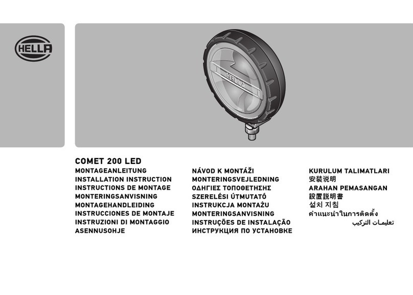
Hella RokLUME 280N SMART User manual

94 avenue Gambe tta - 75020 PARIS
+33 (0)1 85 56 97 00 www.carrenoir.com
Ce fichier e st un docume nt
d’exécuti on créé sur Il lustr ator
version C S6.
0 1 2
ÉCHELLE 1/1
TONS RECOMMANDÉS (RVB)
FAURECIA
FAU_22_00002_ForviaHella_Logo_RVB
JFB
Date : 26/01/20 22
TECHNIQUE
R0 V36 B211
#0024d3
RokLUME 280N SMART
User Manual

2
Table of Contents
1. Terms and abbreviations
2. SMART Lighting System BASE
3. SMART Lighting System PRIME
3.1 SMART work lamps
3.2 Gateway
3.3 Control Panel
3.4 Standard work lamps used as cornering light
3.5 PLC bus
3.6 CAN Bus
4. System activation
4.1 Teaching
5. Normal operation mode
5.1 Control Panel usage
5.2 Control Panel normal operation mode
5.3 Keylock on the Control Panel
6. Control Panel Hidden Menu mode
6.1 Enter and leave Hidden Menu
6.2 Queries and control at Hidden Menu
7. Summaries
7.1 Control Panel legend
8. Safe operation mode
9. Maintenance
9.1 Adding a new SMART work lamp
9.2 Removing SMART work lamps
9.4 Replacing a Gateway
9.5 Replacing a Control Panel
10 Error handling
3
4
4
5
6
7
7
7
7
8
8
8
8
10
11
11
11
11
12
15
15
15
15
16
16
16
16
16
16
17

3
3
1. Terms and abbreviations
ACL Automatic Cornering Light. The SMART Lighting Gateway PRIME is
capable to additionally connect two standard work lamps as cornering
ATM Anti-Theft Mode.
can be mounted on other vehicles having HELLA’s SMART Lighting
System.
CAN Controller Area Network. A serial communication bus and protocol
between Control Panel and Gateway. SMART Lighting devices use the
SAE J1939 standard.
CP Control Panel.
GWB SMART Lighting Gateway BASE
lamps only.
GWP SMART Lighting Gateway PRIME
GW Gateway.
HM Hidden Menu at the Control Panel. This menu can be reached by
entering a button combination
LTW Lifetime Warning
measured light output in combination with the operating hours and
and to the Control Panel.
PLC Power Line Communication. PLC allows data communication and
electric power transmission utilizing the same electrical line.
UID Unique Identication Data.
WL Work lamp.

4
2. SMART Lighting System BASE
3. SMART Lighting System PRIME
Example SMART Lighting BASE component diagram connection
Example SMART Lighting PRIME component diagram connection
RokLUME 280N SMART work lamps (995.707-XXX) Control Panel (333.525-001)
Cornering Light 995.706-501 (RokLUME 280N Gen. 2)
or 996.476-701 (RokLUME C180)
↔CP (333.557-001)
Components:

5
Both SMART Lighting Systems BASE and PRIME use PLC (Power Line Communication) on the
and the SMART work lamps.
The Control Panel will be powered by the Gateway.
Gateway and Control Panel devices use the SAE J1939
communication.
3.1 SMART work lamps
1GA 995 707-401
1GA 995 707-411
1GA 995 707-421 ZERO
1GA 995 707-431
1GA 995 707-441
1GA 995 707-451
1GA 995 707-461
1GA 995 707-471
1GA 995 707-481 ZERO
1GA 995 707-491
1GA 995 707-501
1GA 995 707-511
1GA 995 707-551
1GA 995 707-561
1GA 995 707-571 ZERO
1GA 995 707-581
1GA 995 707-591
1GA 995 707-601
1GA 995 707-8XX RL280 SMART Kits
RokLUME 280N SMART work lamps (995.707-XXX) Control Panel (333.525-001)
Cornering Light 995.706-501 (RokLUME 280N Gen.2)
or 996.476-701 (RokLUME C180)
↔CP (333.557-001)
Gateway PRIME (333.523-001) ↔Cornering Light (994.246-071)
Components:

6
3.2 Gateway
a SMART Lighting System.
Gateway connectors:
C1/C5 not used
C2
C3 6-pin Deutsch DT connector - SAE J1939 (CAN Bus) and PLC connection
C4 2-pin Deutsch DT connector - standard cornering lamp right
The Gateway has two variants:
a) Gateway BASE
This Gateway variant uses the 6-pin connector C3 to connect the Control Panel through
CAN Bus and the SMART work lamps through the PLC bus. Gateway BASE can control
SMART work lamps only.
b) Gateway PRIME
This Gateway variant uses the 6-pin connector C3 to connect the Control Panel through
PRIME uses two 2-pin connectors C2 and C4
Attention:
SMART work lamps should not be connected to C2 and C4
Gateway connector assignment
Gateway Connectors for
CAN+PLC ACL right
BASE C3 not used not used
PRIME C3 C2 C4

7
3.3 Control Panel
separately
indicators.
3.4 Standard work lamps used as cornering light
lights on the vehicle in the PRIME system. The standard cornering lamps are powered
or RokLUME C180 996.476-701.
3.5 PLC bus
communication between Gateway and the connected SMART work lamps. These devices
3.6 CAN Bus
The CAN Bus is a wired device connection between Gateway and Control Panel. The
devices communicate by sending and receiving messages according to the CAN Bus SAE
J1939 protocol.

8
5. Normal operation mode
Normal operation means that all the SMART work lamps are running and are under
previous settings or adjusting the operating commands with the Control Panel.
5.1 Control Panel usage
Lighting System.
Gateway BASE or PRIME.
4. System activation
a system initialization should be executed.
4.1 Teaching
Through the teaching the SMART Lighting Gateway BASE or PRIME and the SMART
Chapter 6.2.3.
iA Smart Lighting System consists of one Gateway and at least one
Smart work lamp. All Smart Lighting devices will be delivered with
preprogramed UID and device type in the Electronic Control Unit.

9
1decrease brightness
2increase brightness
4decrease colour temperature
5increase colour temperature
6
Lighting Control Panel.
Control Panel buttons:
Control Panel indicators:
L1 – L6 brightness indicators (7 stages: 0-6 LEDs light up)
L7
no special function
L9 white colour mode indicator
L10 – L15 colour indicators (7 stages: 0-6 LEDs light up)
L16 – L18

10
Button operation Control Panel action Eects
Press 1 Decrease brightness.
brightness.There are 7 levels: no LED
Press 2 Increase brightness. Next brightness LED to the right will
brightness.There are 7 levels: no LED
Press 3
is set.
Press 4 Decrease colour temperature level. LEDs L10 – L15 indicate the colour
temperature level.There are 7 levels:
Press 5 Increase colour temperature level. LEDs L10 – L15 indicate the colour
temperature level. There are 7 levels:
Press 6 Store a light setting:
Press button 6 up to three times to choose a
Make your light settings with the buttons 1 to 5.
P
store this light setting on the chosen memory
position.
Change a light setting:
To change the light setting on a memory
the setting
indicate the chosen memory position
three seconds.
Attention:
5.2 Control Panel normal operation mode
3 light and colour combinations.

11
5.3 Keylock on the Control Panel
but not to change these settings.
5.3.1 Activate Keylock
Action Press button sequence 5-1-3-2-4
Indication all LEDs on the CP are blinking 2x at 2Hz
Buttons 1-2-3-4-5 are locked
OR
Light settings were changed
5.3.2 De-activate Keylock
Action Press button sequence 5-1-3-2-4
Indication all LEDs on the CP are blinking 2x at 2Hz
Buttons 1-2-3-4-5 can be used again
OR
Control Panel is still locked (button combination was
5.4 Notication of Lifetime Warning on the Control Panel
all LEDs on the Control Panel are blinking 5x at 1Hz
work lamps continue working with the last light settings
Menu.
6. Control Panel Hidden Menu mode
can be changed.
6.1 Enter and leave Hidden Menu
6.1.1 Enter Hidden Menu
Action Press button sequence 1-5-4-3-2
Indication all LEDs on the CP are blinking 2x at 2Hz
logged on to Hidden Menu
OR
held too short)

12
6.1.2 Leave Hidden Menu
Action Hold button 6
Indication all LEDs on the CP are blinking 2x at 2Hz
logged out and last light settings restored
OR
Remaining logged on (button held too short)
6.2 Queries and control at Hidden Menu
Query lifetime status
Action Press button 1
Existing warning
Indication
LEDs L1-L2-L3
menu will be exited.
Aected work lamps -
til the submenu or the hidden menu will be exited.
Attention:
Exit submenu Press button 1
No existing warning
Indication LEDs L1-L2-L3
Exit submenu
The
against th
one.
activated theft mode is mounted on a machine without
any
de-activated theft mode is mounted on a machine
without any
menu.
LEDs L4-L5-L6 light up until leaving the Hidden Menu.
No LEDs L4-L5-L6 light up on the CP.

13
Activation (if feature was not active)
Action Press button 2
Indication LEDs L4-L5-L6 are blinking 3x at 1Hz then light up until
leaving the Hidden Menu.
Deactivation (if feature was activated)
Action Press button 2
Indication LEDs L4-L5-L6
Table below shows the necessary steps.
together at the machine. Using Gateway Prime the connected standard cornering lights
6.2.3 System teaching using Control Panel
Execution in Hidden Menu only.
Action Press button 4
Indication LEDs L10-L11-L12
LEDs L10-L11-L12
Attention:
Button operation Control Panel action Eects
Press buttons
1-5-4-3-2
All 18 indicators light up 2x at 2Hz Hidden menu mode entered.
Press 2
Indicators L4-L5-L6 light constantly.
actual status will be displayed.
Press 6 All 18 indicators light up 2x at 2Hz Exit hidden menu.

14
Table
Button operation Control Panel action Eects
Press buttons
1-5-4-3-2
All 18 indicators light up 2x at 2Hz Hidden menu mode entered.
Press 4
Indicators L10-L11-L12 light up as running light
This process needs approx. 6 seconds
Initialization done.
Press 6 All 18 indicators light up 2x at 2Hz Exit hidden menu.
Other buttons in Hidden Menu
The button 3and 5are not allocated.
Button 6 is to exit the hidden menu.

15
7. Summaries
7.1 Control Panel legend
all LEDs on CP blinking 2x at 2Hz →enter or leave Hidden Menu
→
seconds
5x blinking at 1Hz on all LEDs on CP →
3 LEDs at button 1 on the CP at 1Hz blinking permanently →
Hidden Menu
→
Hidden Menu available
3 LEDs at button 2 light up continuously →ATM activated
no LED at button 2 light up continuously →ATM deactivated
3 LEDs at button 2 on CP at 1Hz 3x blinking →
Running light at button 4 →Teaching in progress
→
7.2 Work lamp legend
5000K until deactivation by button 1 →
runs in the background
SMART work lamps are delivered in uninitialized state
8. Safe operation mode
connection to its Gateway BASE or PRIME.
Case #1: CAN Bus connection lost
Case #2: PLC connection lost
Case #3: CAN Bus and PLC connection lost

16
9. Maintenance
9.1 Adding a new SMART work lamp
A new SMART work lamp can be added to an existing HELLA SMART Lighting System. In
•
•mount the new SMART work lamp
•connect the new SMART work lamp to the on-board electrical system
• switch on the power
The running Gateway will begin to recognise the newly connected SMART work lamp
automatically.
9.2 Removing SMART work lamps
•
•
•dismount the SMART work lamp
•switch on the power
and will continue working.
9.3 Connect SMART work lamp from another vehicle
HELLA SMART work lamps in a HELLA SMART Lighting System are interchangeable
•
•mount the new SMART work lamp
•connect the new SMART work lamp to the on-board electrical system
•switch on the power
•
initialised and listed on the Gateway automatically.
9.4 Replacing a Gateway
Gateway BASE with a PRIME version and vice versa.
9.5 Replacing a Control Panel

17
10. Error handling
Table: Error handling at the SMART system
Error
No.
Device
Type
Situation Description Possible cause Troubleshooting
1 GW Assembly Device type not
known
Check label and connectors
connector)
2 GWP Cornering lights Cornering lights
do not work
Pin assignment OR
mounting position
is not correct
Check the pin assignment
AND the mounting position
according to the Installation
Manual.
Use only standard work lamps
not SMART work lamps
3 GWP Cornering lights Cornering lights
are in the wrong
turn
not correct
Check assemblage due to
Installation Manual
4 GW Already initialised
vehicle installed
in HM do not
work correctly
attached SMART
recognised
Run initialization using Hidden
Menu at CP
5 WL Already used
another vehicle
installed
in HM do not
work correctly
contains the old
attached SMART
yet
Run initialization using Hidden
Menu at CP
6 CP Memory button
does not react
1: Cut connection between CP
2: Replace the CP and restart
SMART Lighting System
7 CP No LED lights up
(e.g. Gap at in-
creased dimming)
Replace CP
8 CP Single LED does
not light up
(e.g. light gap
at increased
dimming)
Communication
error
1: Restart power supply (e.g.
2: Cut and reconnect cable
harness
9 CP Unregulated
dimming changes
changes
buttons
Replace CP
10 CP CP is not
input
CAN Bus cable to
Check the cable harness
11 CP
at start-up
(power on but CP
remains dark)
CP is not powered
Check the cable harness

18
Error
No.
Device
Type
Situation Description Possible cause Troubleshooting
12 WL Colour change
applicable)
CAN Bus command
not realised
1: Check CP status (indicators
should light up) →check the
power supply →replace CP
-
tors should light up due to
button control) →check pow-
er supply and cable connec-
3: Check the colour changes
devices can react to changes
as well)
13 CP No indicators
light up
constantly
Power supply or
CAN connection to
Check the cable harness to

94 avenue Gambetta - 75020 PARIS
+33 (0)1 85 56 97 00 www.carrenoir.com
Ce fichier est un document
d’exécution créé sur Illustrator
version CS6.
0 1 2
ÉCHELLE 1/1
TONS RECOMMANDÉS (1)
FAURECIA
FAU_22_00001_Forvia_SymboleF_Blanc
JFB
Date : 25/01/2022
TECHNIQUE
Blanc Logo
HELLA GmbH & Co. KGaA
Rixbecker Straße 75
Tel. + 49 2941 38 - 0
94 avenue Gambetta - 75020 PARIS
+33 (0)1 85 56 97 00 www.carrenoir.com
Ce fichier est un document
d’exécution créé sur Illus trator
version CS6.
0 1 2
ÉCHELLE 1/1
TONSRECOMMANDÉS
FAURECIA
FAU_22_00002_ForviaHella_Logo_Blanc
JFB
Date : 26/01/2022
TECHNIQUE
Blanc Logo
Other manuals for RokLUME 280N SMART
1
Table of contents
Other Hella Lighting Equipment manuals
Hella
Hella Luminator 4000 Compact LED User manual

Hella
Hella C140 LED User manual

Hella
Hella UltraBeam HMUBH19WBA User manual
Hella
Hella 2SE 357 032-021 User manual
Hella
Hella BST Series User manual

Hella
Hella M60 User manual
Hella
Hella LED LIGHT BAR 470 SINGLE TWIN User manual
Hella
Hella 2RL 008 061-001 User manual

Hella
Hella 2BM 008 355-001 User manual
Hella
Hella 005 020 Series User manual
