Hioki BT5525 User manual

BT5525
Instruction Manual
BATTERY INSULATION
TESTER
EN
Oct. 2022 Edition 1
BT5525A961-00 22-10H
Read carefully before use.
Keep for future reference.
When using the instrument for the
rst time Troubleshooting
Safety Information p.12 Troubleshooting p.195
Part Names and Functions p.18 Error p.197
Test Flow p.24
BT5525 BATTERY INSULATION TESTER
[600630710]
HIOKI BT5525A961-00

HIOKI BT5525A961-00

3
Setting the test voltage in the
Measurement screen ................................36
Setting the test voltage in the Setting
screen ......................................................37
3.3 Setting the Sampling Time ..................38
3.4 Setting the Measurement Delay
Time........................................................39
3.5 Setting the Test Time and
Comparator Delay Time.......................40
Setting the time during which a test
voltage is applied......................................40
Setting the comparator delay time .............41
3.6 Judging the Measured Value
(Comparator Function).........................44
3.7 Setting the Test Mode ..........................46
3.8 Notifying the Judgment Result and
Test Completion with a Beep ..............47
4 Test Method 49
4.1 Starting a Test .......................................49
4.2 Display during a Test............................51
4.3 Displaying the Measured Value..........52
4.4 Memory Function..................................53
4.5 Ending the Test .....................................55
4.6 Discharging Residual Electric
Charge (Auto Discharge Function) ....56
5 Various Functions 57
5.1 Checking for Any Contact Defects
and Conrming Contact Condition
(Contact Check Function) ...................58
5.2 Detecting Micro Insulation Failure
(BDD Function) .....................................60
Enabling the BDD function and setting
the threshold value ...................................61
Enabling the BDD stop function.................62
Enabling BDD judgment............................63
5.3 Limiting the Current to Be Applied
to the Device Under Test (DUT) .........64
Setting the current limit value manually......65
Setting the current limit value
automatically ............................................66
Contents
Introduction........................................................7
Checking Package Contents...........................8
Options...............................................................9
Symbols and Abbreviations...........................10
Safety Information ..........................................12
Precautions for Use........................................14
1 Overview 17
1.1 Product Overview .................................17
1.2 Features.................................................17
1.3 Part Names and Functions .................18
1.4 Screen Conguration and
Operation Overview .............................21
Measurement screen ................................21
Setting screen ..........................................22
1.5 Test Flow................................................24
2 Test Preparation 25
2.1 Inspecting the Instrument before
Test .........................................................26
Checking the insulation resistance test ......27
2.2 Supplying Power to the Instrument....28
Connecting the power cord .......................28
Turning the instrument on and o ..............29
2.3 Connecting the Test Leads..................30
2.4 Connecting a Communications
Cable......................................................30
2.5 Connecting the Test Leads to the
Device Under Test (DUT) ....................31
2.6 Shutting Down the Output of the
Instrument (Interlock Function)...........32
3 Basic Settings 33
3.1 Setting the Test Voltage.......................34
Setting the test voltage in the
Measurement screen ................................34
Setting the test voltage in the Setting
screen ......................................................35
3.2 Setting the Range (Auto/Manual).......36
Contents
BT5525A961-00
HIOKI BT5525A961-00

Contents
4
NPN setting ..............................................91
PNP setting ..............................................92
Electrical specications .............................93
Connection examples ...............................93
7.4 Checking External Control ..................95
Input/output test (EXT. I/O test function) ....95
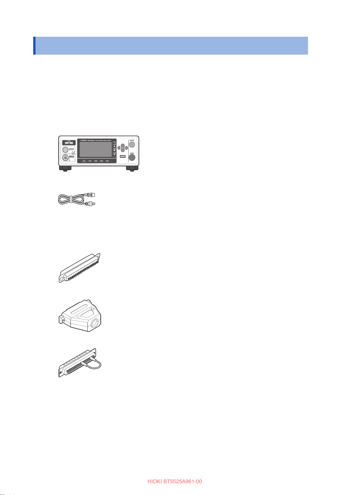
7.5 Accessory Connector Assembly
Procedure ..............................................96
7.6 Using Analog Output ............................97
Connecting an output cord ........................98
8 Communications
Function 99
8.1 Interface Overview and Features.....100
Remote state and local state ...................100
8.2 RS-232C Interface..............................101
Setting communications conditions..........101
Connecting the RS-232C cable ...............102
8.3 LAN Interface ......................................103
Settings for the communications
conditions ...............................................104
Setting the communications conditions ....106
Setting the LAN communications.............108
Enhancing the speed of LAN
communications......................................108
Connecting a LAN cable .........................109
8.4 USB Interface......................................110
Installing the USB driver..........................110
Connecting the USB cable ......................110
8.5 Automatically Sending the
Measured Value Every Time a Test
Is Completed (Auto Data Output
Function).............................................. 111
8.6 Communications Command
Display (Command Monitor
Function)..............................................112
8.7 Communications Method...................114
Message format......................................114
Output queue and input buer .................119
Status system.........................................119
Standard Event Status Register ..............121
Items restored to the default settings .......123
8.8 Communications Command List ......124
8.9 Communications Command
Reference ............................................130
5.4 Setting Whether to Turn ON or
OFF the Key Operation Sound...........67
5.5 Enabling/Disabling the Key
Operations.............................................68
Disabling the key operations (key lock)......68
Enabling the key operations (releasing
key lock)...................................................68
Enabling the key lock function with a
passcode..................................................69
Disabling the key lock function with a
passcode..................................................70
Releasing the key lock by entering the
passcode..................................................71
5.6 Adjusting the Screen Contrast............72
5.7 Adjusting the Backlight ........................73
5.8 Manually Setting the Frequency of
the Power Supply .................................74
5.9 Initializing the Instrument (Reset) ......75
6 Saving and Loading
Measurement
Conditions (Panel
Save and Load
Functions) 77
6.1 Saving Measurement Conditions
(Panel Save Function) .........................78
6.2 Loading Measurement Conditions
(Panel Load Function) .........................79
6.3 Changing the Panel Name..................80
6.4 Deleting Panel Data .............................81
7 External Control
(EXT. I/O) 83
7.1 External Input and Output
Terminals and Signals..........................85
Switching the current sink (NPN) and
current source (PNP) ................................85
Connector used and signal arrangement ...85
Signal functions ........................................86
7.2 Timing Chart..........................................87
7.3 Internal Circuit Conguration ..............91
HIOKI BT5525A961-00

Contents
5
Before requesting repair..........................195
10.3 Error......................................................197
10.4 License Information............................199
11 Appendix 201
11.1 Block Diagram.....................................201
11.2 Current Limit and Relationship
Between Measured Resistance
and Output Voltage ............................202
11.3 Inuence of Capacitive Load ............203
11.4 Inuence of Noise...............................205
11.5 Change in the Current Flowing
Through Insulators .............................207
11.6 LOW Terminal Side Test Lead
Fabrication...........................................208
Hioki LOW terminal side test lead
shielded cable construction .....................208
Processing the tip of the LOW terminal
side test lead ..........................................209
11.7 Rackmount Fittings ............................211
11.8 External View ......................................213
11.9 Default Setting ....................................214
Standard command ................................131
Event Register........................................133
Error.......................................................135
Measurement control ..............................135
Measurement command .........................136
Measured value output............................137
Measurement settings.............................140
Contact check.........................................145
BDD .......................................................146
Test time.................................................151
Comparator ............................................151
Saving and loading the measurement
conditions ...............................................154
System settings ......................................156
RS-232C ................................................161
LAN........................................................162
Communications settings ........................167
8.10 Communications Command
Examples.............................................170
9 Specifications 179
9.1 General specications .......................179
9.2 Input, Output, and Measurement
Specications......................................180
Basic specications ................................180
Accuracy Specications ..........................181
Functional specications .........................182
Interface specications............................186
Other Specications................................189
9.3 Specications of the Options ............190
L2130 Clip Type Lead .............................190
L2131 Clip Type Lead .............................190
L2132 Unterminated Lead.......................191
L2133 Unterminated Lead.......................191
L9094 Output Cord ................................192
L9637 RS-232C Cable............................192
10 Maintenance and
Service 193
10.1 Repairs, Inspections, and Cleaning.193
Calibration ..............................................193
Replaceable parts and service lives.........194
Cleaning.................................................194
Disposal .................................................194
10.2 Troubleshooting ..................................195
HIOKI BT5525A961-00

Contents
6
HIOKI BT5525A961-00

7
Introduction
Introduction
Thank you for choosing the Hioki BT5525 Battery Insulation Tester. To ensure your ability to get
the most out of this instrument over the long term, please read this manual carefully and keep it
available for future reference.
The latest edition of the instruction manual
The contents of this manual are subject to change, for example as a result of product
improvements or changes to specications.
The latest edition can be downloaded from Hioki’ s website.
https://www.hioki.com/global/support/download/
Product registration
Register this product in order to receive important product information.
https://www.hioki.com/global/support/myhioki/registration/
Refer to the following instruction manuals in accordance with your application.
Name of the instruction
manual Description Format
Instruction Manual
(this manual)
Includes overview of the instrument, operation
methods, function descriptions, and specications.
PDF le
(for web download)
Startup Guide Includes information for using the instrument safely,
basic operation methods, and specications (selected
relevant information).
Hard copy
Operating Precautions Information for using the instrument safely.
Please review the separate “Operating Precautions”
before using the instrument.
Hard copy
Intended audience
This manual has been written for use by individuals who use the product or provide information
about how to use the product.
In explaining how to use the product, it assumes electrical knowledge (equivalent of the
knowledge possessed by a graduate of an electrical program at a technical high school).
Trademarks
Microsoft, Windows, Visual Basic, Visual Studio, Visual C++, and Visual C# are either registered
trademarks or trademarks of Microsoft Corporation in the United States and other countries.
HIOKI BT5525A961-00

8
Checking Package Contents
When you receive the instrument, inspect it to ensure that no damage occurred during shipment.
Pay particular attention to included accessories, panel keys and switches, and terminals. If you
nd any damage or discover that the instrument does not perform as indicated in its specications,
please contact your authorized Hioki distributor or reseller.
Conrm the package contents.
BT5525 Battery Insulation Tester
Power cord
Startup Guide
Operating Precautions (0990A903)
EXT. I/O connector (male)
EXT. I/O connector cover
EXT. I/O interlock cancellation jig
HIOKI BT5525A961-00

9
Options
Options
The options listed below are available for the instrument. To order an option, please contact your
authorized Hioki distributor or reseller.
Options are subject to change. Check Hioki’s website for the latest information.
Model name Rated voltage Rated current Cable length
L2130 Clip Type Lead (red) 500 V 50 mA 1.5 m
L2131 Clip Type Lead
(black, special triaxial connector)
500 V 50 mA 1.5 m
L2132 Unterminated Lead (red) 500 V 50 mA 5 m
L2133 Unterminated Lead
(black, special triaxial connector)
500 V 50 mA 5 m
L9094 Output Cord (analog output) 30 V 0.5 A 1.5 m
L9637 RS-232C Cable (9-pin to 9-pin) – – 3 m
HIOKI BT5525A961-00

10
Symbols and Abbreviations
Safety
In this manual, the risk seriousness and the hazard levels are classied as follows.
DANGER Indicates an imminently hazardous situation that, if not avoided, will result in
death or serious injury.
WARNING Indicates a potentially hazardous situation that, if not avoided, could result in
death or serious injury.
CAUTION Indicates a potentially hazardous situation that, if not avoided, could result in
minor or moderate injury or potential risks of damage to the supported product
(or to other property).
IMPORTANT Indicates information or content that is particularly important from the
standpoint of operating or maintaining the instrument.
Indicates a high-voltage hazard.
Failure to verify safety or improper handling of the instrument could lead to
electric shock, burn injury, or death.
Indicates a prohibited action.
Indicates a mandatory action.
Symbols on the product
Indicates the presence of a potential hazard. For more information about locations where
this symbol appears on instrument components, see “Precautions for Use” (p. 14) and
warning messages listed at the beginning of operating instructions, and the accompanying
document entitled “Operating Precautions.”
Indicates that dangerous voltage may be present at this terminal.
Indicates the ON side of the power switch.
Indicates the OFF side of the power switch.
Indicates direct current (DC).
Indicates alternating current (AC).
Indicates a grounding terminal.
Indicates a ground terminal connected to the chassis of the instrument.
Symbols for various standards
Indicates that the product is subject to the Waste Electrical and Electronic Equipment (WEEE)
Directive in EU member nations. Dispose of the product in accordance with local regulations.
Indicates that the product complies with standards imposed by EU directives.
HIOKI BT5525A961-00

11
Symbols and Abbreviations
Others
* Indicates additional information is described below.
(p. ) Indicates the page number to reference.
[ ] Indicates the names of user interface elements on the screen.
MENU
(Bold letters) Indicates the names of the control keys.
Accuracy labeling
The instrument’s accuracy is expressed using a combination of the formats shown below.
• These formats dene limit values for errors using the same units as measured values.
• They dene a percentage of the reading, a percentage of full scale, a percentage of the setting,
or a limit value for errors in terms of digits.
Reading
(display value)
Indicates the value displayed by the instrument. Limit values for reading errors are
expressed as a percentage of the reading (“% rdg.”).
Full scale
(maximum
display value)
Indicates the scale length or maximum display value for each measurement range.
Measurement range values for the instrument indicates that scale length or maximum
display value. Limit values for full-scale errors are expressed as a percentage of full
scale (“% f.s.”).
Setting
(setting)
Indicates the voltage and current values specied to be output from the measuring
instrument. Limit values for setting errors are expressed as a percentage of the reading
(“% of setting”). Indicates the voltage, current, or other value that the instrument
has been congured to output. Limit values for setting errors are expressed as a
percentage of the setting
Digit
(resolution)
Indicates the minimum display unit (in other words, the smallest digit that can have a
value of 1) for a digital measuring instrument. Limit values for digit errors are expressed
using digits. Indicates the minimum display unit (in other words, the smallest digit that
can have a value of 1) for a digital measuring instrument. Limit values for digit errors
are expressed using digits
HIOKI BT5525A961-00

12
Safety Information
Safety Information
This instrument is designed to conform to IEC 61010 Safety Standards and has been thoroughly
tested for safety prior to shipment. However, using the instrument in a way not described in this
manual may negate the provided safety features.
Carefully read the following safety notes before using the instrument.
DANGER
Familiarize yourself with the instructions and precautions in this manual
before use.
Failure to do so could cause improper use of the instrument, resulting in serious
bodily injury or damage to the instrument.
WARNING
If you have not used any electrical measuring instruments before, you
should be supervised by a technician who has experience in electrical
measurement.
Failure to do so could cause the operator to experience an electric shock.
Moreover, it could cause serious events such as heat generation, re, and an arc
ash due to a short-circuit.
HIOKI BT5525A961-00

13
Safety Information
Measurement categories
IEC 61010 denes measurement categories to facilitate safe use of measuring instruments. Test
and measurement circuits designed to be connected to a main power supply circuit are classied
into three categories depending on the type of main power supply circuit.
DANGER
Do not use a measuring instrument for measurements on a mains
circuit that exceeds the range of the measurement category rated for
the instrument.
Do not use a measuring instrument without a measurement category
rating for measurements on a mains circuit.
Failure to observe this can cause a serious bodily injury and damage to the
instrument and other equipment.
Measurement
category II
(CAT II)
Applicable to test and measuring circuits connected directly to utilization points
(socket outlets and similar points) of a low-voltage MAINS installation.
Example: Measurements on household appliances, portable tools, and similar
equipment, and on the consumer side only of socket outlets in the xed
installation.
Measurement
category III
(CAT III)
Applicable to test and measuring circuits connected to the distribution part of the a
building’ s low-voltage MAINS installation.
Example: Measurements on distribution boards (including secondary meters),
photovoltaic panels, circuit breakers, wiring, including cables, bus-bars,
junction boxes, switches, and socket outlets in a xed installation, as
well as equipment for industrial use and some other equipment such as
stationary motors with permanent connection to the xed installation.
Measurement
category IV
(CAT IV)
Applicable to test and measuring circuits connected at the source of the a building’ s
low-voltage MAINS installation.
Example: Measurements on devices installed before the main fuse or circuit breaker
in the building installation.
Outlet
CAT II
Interior wiring
Service entrance
Service drop
CAT IV
Power meter
CAT III
Distribution panel
Fixed equipment
HIOKI BT5525A961-00

14
Precautions for Use
Precautions for Use
Be sure to follow the precautions listed below in order to use the instrument safely and in a manner
that allows it to function eectively.
Use of the instrument should conform not only to its specications, but also to the specications of
all accessories, options, and other equipment in use.
Installing the instrument
WARNING
Do not install the instrument in locations such as the following:
•In locations where it would be subject to direct sunlight or high temperatures
•In locations where it would be exposed to corrosive or explosive gases
•In locations where it would be exposed to powerful electromagnetic radiation or
close to objects carrying an electric charge
•Close to inductive heating devices (high-frequency inductive heating devices,
IH cooktops, etc.)
•In locations characterized by a large amount of mechanical vibration
•In locations where it would be exposed to water, oil, chemicals, or solvents
•In locations where it would be exposed to high humidity or condensation
•In locations with an excessive amount of dust
Doing so could damage the instrument or cause it to malfunction, resulting in bodily
injury.
CAUTION
Do not place the instrument on an unstable stand or angled surface.
Doing so could cause the instrument to fall or overturn, resulting in bodily injury or
damage to the instrument.
To prevent overheating, be sure to leave the specied clearances around the instrument.
• Place with its bottom side facing downward.
• Do not block vent openings.
50 mm 50 mm 50 mm
HIOKI BT5525A961-00

15
Precautions for Use
Check before use
DANGER
Inspect the instrument and verify proper operation before use.
Use of the instrument while it is malfunctioning could result in serious bodily injury.
If you nd any damage, contact your authorized Hioki distributor or reseller.
Handling the instrument
CAUTION
Do not subject the instrument to vibration or mechanical shock while
transporting or handling it.
Do not drop the instrument.
Doing so could damage the instrument.
Do not short-circuit the output terminal or input a voltage to the output terminal.
The instrument is classied as a Class A device under the EN 61326 standard.
Use of the instrument in a residential setting such as a neighborhood could interfere with reception of
radio and television broadcasts. If you encounter this issue, take steps as appropriate to address it.
Shipping Precautions
Store the instrument packaging material after opening the instrument. Use the original packaging
when shipping the instrument.
Hioki cannot be responsible for damage that occurs during shipment.
HIOKI BT5525A961-00

16
Precautions for Use
Handling the test leads
DANGER
Do not use test leads whose insulation is damaged or whose metal
portion is exposed.
Doing so could cause serious bodily injury.
WARNING
When using the instrument while connected to test leads, use the lower
of the ratings indicated on the instrument and on the test leads.
Using the instrument to make measurements that exceed either rating could cause
the operator to experience an electric shock.
When using this instrument, use only Hioki specied test leads.
Using a test lead other than the specied parts could result in bodily injury or a short-
circuit.
CAUTION
Do not step on cords or allow them to become caught between other objects.
Doing so may damage insulation, resulting in an electric shock.
Do not bend or pull on cables at temperatures of 0°C or lower.
The cable is hardened. Doing so could damage the insulation or cause a wire break,
resulting in an electric shock.
Do not bend, pull on, or twist cables, including where they connect, with
excessive force.
Doing so could cause a wire break.
HIOKI BT5525A961-00

17
1Overview
1.1 Product Overview
This instrument is an insulation resistance tester that generates DC voltage and tests the insulation
resistance of instruments, parts, batteries, etc.
It’s capable of high-speed testing using user-congured test voltages. With the Break Down Detect
(BDD) function, micro short circuits and contaminations (metal foreign substances) can be detected
during an insulation resistance test before battery liquid injection. In addition, this instrument
can be widely used from manufacturing/test lines for research and development since ample
communications interfaces are provided as standard equipment.
1.2 Features
BDD function for detecting micro insulation failure, contamination, etc. (p. 60)
Any small change to the voltage and current during a test can be captured and micro insulation
failure due to contamination can be detected.
High-speed test
Test results are displayed within 2 PLCs + calculation time at full speed.
Flexible test settings
Measurement and charging current limit function (p. 64)
Since the charging current can be limited as desired from 50 μA to 50 mA, settings can be adjusted
to yield the optimal test time for the device under test (DUT) that has a capacitive load.
Test voltage (p. 34)
Any test voltage can be set between 25 V and 500 V with a resolution of 1 V. With the comparator
function (p. 44) and test time function (p. 40), insulation resistance tests can be performed
based on various standards.
Contact check function for detecting contact defects and broken connections of wiring (p. 58)
The contact condition is checked by monitoring the electrostatic capacitance between test points.
This function helps improve the test quality.
Automatic discharge function (p. 56)
After the test, the electric charge stored in the DUT is discharged inside of the instrument, which
can prevent any damage to other instrument at the next test.
Wide range of communications interface choices
LAN, RS-232C, and USB connections are provided with the instrument as standard equipment. A
personal computer (PC) and programmable logic controller (PLC) can be connected to import the
instrument controls and test results. In addition, an EXT. I/O connection is also installed and the
controls of the measuring instrument, instrument status, and judgment results can be imported.
1 Overview
Overview
HIOKI BT5525A961-00

18
Part Names and Functions
1.3 Part Names and Functions
Front
2244
77991010
55
66
11
88
33
11TEST indicator Lights up when a hazardous voltage is applied to the measurement
terminals.
p. 49
22Display Monochrome graphic LCD p. 21
33COMP lamp Displays the judgment result of a measured value when the
comparator function is selected.
U. FAIL Measured value > Upper limit value
PASS Lower limit value ≤Measured value
≤ Upper limit value (within the judgment reference)
L. FAIL Measured value < Lower limit value
p. 44
44Cursor key Moves over the items displayed in the screen display. –
55START key Starts an insulation resistance test. p. 49
66STOP key Stops the insulation resistance test.
Cancels the conguration process and returns to the measurement
screen.
p. 55
77ENTER key Conrms the items displayed in the screen display. –
88Fkey Selects the items displayed in the screen display. –
99MENU key Displays the setting screens and switches the page. –
1010 Measurement
terminals
Connects a test lead. p. 30
This instrument can be mounted on a rack. Keep any parts removed from the instrument in a safe place in
case you need to use them again.
See “11.7 Rackmount Fittings” (p. 211) , “11.8 External View” (p. 213)
HIOKI BT5525A961-00

19
Part Names and Functions
Rear
113344
1010 99886611111212
55
22
77
11POWER switch Switches the ON/OFF setting of the instrument power. p. 28
22Power supply inlet Connects the power cord provided with the instrument. p. 28
33Vent Ventilates the instrument to prevent the temperature of the
inside from going up excessively.
p. 14
44GND terminal (functional
ground terminal)
Connects the instrument to the ground. –
55EXT. I/O connector Used to externally control the instrument. p. 83
66Serial No. The serial number consists of nine digits. The rst two
digits indicate the year of manufacture, while the second
two digits indicate the month of manufacture. Do not
remove this sticker as the number is important.
p. 23
77MAC address MAC address of LAN. It is required for instrument control.
Do not remove it.
–
88EXT. I/O MODE switch
(NPN/PNP)
Switches the type of PLC (programmable logic controller)
to be connected to the EXT. I/O.
p. 85
99LAN connector LAN (socket communications) enables the PC to control
the instrument. Measurement data can be transferred to
the PC.
p. 103
1010 USB connector USB communications (virtual COM port) enables the
PC to control the instrument. Measurement data can be
transferred to the PC.
p. 110
1111 RS-232C connector RS-232C communications (serial communications)
enables the PC to control the instrument. Measurement
data can be transferred to the PC.
p. 101
1212 ANALOG OUTPUT terminal Outputs measured values in analog. p. 97
Overview
HIOKI BT5525A961-00

20
Part Names and Functions
Right side
Vent
Stand
Left side
Stand
Support
foot
Stand
Bottom
Stand
Using the instrument with the stands
Unfold the stands all the way.
Be sure to unfold both of the stands.
Closing the stands
Fold the stands all the way.
CAUTION
Do not subject the instrument to excessive force from above when the stands
are extended.
Doing so could damage the stands.
HIOKI BT5525A961-00
Other manuals for BT5525
2
Table of contents
Other Hioki Test Equipment manuals

Hioki
Hioki IR4051 User manual

Hioki
Hioki BT3564 User manual

Hioki
Hioki 3550 User manual

Hioki
Hioki 3665-20 User manual

Hioki
Hioki HiTESTER 3540 User manual

Hioki
Hioki 3805-50 User manual

Hioki
Hioki 9455 User manual

Hioki
Hioki IR3455-01 User manual

Hioki
Hioki BT3554 User manual

Hioki
Hioki 3169-20 Instruction manual