Hioki 3169-21 Instruction manual

CLAMP ON POWER
QUICK START MANUAL
3169-20/21
HiTESTER


i
Contents
1
2
3
4
5
6
7
8
9
10
11
APPX
IDX
Contents
Introduction .................................................................. 1
Safety Notes ................................................................ 1
1 Parts Names 3
1.1 Instrument Labels and Functions ....................... 4
1.2 Screen Names and Display Elements ................ 8
1.2.1 Screen Configuration ...........................................8
1.2.2 Common Display .................................................9
1.2.3 On-Screen Indicators .........................................10
2 Power Measurement 11
2.1 Outline .............................................................. 11
2.2 Measurement Procedure .................................. 13
2.3 Measurement Preparations .............................. 14
2.4 Connect to the Line to be Measured ................ 18
2.5 Perform Measurement ...................................... 26

ii Quick Start Manual
Contents

1
1
2
3
4
5
6
7
8
9
10
11
Introduction
• The 3169-20/21 CLAMP ON POWER HiTESTER is supplied
with a instruction manual in addition to this manual. Please be
sure to read both manuals.
• This manual is a quick reference source with examples and infor-
mation regarding the setting-up of and key operation for the
3169-20/21 CLAMP ON POWER HiTESTER for measurement
purposes.
• For current input with this device, a clamp-on sensor (optional) is
required. For details, refer to the instruction manual for the
clamp-on sensor you are using.
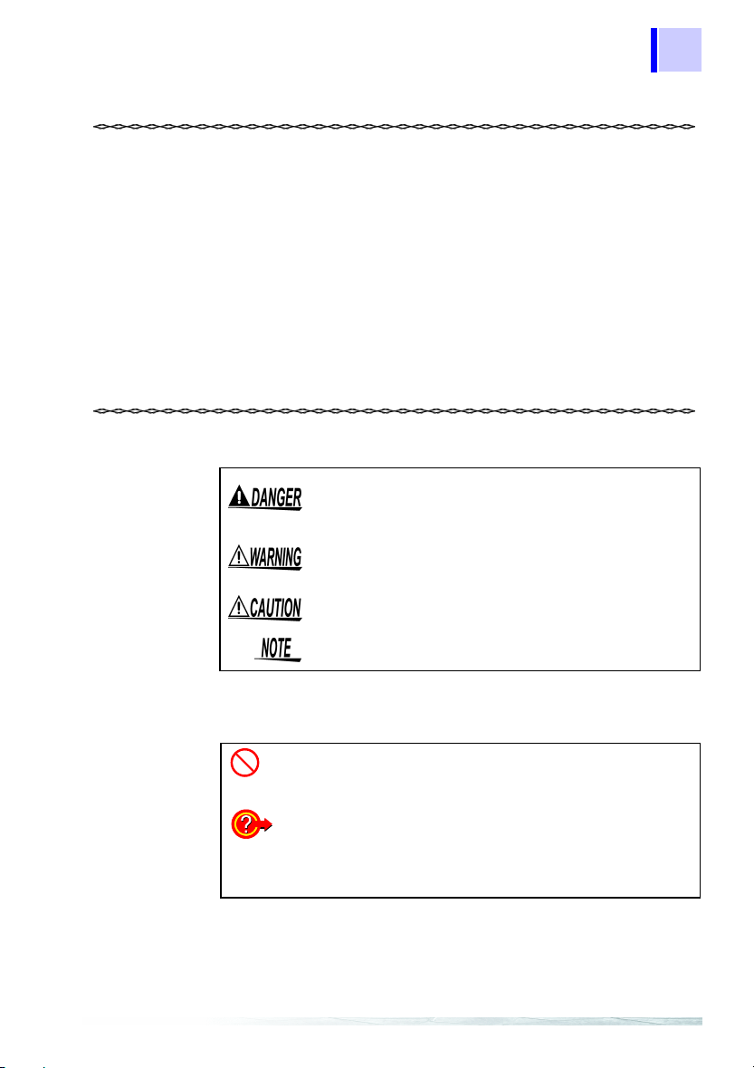
Safety Notes
The following symbols in this manual indicate the relative impor-
tance of cautions and warnings.
Other Symbols
Indicates that incorrect operation presents an
extreme hazard that could result in serious injury or
death to the user.
Indicates that incorrect operation presents a signifi-
cant hazard that could result in serious injury or
death to the user.
Indicates that incorrect operation presents a possi-
bility of injury to the user or damage to the product.
Advisory items related to performance or correct
operation of the product.
Indicates the prohibited action.
❖Indicates the reference.
Indicates quick references for operation and reme-
dies for troubleshooting.
*Indicates terminology explained at the bottom of
the page.

2Quick Start Manual

3
1
2
3
4
5
6
7
8
9
10
11
Parts Names 1
The reference pages referred to above are those in the instruction
manual.
❖4 "Connecting to Lines to be Measured" (page 35)
RS-232C
D/A output
(3169-21)
Printer
PC
❖9 "Using the Instrument with
a Computer" (page 145)
❖3 "Measurement Preparations"
(page 25)
*: The RS-232C is connected to a printer or PC.
EXT I/O
❖10 "Using the External Input/
Output Terminal" (page 151)
❖8 "Using a Printer"
(page 137)
❖11 "Using D/A Output (3169-21 only)"
(page 157)
❖7.2 "Using a PC Card"
(page 117)
PC card
Recorder, logger

4
1.1 Instrument Labels and Functions
Quick Start Manual
1.1 Instrument Labels and Functions
Display
5.7-inch STN LCD
Function (F1-F5) keys
Selects or switches the screens
and setting items.
Cursor key
These keys move the cur-
sor on the screen.
Front Panel

1.1 Instrument Labels and Functions
5
1
2
3
4
5
6
7
8
9
10
11
MEASURE key
Switches to a screen that displays measurements.
SET UP key
Switches to a screen that displays settings.
FILE key
Used to work on files.
IRANGE key
Sets the current measurement range for the circuit
to be measured on-screen.
URANGE key
Sets the voltage measurement range.
SAVE key
Enables the manual saving of measurement data
on the PC card or in internal memory. Manual sav-
ing is not possible during time-series measurement.
COPY key
Outputs screen image data to the PC card, internal
memory, or a printer.
START/STOP key
Starts or stops time-series measurements including
integration measurement.
START/STOP LED
Flashes in green while the instrument is standing by
for time-series measurement, and lights in green
while the instrument is performing time-series mea-
surement.
Front Panel Enhanced View

6
1.1 Instrument Labels and Functions
Quick Start Manual
Current Input terminals
Connect an optional clamp-on sensor.
Voltage Input terminals
Connect the supplied 9438-03 VOLTAGE CORD.
CH1 CH2 CH3 CH4
Black Red Yellow Blue
NU
1U2U3
Top Panel
AC Power Inlet
Connects the power cord.
The supply voltage ranges
from 100 V to 240 V.
POWER switch
Turns the instrument on and off.
: Power OFF
: Power ON
Contrast Control Knob
(CONTRAST)
Adjusts the contrast of the screen.
KEY LOCK switch
Sliding this switch in the direction of the
arrow disables all key operation except
the POWER switch.
Left Panel

1.1 Instrument Labels and Functions
7
1
2
3
4
5
6
7
8
9
10
11
PC Card slot
A PC Card can be
inserted here.
Eject button
Press this button to eject a
PC Card from the slot.
RS-232C Interface connector
Connects to a PC or printer using
an RS-232C cable.
External Input/Output Terminal (EXT I/O)
Connects the optional 9440 connection cable.
Used to start and stop time-series measurement,
and control data storage on the PC card.
D/A Output Terminal
(D/A OUT)
Installed in the 3169-21
only. Connects the sup-
plied 9441 connection ca-
ble. Used for analog
output.
Right Panel
Number plate
Contains manufacturer’s ID
numbers. Please do not re-
move, as this information is
reguired for product man-
agement.
Rear Panel

8
1.2 Screen Names and Display Elements
Quick Start Manual
1.2.1 Screen Configuration
The screens are divided into three basic types: measurement
screens, setting screens, and file screens. Each screen is selected
using three panel keys: MEASURE, SET UP
, and FILE.
1.2 Screen Names and Display Elements
Measurement screen
Setting screen
MAIN
POWER
INTEGRATE
DEMAND
ZOOM
HARMONIC LIST
HARMONIC GRAPH
WAVEFORM
WIRING CHECK
WIRING DIAGRAM
MEASUREMENT
DATA OUTPUT
SAVE, PRINT ITEMS
SYSTEM
D/A OUTPUT (3169-21 only)
INTERNAL SETTINGS
INTERNAL MEMORY
PC CARD
FIRMWARE UPDATE
File screen

1.2 Screen Names and Display Elements
9
1
2
3
4
5
6
7
8
9
10
11
1.2.2 Common Display
This section of the screen shows information common to all mea-
surement screens (except the zoom screen and the wiring diagram
screen).
Time Displays the current time.
Range Displays the voltage range and current range of
the on-screen circuit. The VT(PT) ratio and CT
ratio are shown under these ranges. The current
range and CT ratio of I4 are shown only when
3P4W4I is set as the wiring method.
Wiring Displays the wiring method set on the setting
screen.
No. of circuits Displays the number of circuits to be measured
as set on the setting screen.
Synchroniza-
tion
method
Displays the synchronization method and fre-
quency of the line to be measured as set on the
setting screen.
Interval Displays the interval set on the setting screen.
Common Display
Time
Range
Wiring
No. of circuits
Synchroniza-
tion method
Interval

10
1.2 Screen Names and Display Elements
Quick Start Manual
1.2.3 On-Screen Indicators
Goes on when the reactive-power-meter method is
ON.
Goes on when the displayed measurement is held.
Goes on when the medium for saving data is set to
PC card. Flashes when the PC card is accessed.
Goes on when the medium for saving data is set to
internal memory. Flashes when the internal memory
is accessed.
Goes on when the PC card or internal memory is full.
Goes on when the device to be connected to the RS-
232C is set to PC.
Goes on when the device to be connected to the RS-
232C is set to printer.
Goes on when the PLL is unlocked; the synchroniza-
tion method is automatically switched over to the
fixed clock.
Goes on when the keys are locked.
Goes on when the voltage or current dynamic range
is exceeded.
Displayed when the range is exceeded.
U3* and I3* indicate that the data is obtained by calculating the 2-volt-
age, 2-current measurement results when 3P3W2M (three-phase, 3-
wire, 2-power-meter method) is selected.
❖Instruction manual "Appendix" (page 195)

2.1 Outline
11
1
2
3
4
5
6
7
8
9
10
11
This chapter explains setting and measurement procedures using
the following conditions.
Instrument and Accessories Required for Measurement
Power Measurement 2
2.1 Outline
Measure the power of a Three-phase 3-wire line for 7 days.
Measurement location:
A Tree-phase 3-wire 200 V line of a switchboard (50 Hz, 50 A load)
Setting:
Time-series measurement start time: 2002/06/20 08:00
Time-series measurement stop time: 2002/06/27 08:00
Data is automatically output to the PC card at 5-minute intervals.
Average value (voltage, current, and power) and integrated power are
stored on the PC card. The reactive power-meter method is not used.
A
B
C
Black
Red
Yellow
9438-03 VOLTAGE CORD 9661 CLAMP ON SENSOR
Upper side of the
3169-20/21
Face the arrow toward the Load
SOURCE
LOAD
Power cord
9438-03 VOLTAGE CORD
1 set (4 cords)(One each red, yellow,
blue, and black cords.)
3169-20/21
PC card
9661 CLAMP ON SENSOR
x 2

12
2.1 Outline
Quick Start Manual
Setting Screens under the Example Conditions
<MEASUREMENT>
WIRING : 3P3W2M
(Three-phase 3-wire,
2-power-meter method)
Number of circuits : X 1 (1 circuit)
SAMPLING : PLL
Measured frequency: 50 Hz
VAR METHOD : OFF
AVERAGE TIMES : 1
VOLTAGE RANGE : 300 V
VT (PT) : 0001.00
CURRENT RANGE : 50 A
CT : 0001.00
SENSOR : 9661
ÅîéûånóÒê›íËâÊñþÅî
<DATA OUTPUT>
MEAS. START : TIME
(2002/06/20 08:00)
MEAS. STOP : TIME
(2002/06/27 08:00)
INTERVAL TIME : 5 min
SAVE IN... : PC CARD
DATA FILE NAME : INTEG
<SAVE, PRINT ITEMS>
NORM. MEAS.: ON
HARMONIC : OFF
INTEG. & DEM.: ON
INST. : OFF
AVE. : ON
MAX. : OFF
MIN. : OFF

2.2 Measurement Procedure
13
1
2
3
4
5
6
7
8
9
10
11
2.2 Measurement Procedure
1. Setting the wiring details
2. Displaying the Wiring Diagram
3. Connectting the voltage cords and
clamp-on sensor to the line to be
measured
4. Checking the Wiring
Connect to the
Line to be
Measured
(page 18)
1. Connecting the Power Cord
2. Connecting the Voltage Cords
3. Connecting the Clamp-On Sensor
4. Inserting a PC Card
5. Turning the Power On
Measurement
Preparations
(page 14)
1. Setting the measurement conditions
2. Confirm range
3. Start measurement
4. Stop measurement
Shutdown Procedure
1. Disconnect the voltage cords and
clamp-on sensor from the measured
line.
2. Turn off the power to the 3169-20/
21.
3. Disconnect the power cord from the
AC outlet.
4. Remove the PC card from the 3169-
20/21 and analyze the saved data
on PC.
Perform
Measurement
(page 26)

14
2.3 Measurement Preparations
Quick Start Manual
2.3 Measurement Preparations
• Before turning the product on, make sure the source volt-
age matches that indicated on the product's power connec-
tor. Connection to an improper supply voltage may damage
the product and present an electrical hazard.
• To avoid electric shock and ensure safe operation, connect
the power cable to a grounded (3-contact) outlet.
1. Connecting the Power Cord
1. Connect the power cord to
the AC power inlet.
2. Plug the power cord into the
AC mains outlet.
1
2

2.3 Measurement Preparations
15
1
2
3
4
5
6
7
8
9
10
11
Connect the voltage cords to the product first, and then to
the active lines to be measured. Observe the following to
avoid electric shock and short circuits.
• Voltage cord should only be connected to the secondary
side of a breaker, so the breaker can prevent an accident if
a short circuit occurs. Connections should never be made
to the primary side of a breaker, because unrestricted cur-
rent flow could cause a serious accident if a short circuit
occurs.
• Do not allow Do not allow the voltage cable clips to touch
two wires at the same time. Never touch the edge of the
metal clips. Never touch the edge of the metal clips.
• Voltage input terminals U1, U2, and U3are common to the N
terminal and are not insulated. To avoid the risk of electric
shock, do not touch the terminals.
• For safety reasons, when taking measurements, only use the
9438-03 VOLTAGE CORD provided with the product.
• The supplied voltage cords consist of one each red, yellow, blue
and black cords. Connect only the cords actually needed for
measurement. Cords not being used for measurement should
be disconnected.
2. Connecting the Voltage Cords
Red Voltage input terminals
Connect the 9438-03 VOLTAGE
CORD to the voltage input termi-
nals of the 3169-20/21.
Insert plugs all the
way in.
Black Yellow

16
2.3 Measurement Preparations
Quick Start Manual
Connect the clamp-on sensors to the product first, and then
to the active lines to be measured. Observe the following to
avoid electric shock and short circuits.
• Clamp sensor should only be connected to the secondary
side of a breaker, so the breaker can prevent an accident if
a short circuit occurs. Connections should never be made
to the primary side of a breaker, because unrestricted cur-
rent flow could cause a serious accident if a short circuit
occurs.
• When the clamp sensor is opened, do not allow the metal
part of the clamp to touch any exposed metal, or to short
between two lines, and do not use over bare conductors.
• To prevent damage to the product and sensor, never con-
nect or disconnect a sensor while the power is on.
• The current input terminals of the 3169-20/21 are not insu-
lated. To avoid the risk of electric shock, only use the spec-
ified optional clamp-on sensor.
When disconnecting the BNC connector, be sure to release the
lock before pulling the connectors apart. Forcibly pulling the con-
nector without releasing the lock, or pulling on the cable, can
damage the connector.
3. Connecting the Clamp-On Sensor
Lock
BNC plug slots
3169-20/21 Current input
terminal
connector guide pins
Red Current input terminas
Connect the 9661 CLAMP ON
SENSOR to the current input ter-
minals of the 3169-20/21.
Align the slots in the BNC plug
with the guide pins on the connec-
tor at the instrument side, then
push and turn the plug clockwise.
(to unplug the connector, push the
plug and turn it counterclockwise
before pulling it apart.)
Yellow
This manual suits for next models
1
Table of contents
Other Hioki Test Equipment manuals
Popular Test Equipment manuals by other brands

Cleerline
Cleerline SSF-TKITP-500 quick start guide

Bacharach
Bacharach Leakator 10 Specifications

GAI-Tronics
GAI-Tronics 530FB manual

Conrad
Conrad energy 1509163 operating instructions

Accles & Shelvoke
Accles & Shelvoke CASH Stun Check Product data sheet

Agilent Technologies
Agilent Technologies 16452A Operation and service manual