Hioki IR4057-50 User manual

IR4053
IR4055
IR4056
IR4057-50
IR4053-10
IR4055-11
IR4056-20
IR4056-21
IR4053
IR4055
IR4056
IR4057-50
IR4053-10
IR4055-11
IR4056-20
IR4056-21
EN
EN
Instruction Manual
May 2021 Revised edition 1
IR4057B961-01 21-05H
(IR4052C960-01)
INSULATION TESTER
Instruction Manual
May 2021 Revised edition 1
IR4057B961-01 21-05H
(IR4052C960-01)
INSULATION TESTER
HIOKI IR4057B961-01

HIOKI IR4057B961-01

Model-specic functionality
The following functionality is available on a model-
specific basis:
: Supported –: Not supported
Functionality
Models
(As shown on instrument) See
IR4053 IR4055 IR4056 IR4057-50
Displaying 1-minute Values – – – p. 37
Negative Voltage
Notication – – p. 40
Low Resistance
Measurement – – p. 42
PVΩMeasurement – – p. 44
Wireless Communications
(GENNECT Cross) ––*p. 51
Wireless Communications
(HID function) ––– *p. 55
*: Z3210 Wireless Adapter (option) required.
IR4057B961-01
HIOKI IR4057B961-01

HIOKI IR4057B961-01

i
Contents
Introduction.........................................................................1
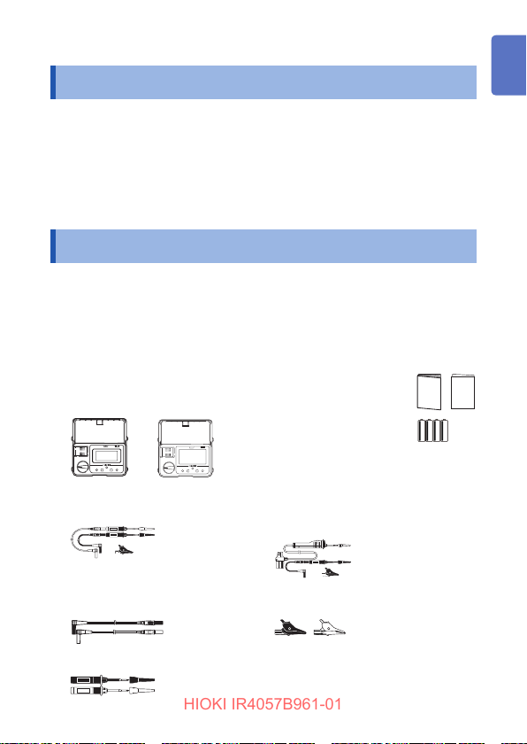
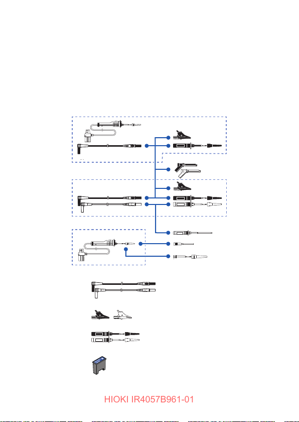
Verifying Package Contents ..............................................1
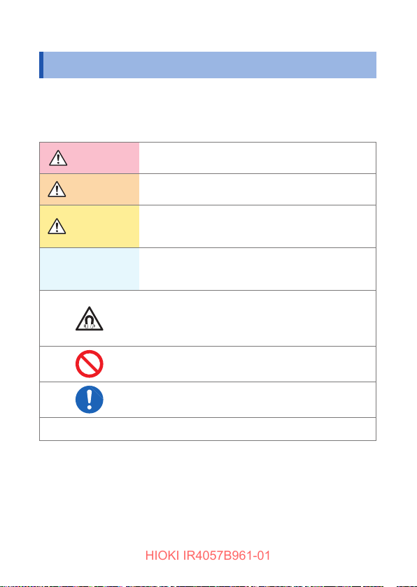
Notations.............................................................................4
Safety Information..............................................................7
Operating Precautions.......................................................9
1 Overview 13
1.1 Product Overview..........................................13
1.2 Names and Functions of Parts ....................14
2 Preparing for Measurement 21
2.1 Replacing Batteries or Fuse.........................22
2.2 Using the L9788-10 Test Lead with
Remote Switch (Red) ....................................25
2.3 Installing the Z3210 Wireless Adapter
(IR4057-50 only).............................................27
3 Measurement 29
3.1 Pre-measurement Inspection.......................29
3.2 Auto Power Save (Power-Saving Function)30
3.3 Auto Backlight-off (Automatic Light-off
Function)........................................................30
3.4 Comparator Function....................................31
Setting the Comparator............................................. 32
Canceling the Comparator........................................33
3.5 Insulation Resistance Measurement ...........34
Lock Function ........................................................... 35
Measuring Insulation Resistance..............................36
Displaying 1-minute Values (IR4057-50 only)...........37
Voltage Characteristics of Measurement Terminals.. 38
1
2
3
4
5
6
7
Appx.
索引
HIOKI IR4057B961-01

ii
Contents
3.6 Discharging Function ...................................39
3.7 Voltage Measurement ...................................40
Negative Voltage Notication Function
(IR4053 and IR4055 only)......................................... 41
3.8 Low Resistance Measurement
(IR4056 and IR4057-50 only).........................42
3.9 PVΩMeasurement Function
(IR4053 and IR4055 only)..............................44
3.10 Wireless Communications Function ..........51
Using the GENNECT Cross
(IR4055 and IR4057-50 only) ...................................51
Excel®Direct Input Function (HID function)
(IR4057-50 only) ....................................................... 55
4 Specications 59
4.1 GeneralSpecications .................................59
4.2 BasicandAccuracySpecications.............61
4.3 Functionalityspecications.........................69
Power-on Options ..................................................... 70
5 Maintenance and Service 71
5.1 Troubleshooting ............................................72
Errors and status codes............................................77
Appendix Appx.1
Appx. 1 Measurement Principles ..................Appx.1
Appx. 2 Operation Uncertainty...................... Appx.2
Appx. 3 Insulation Resistance Measurements
for Solar Cell Array ...........................Appx.3
HIOKI IR4057B961-01

1
Introduction
Introduction
Thank you for choosing the Hioki IR4053-10, IR4055-11, IR4056-20,
IR4056-21, and IR4057-50 Insulation Tester. To ensure your ability
to get the most out of this instrument over the long term, please
read this manual carefully and keep it available for future reference.
Hereinafter, the descriptions refer to models as shown on the
instrument.
Verifying Package Contents
When you receive the instrument, inspect it carefully to ensure that no
damage occurred during shipping. In particular, check the accessories,
panel switches, and connectors. If damage is evident, or if it fails to
operate according to the specications, contact your authorized Hioki
distributor or reseller. Conrm that these contents are provided.
□Insulation Tester
IR4053, IR4055
IR4056 IR4057-50
□
□
Instruction Manual
Operating Precautions
(0990A907)
□LR6 Alkaline battery × 4
□Neck strap
□L9787 Test Lead
(IR4053-10 and IR4056-20 only)
□L9788-11 Test Lead Set with
Remote Switch
(IR4055-11 and IR4056-21 only)
□L4930 Connection Cable Set
(IR4057-50 only)
□L4935 Alligator Clip Set
(IR4057-50 only)
□L4938 Test Pin Set (IR4057-50 only)
1
2
3
4
5
6
7
付録索引
HIOKI IR4057B961-01

2
Verifying Package Contents
Options
The options listed below are available for the instrument. To order
an option, please contact your authorized Hioki distributor or
reseller.
Options are subject to change. Please check Hioki's website for the
latest information.
56
4
3
2
1
7
8
9
10
11
HIOKI IR4057B961-01

3
Verifying Package Contents
Model Maximum rated voltage and
maximum rated current
1L9788-11 Test Lead Set with
Remote Switch CAT III 600 V/CAT II 600 V, 2 A
2
9804-01 Magnet Adapter (Red)
9804-02 Magnet Adapter (Black)
(φ11 mm, standard screw: M6 pan
head screw)
CAT IV 1000 V, 2 A
3L9787 Test Lead (1.2 m) CAT III 600 V/CAT II 600 V, 10 A
4L9787-91 Breaker Pin CAT III 600 V, 10 A
5L9788-10 Test Lead with Remote
Switch (Red) CAT III 600 V/CAT II 600 V, 2 A
6L9788-92 Breaker Pin CAT III 600 V, 2 A
7L9788-90 Tip Pin CAT III 600 V/CAT II 600 V, 2 A
8L4930 Connection Cable Set
(1.2 m) CAT IV 600 V/CAT III 1000 V, 10 A
9L4935 Alligator Clip Set CAT IV 600 V/CAT III 1000 V, 10 A
10 L4938 Test Pin Set CAT III 600 V/CAT II 600 V, 10 A
11 Z3210 Wireless Adapter
(for IR4057-50) –
1
2
3
4
5
6
7
付録索引
HIOKI IR4057B961-01

4
Notations
Notations
Safety notations
In this document, the severity levels of risk and hazard are classied
as follows.
DANGER Indicates an imminently hazardous situation that will
result in death or serious injury to the operator.
WARNING Indicates a potentially hazardous situation that may
result in death or serious injury to the operator.
CAUTION
Indicates a potentially hazardous situation that may
result in minor or moderate injury to the operator or
damage to the instrument or malfunction.
IMPORTANT
Indicates information or content that is particularly
important from the standpoint of operating or
maintaining the instrument.
Indicates a strong magnetic-eld hazard.
The effects of the magnetic force can cause
abnormal operation of heart pacemakers and/or
medical electronics.
Indicates prohibited actions.
Indicates the action which must be performed.
*Additional information is presented below.
HIOKI IR4057B961-01

5
Notations
Symbols on the instrument
Indicates cautions and
hazards. When the symbol
is printed on the instrument,
refer to a corresponding
topic in the Instruction
Manual.
Indicates that dangerous
voltage may be present at
this terminal.
Indicates a instrument
that has been protected
throughout by double
insulation or reinforced
insulation.
Indicates a grounding
terminal.
Indicates DC (Direct
Current).
Indicates AC
(Alternating Current).
Do not use in distribution
systems with voltage
higher than 660 V AC.
Symbols for various standards
Indicates the Waste Electrical and Electronic Equipment
Directive (WEEE Directive) in EU member states.
Indicates that the product conforms to regulations set out by the
EU Directive.
Screen Display
The instrument screen displays the alphanumeric characters as follows.
1 2 3 4 5 6 7 8 9 0
A B C D E F G H I J K L M N O P Q R S T U V W X Y Z
1
2
3
4
5
6
7
付録索引
HIOKI IR4057B961-01

6
Notations
Accuracy
Hioki expresses accuracy as error limit values specied in terms of
percentages of reading and digits.
Reading
(Displayed value)
Refers to the displayed value of the measuring
instrument. The limit values of reading errors are
expressed in percent of reading (% of reading, % rdg).
Digits
(Resolution)
Refers to the smallest change in the indication on the
digital measuring instrument, i.e., the numeral one in
the rightmost place. The limit values of digit errors are
expressed in terms of digits (dgt).
Trademarks
• The Bluetooth®word mark and logos are registered trademarks
owned by Bluetooth SIG, Inc. and any use of such marks by
Hioki E.E. Corporation is under license.
Other trademarks and trade names are those of their respective
owners.
• Microsoft Excel is either registered trademarks or trademarks of
Microsoft Corporation in the United States and other countries.
HIOKI IR4057B961-01

7
Safety Information
Safety Information
This instrument is designed to conform to IEC 61010 Safety
Standards, and has been thoroughly tested for safety prior
to shipment. However, using the instrument in a way not
described in this manual may negate the provided safety
features.
Before using the instrument, be certain to carefully read the following
safety notes:
DANGER
Mishandling during use could result in injury or death,
as well as damage to the instrument. Be certain that
you understand the instructions and precautions in
the manual before use.
WARNING
Protective gear
Performing measurement using this instrument
involves live-line work. To prevent an electric shock,
use appropriate protective insulation and adhere to
applicable laws and regulations.
1
2
3
4
5
6
7
付録索引
HIOKI IR4057B961-01

8
Safety Information
Measurement Categories
To ensure safe operation of measuring instruments, IEC 61010
establishes safety standards for various electrical environments,
categorized as CAT II to CAT IV, and called measurement categories.
DANGER
•Using a measuring instrument in an environment
designated with a higher-numbered category than
that for which the instrument is rated could result in
a severe accident, and must be carefully avoided.
•Never use a measuring instrument that lacks
category labeling in a CAT II to CAT IV measurement
environment. Doing so could result in a serious
accident.
This instrument conforms to the safety requirements for CAT III 600 V
measuring instruments.
CAT II: When directly measuring the electrical outlet receptacles of the
primary electrical circuits in equipment connected to an AC electrical
outlet by a power cord (portable tools, household appliances, etc.)
CAT III: When measuring the primary electrical circuits of heavy equipment
(xed installations) connected directly to the distribution panel, and
feeders from the distribution panel to outlets.
CAT IV:
When measuring the circuit from the service drop to the service
entrance, and to the power meter and primary overcurrent
protection device (distribution panel).
T Outlet
CAT II
Internal wiring
Distribution panel
Service entrance
Service drop
CAT IV
Power meter
CAT III
Fixed installation
HIOKI IR4057B961-01

9
Operating Precautions
Observe the following precautionary information to ensure that the
instrument can be used safely and in a manner that allows it to
perform as described in its specications.
Use of the instrument should conrm not only to its specications,
but also to the specications of all accessories, options, batteries,
and other equipment in use.
DANGER
•For your safe operation, do not connect any test
lead to the primary of the distribution panel.
•Do not short-circuit two wires to be measured by
bringing the test leads into contact with them. Arcs
or such grave accidents are likely to occur.
•To avoid short circuit or electric shock, do not touch
the metal part of the connecting test lead tip.
•To avoid electric shock, be careful to avoid shorting
live lines with the test leads tip.
If the test lead or the instrument is damaged, there
is a risk of electric shock. Perform the following
inspection before using them:
•Before using the instrument check that the coating
of the test leads are neither ripped nor torn and that
no metal parts are exposed. Using the instrument
under such conditions could result in electric
shock. Replace the test leads with those specied
by Hioki.
•Verify that the instrument operates normally to
ensure that no damage occurred during storage
or shipping. If you nd any damage, contact your
authorized Hioki distributor or reseller.
1
2
3
4
5
6
7
付録索引
HIOKI IR4057B961-01

10
Operating Precautions
WARNING
To avoid electric shock, short circuits and damage to
the instrument, observe the following precautions:
•Check the position of the rotary switch before
taking measurements.
•Disconnect the test leads from the measuring object
before switching the rotary switch.
•Do not use the instrument with circuits that exceed
its ratings or specications. Doing so may damage
the instrument, resulting in electric shock.
•Use only the specied test leads. Use of any test
lead not specied by Hioki does not allow safe
measurements.
•To prevent electrical accidents, turn off the circuit
before connecting the test leads.
• To avoid electric shock, do not exceed the lower of
the ratings shown on the instrument and test leads.
CAUTION
• The cable is hardened under the 0°C or colder
environment. Do not bend or pull it to avoid tearing its
shield or cutting cable.
• The protection rating for the enclosure of this device
(based on EN 60529) is IP40*.
* IP40:
This indicates the degree of protection provided by the enclosure of
the device against use in hazardous locations, entry of solid foreign
objects, and the ingress of water.
4: Protected against access to hazardous parts with wire measuring 1.0 mm
in diameter.
0: The equipment inside the enclosure is not protected against the harmful
effects of water.
HIOKI IR4057B961-01

11
Operating Precautions
Installing the instrument
WARNING
Installing the instrument in inappropriate locations
may cause a malfunction of instrument or may give
rise to an accident. Avoid the following locations.
• Exposed to direct sunlight or high temperature
• Exposed to corrosive or combustible gases
• Exposed to a strong electromagnetic eld or
electrostatic charge
• Near induction heating systems (such as high-
frequency induction heating systems and IH
cooking equipment)
•Susceptible to vibration
• Exposed to water, oil, chemicals, or solvents
• Exposed to high humidity or condensation
• Exposed to high quantities of dust particles
CAUTION
Do not place the instrument on an unstable table or an
inclined place. Dropping or knocking down the instrument
can cause injury or damage to the instrument.
Precautions when transporting the instrument
During shipment of the instrument, handle it carefully so that it is not
damaged due to a vibration or shock.
1
2
3
4
5
6
7
付録索引
HIOKI IR4057B961-01

12
Operating Precautions
Handling the Instrument
DANGER
Persons wearing electronic medical devices such
as a pacemaker should not use the 9804-01, 9804-02
Magnet Adapter. Such persons should avoid even
proximity to the 9804-01 and 9804-02, as it may
be dangerous. Medical device operation could be
compromised, presenting a hazard to human life.
CAUTION
To avoid damage to the instrument, protect it from physical
shock when transporting and handling. Be especially
careful to avoid physical shock from dropping.
Test leads
CAUTION
• Removable sleeves are attached to the metal pins
at the end of the test leads. To prevent a short circuit
accident, be sure to use the test leads with the sleeves
attached when performing measurements in the CAT III
measurement category. Remove the sleeves before
starting CAT II measurements. You can use the test
leads with the sleeve removed for secondary side of
the circuit breakers turned off. (See “Measurement
Categories” (p. 8))
• If the sleeves are inadvertently removed during
measurement, stop the measurement. (p. 26)
HIOKI IR4057B961-01

13
1Overview
1.1 Product Overview
This instrument is an insulation ohmmeter that shortens work times
associated with insulation testing. It is not designed for use on
manufacturing lines and should not be used in such applications.
For manufacturing line applications, use the ST5520 Insulation
Tester.
High-speed response
• Considerably improved response time compared to previous models.
• The instrument can be used like models with a meter needle.
Enhanced comparator function
• Can be used similarly to the continuity check with a tester due to judgment
after the start of measurement being extremely short.
• The backlight lights up in red for a FAIL judgment (defective).
Low variation in measured values
• The instrument generates little variation in measured values when used in a
typical measuring environment.
Easy-to-view display
• Backlight source is a white high-intensity LED.
• Wide viewing angle LCD
High-accuracy voltage measurement function
• The instrument incorporates a DC/AC voltmeter with the same accuracy as
a card tester.
• There is no need to switch to a card tester when you need to measure
voltage.
PVΩmeasurement function (IR4053 and IR4055 only)
• Insulation resistance can be measured accurately for solar battery panel.
1 Overview
1
2
3
4
5
6
7
付録索引
HIOKI IR4057B961-01

14
Names and Functions of Parts
1.2 Names and Functions of Parts
Front
IR4056, IR4057-50 (The illustration shows the IR4057-50)
1065 97 8
1Display
32
(p. 9)
(p. 19, p. 22,
p. 34, p. 40)
4
(p. 9)
Top
1MEASURE key (p. 16) Starts insulation resistance measurement.
2EARTH terminal Connects the black test lead.
3CONTROL terminal Controls L9788-10 Test Lead with Remote
Switch (Red)
4LINE terminal Connects the red test lead.
5Rotary switch Selects measurement functions.
6LIGHT key
Turns on and off the backlight.
70ΩADJ key
Performs zero-adjustment for the low
resistance range.
Press with the COMP key simultaneously:
congures the wireless communications
function (p. 51) (IR4057-50)
8Live circuit indicator Lights up when voltage remains between
input terminals.
HIOKI IR4057B961-01
This manual suits for next models
8
Table of contents
Other Hioki Test Equipment manuals
Popular Test Equipment manuals by other brands

Desco
Desco Limit Comparator Instructions for use

Sperry instruments
Sperry instruments VD6508 operating instructions

R&S
R&S RTC1K-COM2 user manual

G. Jost electronic
G. Jost electronic TMC-2001RTS manual

PRESTON PRESSURE
PRESTON PRESSURE PS-625 Operation and maintenance manual

Extech Instruments
Extech Instruments CG204 user guide