manuals.online logo
Brands
  1. Home
  2. •
  3. Brands
  4. •
  5. Kenwood
  6. •
  7. Test Equipment
  8. •
  9. Kenwood CS-5230 User manual

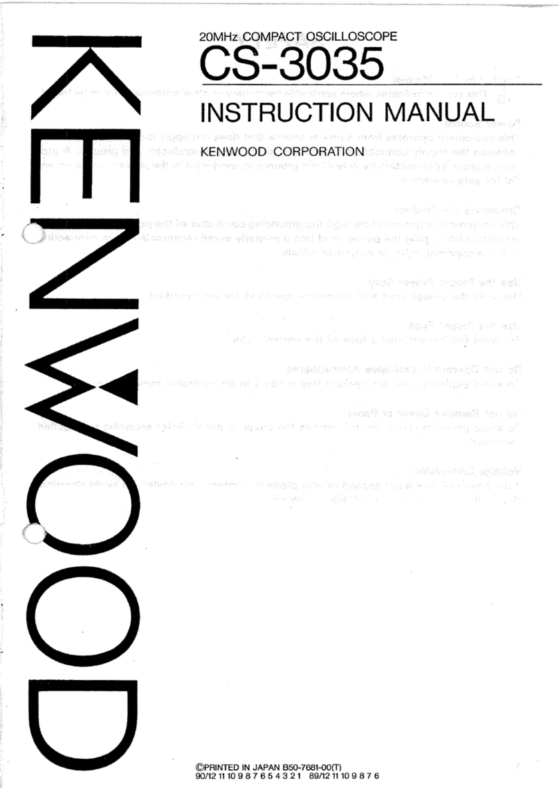
Kenwood CS-5230 User manual

40MHz
READOUT
OSCILLOSCOPE
CS-5230
40MHz
OSCILLOSCOPE
CS-5235
SERVICE
MANUAL
KENWOOD
CORPORATION
CH?
OSU
RP
OSa8
A
A
A
A
A
fA
fh
‘\
Vy
Vy
VA
|
:
WARNING
The
following
instructions
are
for
use
by
qualified
personnel
only.
To
avoid
electric
shock,
do
not
perform
any
servicing
other
than
contained
in
the
operating
instructions
unless
you
are
qualified
to
do
so.
CONTENTS
ADJUSTMENT.
.........cccccssscssscecsessseneasseussessusnesscseveusessasseeeassessesnseusessensevouseeneegenesenen
es
TROUBLESHOOTING.
...........ccccsccseesesneenene
PARTS
LIST
......cscescsccssrsssssescesrsenccssesssnsenasnes
DISASSEMBLY
.........ccccscsessessseeeseseneeeeeeeees
PARTS
LIST
(ELECTRICAL)
SCHEMATIC
DIAGRAM
...........cccesseeseeers
P.C.
BOARD
........seccssssssssccssetssesseseussenessensecsersensecsesnessseneuseessensesneeeseassnessesasnenseeateansnes
SEMICONDUCTORS
..........cccssscssssessssessescesesesenseseseraeseecesterssssaneosssesesaesesasnseetanaesanaees
SPECIFICATIONS
Type
150
mm
rectangular
tube
with
an
integral
graticule
Acceleration
voltage
Approx.
12
kV
Effective
area
8
X
10
divisions
(1
division
=
10
mm)
VERTICAL
AXIS
(COMMON
TO
CHANNELS
1
AND
2)
Sensitivity
(+10
to
+85°C)
;
1
mV,
2
mV/div
:
+5%,
5
mV
to
5
V/div:
43%
Attenuation
1-2-5
steps,
12
ranges,
fine
control
between
ranges
Input
impedance
1
MQ
+
2%,
approx.
25
pF
5mV
to
5V/div
DC
:
DC
to
40
MHz
AC
:
5Hz
to
40
MHz
DC:
DC
to
20MHz,
AC:
5Hz
to
20MHz
Frequency
response
(-3
dB)
(+10
to
+35°C)
Rise
time
(+10
to
+35°C)
Signal
delay
time
The
leading
edge
may
be
checked
using
a
square
wave
of
the
rise
time
less
than
that
of
this
model.
Crosstalk
-40
dB
or
less
(at
1
kHz)
A\Maximum
input
voltage
500
Vp-p
or
250
V
(DC+AC
peak,
1
kHz
or
less)
VERTICAL
AXIS
(CH3)
Sensitivity
(+10
to
+385°C)
0.1
V/div:
=3%
InV
to
2mV/div
5mV
to
5V/div
Approx.
8.8
ns
ImV
to
2mV/div
Approx.
17.5
ns
Input
impedance
IMQ
+
2%,
approx.
25
pF
Fre
c
sponse
(-3
dB
eroapency
rgsnayse
C8
a)
DC
to
40
Mii
Rise
time
(+10
to
+35°C)
Approx.
8.8
ns
Signal
delay
time
The
leading
edge
may
be
checked
using
a
square
wave
of
the
rise
time
less
than
that
of
this
model.
A\Maximum
input
voltage
100
Vp-p
or
50
V
(DC+AC
peak,
1
kHz
or
less)
Operat
ion
Single
trace:
CHl,
CH2,
CH3
or
ADD
single
trace
operation
Multi-trace
:
2
to
4
traces
of
CH1,
CH2,
CH3
and
ADD
ALT/CHOP:
Display
by
selecting
ALT
and
CHOP
ADD
:
Composite
waveform
of
CHI
and
CH2
signals
are
displayed.
SPECIFICATIONS
Chop
frequency
Approx.
250
kHz
(in
multi-trace
operation)
Channel
polarity
Normal
or
inverted,
CH2
only
inverted
Horizontal
axis
(CH2,
except
for
10
MAG
operation)
Sensitivity
(+10
to
+35°C)
Same
as
vertical
axis
(CH2)
Input
impedance
Same
as
vertical
axis
(CH2)
Prequency
respguse
€3
dB)
DC:
DC
to
1
MHz,
AC:
5
Hz
to
1
Miz
X-Y
phase
difference
1
3°
or
less
at
100
kHz
Operation
mode
X-Y
mode
is
selected
with
H.
MODE
CHI:
Y-axis,
CH2:
X-axis
AMaximum
input
voltage
Same
as
vertical
axis
(CH2)
SWEEP
Sweep
types
:
A
sweep
ALT
:
Alternate
A
sweep
and
B
sweep
B
:
B
sweep
X-Y
:
X-Y
oscilloscope
operation
Sweep
time
|
A
sweep
0.5s
to
0.1
us/div
(410
to
+85°C)
+3%
1-2-5
steps,
21
ranges,
fine
adjustment
between
ranges
B
sweep
ee
to
0.1
us/div
x
0
1-2-5
steps,
18
ranges,
fine
adjustment
betwen
ranges
meee
prado
er
aaa
x10
+
5%
(48%
for
over
0.5
ns/div)
Linearity
(+10
to
+35°C)
+3%
(5%
in
X10
MAG
operation)
HOLDOFF
Continuously
variable
from
A
sweep
NORM
position
Trace
Separation
B
sweep
is
continuously
variable
by
+4
divisions
or
more
with
respect
to
A
sweep.
Delayed
sweep
operation
Continuous
delay
operation
(AFTER
DELAY)
Synchronous
delay
operation
(B
TRG'D)
:
Synchronous
with
the
trigger
signal
Delay
time
Continuous
control
by
0.2
to
10
divisions
for 0.5
div
to
maximum
speed
sweep
[CS
-
5230]
:
+(3%
of
set
value+1%
of
full
scale)+(0
to
300
ns)
[CS
-
5235]
:
Reading
on
CRT
+4%
(0
to
300
ns)
Delay
time
error
(+10
to
+35°C)
Delay
jitter
10000
:
1
of
a
value
10
times
as
high
as
A
sweep
setting
SPECIFICATIONS
TRIGGERING
,
Trigger
modes
AUTO
:
Automatic
free
running
with
no
signal
NORM
:
Triggered
sweep
FIX
:
Sweep
at
triggering
point
set
to
center
of
signal
amplitude
SINGLE:
Single
sweep
mode
RESET
:
Restarting
single
sweep
operation
VERT:
Input
signal
selected
for
V.
mode
CH1
:
Channel
1
input
signal
CH2
:
Channel
2
input
signal
CH3
:
Channel
3
input
signal
:
Commercial
power
line
Trigger
signal
sources
AC
:
AC
coupling
from
10
Hz
HFrej
:
Low-pass
filter
coupling
up
to
30
kHz
DC
:
DC
coupling
TV
FRAME:
Composite
video
signal,
vertical
synchronization
separation
TV
LINE
:
Composite
video
signal,
horizontal
synchroni-
zation
separation
Trigger
coupling
(For
trigger
sensitivity,
see
the
table
below.
)
Trigger
sensitivity
(+10
to
+35°C)
Sensitivity
(Amp1itude)
10Hz
to
20MHz
Idiv
10Hz
to
30kHz
Idiv
DC
to
20MHz
Idiv
20M
to
40MHz
1.
5div
HDTV
HDTV
video
signal
AUTO
:
Same
as
above
specifications
for
above
40Hz.
(The
table
shows
the
sensitivities
in
terms
of
the
amplitude
displayed
on
the
CRT.
)
Qmin.
for
the
HFrej
sensitivity
shows
that
the
amplitude
necessary
for
synchroniza-
tion
increases.
)
COUPLING
Signal
frequency
FIX
*
:
Same
as
above
specifications
for
above
50Hz.
SPECIFICATIONS
CALIBRATION
SIGNAL
:
POSITIVE
SQUARE
WAVE,
1
Vp-p
23%,
APPROX. 1
kHz
100
Vp-p
or
50V
(DC+AC
peak)
Input
impedance
(+10
to
+385°C)
AMaximum
input
voltage
CHi
OUTPUT
SIGNAL
(WITH
50
Q
LOAD)
Output
voltage
Approx.
50
mVp-p/div
Frequency
100
Hz
to
20
MHz
response
(-3dB)
|
5
mV
to
100
Hz
to
40
MHz
TRACE
ROTATION
:
TRACE
ANGLE
1S
ADJUSTABLE
WITH
A
SEMI-FIXED
CONTROL
ON
PANEL.
POWER
SUPPLY
Voltage
100/120/220/230
VAC
+
10
%
50
Hz
or
60
Hz
Power
consumption
Approx.
43
W,
39
W
Approx.
52VA,
49VA
DIMENSIONS
AND
WEIGHT
(VALUES
ENCLOSED
IN
PARENTHESES
INCLUDE
PROJECTIONS.
)
300
mm
(300
mm)
150
mm
(172
mm)
400
mm
(469
mm)
Frequency
Aprrox.
8.7
kg
OPERATING
TEMPERATURE
AND
H
Operating
temperature
and
humidity
Storage
temperature
and
humidity
UM
|
DITY
0
to
40°C,
85%
RH
or
less
—20
to
70°C,
85%
RH
or
less
ACCESSORIES
Probe
PC-33
:
10
MQ
+1%,
22
pF+
10%,
10:
1
[CS-5230]
PC-35
:
10
MQ
1%,
19.5
pF+
10%,
10:
1
[CS-5235]
Instruction
manual
1
copy
Adjusting
screwdriver
a
Replacement
fuse
1
AX2
(for
100
V
area)
630
mAX2
(for
200
V
area)
SPECIFICATIONS
[The
specifications
shown
below
do
not
apply
to
the
CS-5235.]
READOUT
CH1
and CH2
scale
factors
(with
probe
detection),
CH3
scale
factor
(0.1
V/div
fixed,
with
no
probe
detection),
V-UNCAL,
ADD,
INV,
A/B
sweep
scale
factors
(MAG-converted),
sweep
-
UNCAL,
DELAY
TIME,
TRIG’D,
X-Y
Set
values
AV1
:Displayed
in
voltage
with
conversion
according
to
CH1
scale
factor
Cursor
modes
(Between
AREF
and
A
cursors)
AV2
:Displayed
in
voltage
with
conversion
according
to
In
X-Y
mode,
only
AVI]
CH2
scale
factor
may
be
set.
AV3
:Displayed
in
voltage
with
conversion
according
to
CH3
0.1
V/div
AT
:Displayed
in
time
with
conversion
according
to
A
sweep
scale
factor
1/AT:Displayed
in
frequency
with
conversion
according
to
A
sweep
scale
factor
In
V,
H-VARI
or
RATIO:Voltage
ratio
and
time
ratio
are
displayed,
UNCAL
mode
with
5
divisions
on
the
CRT
as
100%.
PHASE:Phase
difference
is
displayed,
with
5
divisions
on
the
CRT
as
360°
.
Resolution
:
10
bits
Measuring
error:
+4%
Measuring
range:
+3.6
divisions
or
more
vertically
from
CRT
center.
+4,.6
divisions
or
more
horizontally
from
CRT
center.
Cursor
measurement
WiThe
specifications
shown above
are
subject
to
change
without
notice.
SAFETY
SAFETY
Before
connecting
the
instrument
to
a
power
source,
care-
fully
read
the
following
information,
then
verify
that
the
proper
power
cord
is
used
and
the
proper
line
fuse
is
installed
for
power
source.
The
specified
voltage
is
shown
at
the
fuse
holder
of
the
AC
inlet.
If
the
power
cord
is
not
applied
for
specified
voltage,
there
is
always
a
certain
amount
of’danger
from
electric
shock.
Line
voltage
This
instrument
operates
using
ac-power
input
voltages
that
100/120/220/230
V
at
frequencies
from
50
Hz
to
60
Hz.
Power
cord
The
ground
wire
of
the
3-wire
ac
power
plug
places
the
chassis
and
housing
of
the
oscilloscope
at
earth
ground.
Do
not
attempt
to
defeat
the
ground
wire
connection
or
float
the
oscilloscope;
to
do
so
may
pose
a
great
safety
hazard.
The
appropriate
power
cord
is
supplied
by
an
option
that
is
specified
when
the
instrument
is
ordered.
The
optional
power
cords
are
shown
as
follows
in
Fig.
1.
Plug
configuration
Power
cord
and
plug
type
North
American
120
volt/60
Hz
Rated
15
amp
(12
amp
max;
NEC)
Universal
Europe
220
volt/50
Hz
Rated
16
amp
Line
fuse
The
fuse
holder
is
located
on
the
rear
panel
and
contains
the
line
fuse.
Verify
that
the
proper
fuse
is
installed
by
replacing
the
line
fuse.
Voltage
conversion
This
oscilloscope
may
be
operated
from
either
a
100
V
to
230
V,
50/60
Hz
power
source.
Use
the
following
procedure
to
change
from
100
to
230
volt
operation
or
vice
versa.
1.
Remove
the
fuse
holder.
2.
Replace
fuse
F
1
with
a
fuse
of
appropriate
value,
1
amp
for
100
VAC
to
120
VAC
operation.
630
m
amp
for
220
VAC
to
230
VAC
operation.
3.
Reinsert
it
for
appropriate
voltage
range.
4.
When
performing
the
reinsertion
of
fuse
holder
for
the
voltage
conversion,
the
appropriate
power
cord
should
be
used.
(See
Fig.1.)
Factory
installed
Line
cord
instrument
fuse
plug
fuse
Parts
No.
for
power
cord
1A,
250
V
Fast
blow
E30-1951-05
6
x
30
mm
North
Europe
630
mA,
250
V
Slow
blow
5
x
20
mm,
E30-1952-05
Other
Europe
630
mA,
250
V
Slow
blow
6
x
30
mm
U.K.
240
voit/50
Hz
Rated
13
amp
630
mA,
250
V
Slow
blow
E30-1947-05
6x
30
mm
Australian
240
volt/50
Hz
Rated
10
amp
630
mA,
250
V
Slow
blow
E30-1821-15
6
x
30
mm
North
American
240
volt/60
Hz
Rated
15
amp
(12
amp
max;
NEC)
630
mA,
250
V
Slow
blow
6x
30mm
Switzerland
240
volt/50
Hz
Rated
10
amp
630
mA,
250
V
Slow
blow
6x30
mm
Fig.
1
Power
Input
Voltage
Configuration
CIRCUIT
DESCRIPTION
VERTICAL
PREAMPLIFIER
UNIT
CH1,
CH2
Each
of
the
CH1
and
CH2
inputs
passes
through
an
AC/DC/GND
switch
and
enters
the
1st
attenuator
(1/1,
1/10,
1/100).
The
1stattenuator
is
used
in
combination
with
the
2nd
attenuator
(1/1,
1/2,
1/4,
1/10)
and
the
5-fold
function
of
the
2nd
amplifier,
to
switch
the
12
vertical
ranges.
The
head
amp
is
composed
of
Q102
and
U101
(Q202
and
U201)
and
isa
1/1
buffer
amp
with
an
input
impedance
of
1
megohms
and
used
for
conversion
of
impedance.
Q102
(Q202)
is
the
source-follower.
This
head
amp
is
installed
between
the
1st
and
2nd
attenuators.
Starting
from
the
2nd
amp,
this
unit
takes
the
differential
amplifier
configuration.
The
functions
of
U102
(U202)
include
the
variation
and
inversion
functions.
The
variation
function
allows
to
vary
the
gain
continuously
according
to
the
voltage
applied
to
pin
5.
The
inversion
function
allows
to
invert
the
phase
according
to
thevoltages
applied
to
pins
6
and
7.
As
this
function
is
provided
only
for
CH2,
CH1
is
fixed.
At
the
CH2
side,
switch
is
done
by
Q215.Q103
(0203)
is
the
regulated
current
supply
for
U102
(U202).
Q106
and
Q107
(Q206
and
Q207)
form
an
emitter-grounded
amp.
Q108
to
Q111
(Q208
to
Q211)
form
the
cascode
amp
of
the
differential
amp.
The
vertical
position
can
be
moved
by
regulating
the
current
applied
to
the
emitter
of
Q111
(Q211)
based
on
the
panel
operation.
CH3
With
CH3,
the
attenuator
is
fixed.
The
signal
impedance
is
converted
by
the
buffer
amp
of
source
follower
Q303
and
regulated
current
supply
Q304
and
the
signal
is
sent
to
emitter-
follower
Q305.
Q305
is
the
signal
side
input
stage
of
the
differential
amp.
Emitter-follower
306
is
the
input
stage
of
a
constant-potential
differential
amp.
The
outputs
from
Q305
and
Q306
are
input
to
the
differential
type
cascode
amp
formed
by
0307,
0308,
0310
and
Q311.
The
current
of
the
cascode
amp
is
determined
by
regulated
current
supply
Q309.
The
vertical
position
can
be
moved
by
regulating
the
current
applied
to
the
emitter
of
Q311
based
on
the
panel
operation.
Channel
selector,
delay
line
drive
‘As
for
the
outputs
from
the
position
amps
of
the
channels,
only
the
signal
of
thechannel
with
which
the
cathodes
of
CH1
-D104,
D105,
CH2
-
D204,
D205,
CH3
-
D301,
D302,
D304,
D305
are
turned
“H”
by
the
signals
from
V-MODE
LOGIC
is
sent
through
CH1
-
D103,
D106,
CH2
-
D203,
D206,
CH3
-
D303,
D306
and
transmitted
to
the
delay
line
driver.
Q2
and
Q3
form
a
feedback
amp.
Q1
lets
the
excessive
bias
current
flow
when
CH1
or
CH2
is
in
ADD
mode.
Trigger
amp,
trigger
selector
With
CH1
(CH2),the
differential
outputs
from
U102
(U202)
are
input
to
the
emitter-followers
Q152
and
Q153
(0252
and
0253),
where
Q153
(Q253)
forms
a
cascode
amp
with
0114
(Q214).
With
CH3,
the
signal
after
the
buffer
amp
is
sent
through
the
buffer
of
emitter-follower
0314,
feedback
amp
Q312
an
output
as
current
from
the
collector
of
emitter-follower
0313.
Only
the
signal
of
the
channel
with
which
the
cathode
of
CH1
-
D108,
CH2
-
D208,
CH3
-
D308
is
turned
“H”
by
the
signal
from
the
trigger
controller
is
sent
through
CH1
-
D107,
CH2
-
D207,
CH3-
D307
and
output
as
current
to
the
Horizontal
unit.
Q31
the
excessive
bias
current
flow
when
CH1
or
CH2
is
in
ADD
mode.
CH1
OUT
The
CH1
outputis
sent
from
the
collector
of
Q152,
through
emitter-
follower
Q51
and
output
at
CH1
OUT
of
the
Final
unit.
Trigger
controller
The
data
on
the
trigger
source
set
on
the
panel
is
input
to
pin
1
of
U1
and ”H”
or
“L"
is
output
at
pins
4
to
8
according
to
the
set
state.
U2
is
used
to
switch
between
the
data
from
U1
and
the
CRT
display
data
of
each
channel
from
V-MODE
LOGIC.
If
the
current
mode
is
not
V
mode,
the
former
data
is
selected.
If
the
current
mode
is
V
mode,
the
latter
data
is
selected
for
use
in
controlling
the
trigger
selector.
Among
CH1
-
U2
pin
7,
CH2
-
U2
pin
9,
CH3
-
U2
pin
12,
the
terminal
set
with
the
panel
is
turned
“H”".
V-MODE
LOGIC
U3
and
U4
generates
a
signal
synchronized
with
the
display
channel
select
signal
from
the
panel
and
the
end
of
horizontal
sweep,
anda
signal
for
controlling
the
channel
selector
based
on
the
CHOP
signal.
(Figure
1)
Q34
cuts
off
the
power
supply
to
U4
only
at
the
instant
the
channel
switch
is
pressed,
in
order
to
prevent
malfunction.
Vertical
range
converter
U401,
U403,
$102
and
$202
output
the
vertical
range,
CAL
and
UNCAL
data
by
turning
them
into
analog
values
using
an
opamp
for
use
as
the
R/O
data.
(Figures
3,
4)
Horizontal
range
converter
U402
and
$401
output
the
horizontal
range
data
using
an
opamp,
as
analog
values
for
R/O
data.
(Figure
5)
U404
(for
main
sweep),
U405
(for
sub-sweep)
and
S401
are
used
to
switch
the
reference
voltage
for
letting
the
sweep
current
of
the
1-2-5
steps
of
horizontal
sweep
flow.
(Figure
2)
FINAL
UNIT
Final
amplifier
The
signal
sent
from
the
vertical
preamp
through
the
delay
line
is
input
to
the
feedback
amp
of
Q1
and
Q2.
During
A
ALT
B
sweep,
the
variation
of
the
vertical
position
of
sweep
B
is
controlled
by
the
current
applied
to
the
base
of
Q2
based
on
the
panel
operation.
Q3,
4,
Q105,
Q106
and
U1
are
used
to
amplify
the
vertical
signal
|
10
CIRCUIT
DESCRIPTION
and
U1,
Q105
and
0106
are
used
to
amplify
the
R/O
characters.
U1
is
used
to
switch
between
the
vertical
signal
and
R/O
signal.
Q9-012,
0113
and
Q114
are
cascode-connected
for
use
in
driving
the
CRT.
AC
inlet,
fuse
An
external
commercial
supply
voltage
switch
and
fuse
holder
are
provided.
Line
filter
A
filter
for
elimination
of
common
mode
noise
and
normal
mode
noise
is
provided.
CH1
OUT
The
signalfrom
the
vertical
preamp
is
output
externally
via
Q201
and
Q202
as
a
signal
with
50-ohm
impedance.
HORIZONTAL
UNIT
Trigger
The
trigger
signal
supplied
from
the
Vertical
unit
(X73-2070)
is
AC/DC
coupled
and
the
trigger
level
is
added
to
it.
The
obtained
signal
is
inout
to
the
trigger
shaping
circuit
to
become
a
pulse
signal.
If
FIX
is
selected,
the
trigger
level
is
fixed
so
that
it
is
always
around
the
center
of
the
waveform.
With
TV-V,
the
composite
video
signal
is
separated
by
the
V
sync
separator
and
input
to
the
trigger
shaping
circuit.
With
TV-H,
the
composite
video
signal
is
separated
by
the
H
sync
separator
and
input
to
the
trigger
shaping
circuit.
HFrej
is
used
to
apply
a
50
kHz
LPF
to
the
trigger
signal.
The
polarity
of
the
trigger
pulse
signal
can
be
changed
with
SLOPE
+/-.
The
output
signal
is
input
to
the
sweep
logic
circuit.
There
is
an
additional
circuit
which
applies
the
trigger
signal
to
the
sweep
logic
in
case
the
trigger
pulse
signal
has
not
been
input
for
a
certain
period
and
auto
free-run
mode
has
been
selected.
Sweep
When
the
trigger
pulse
is
input
to
the
sweep
logic,
the
sweep
gate
is
activated
and
the
sweep
wave
is
output.
When
the
sweep
wave
reaches
a
certain
level,
the
sweep
stop
circuit
is
activated
to
close
the
sweep
gate
and
end
sweep.
When
sweep
stop
is
activated,
the
hold-off
circuit
is
activated
and,
in
a
certain
period
after
it,
the
sweep
logic
enters
the
trigger
standby
state.
The
delayed
sweep
is
performed
either
as
the
AFTER
DELAY
sweep
or
B
TRIG’D
sweep.
With
the
AFTER
DELAY
sweep,
the
voltage
level
of
the
main
sweep
wave
and
the
voltage
set
with
DTP
are
compared
and
delayed
sweep
is
performed
using
the
result
signal
as
the
trigger.
With
the
B
TRIG'D
sweep.
sweep
is
triggered
by
the
next
trigger
signal
input
after
the
voltage
level
of
sweep
wave
have
reached
the
voltage
set
with
DTP.
In
case
ALT
sweep
is
set,
the
main
sweep
and
delayed
sweep
are
performed
alternately.
Horizontal
amp
This
circuitry
switches
between
the
sweep
wave
generated
in
the
sweep
block
and
the
X
signal
and
add
H-POSITION.
After
being
magnified
by
10
times
if
MAG
has
been
selected,
the
signal
is
input
to
the
R/O
switch.
Here,
the
R/O
signal
is
added
to
the
vertical
signal
and
the
signal
is
amplified
by
the
final
amp
to
a
high
enough
voltage
level
to
drive
the
CRT.
Intensity
circuit
The
Z
signal
is
generated
with
the
sweep
gate
of
the
main
sweep
and
that
of
the
delayed
sweep.
During
ALT
sweep,
a
waveform
for
increasing
the
intensity
of
the
delayed
sweep
section
is
generated
with
the
main
sweep.
The
voltage
set
with
the
INTEN
potentiometer
is
added
to
the
X
signal
and
the
voltage
set
with
the
R/O
INTEN
potentiometer
is
added
to
the
R/O
blanking
signal
and
they
are
input
to
the
high
voltage
circuit.
The
high
voltage
circuits
generates
the
CRT
cathode
voltage,
G1
voltage
and
P1
voltage
based
on
the
intensity
signal
and
the
FOCUS
potentiometer.
The
cathode
voltage
is
controlled
always
constant
by
the
opamp.
For
use
with
the
after-accelerating
CRT,
the
anode
voltage
is
also
generated
by
the
high
voltage
circuit.
Power
supply
AC
voltages
of
+14.8
V,
-14.8
V,
+6
V,
-6
V,
+67
V
and
+170
V
are
input
from
the
transformer,
and
they
are
turned
into
stable
DC
voltages
of
respectively
+12
V,-12
V,
+5
V,
+55
Vand
+140
V,
which
are
supplied
to
their
respective
units.
CHOP
To
observe
signals
of
multiple
channels
simultaneously,
the
vertical
amp
is
switched
with
the
CHOP
signal.
PANEL
UNIT
This
unit
sends
the
potentiometer
and
switch
data
from
the
control
panel
to
other
units.
A
limiting
circuit
is
provided
to
prevent
the
CHIP
operation
while
multi-channel
operation
is
not
selected
even
when
the
CHOP
key
Is
pressed.
The
voltage
setting
of
DTP
is
made
by
the
opamp
in
the
range
from
0
to
+4
V.
The
CAL
signal
is
a
1
kHz,
1
Vp-p
square
wave.
The
intensity
is
controlled
by
the
PWM
based
on
the
output
from
the
original
oscillator
of
CAL.
R/O
UNIT
The
R/O
unit
(X77-1870-00)
accepts
the
attenuator
and
sweep
data
sent
from
or
through
the
Panel
unit
and
outputs
character
data
to
be
displayed
on
the
CRT.
It
is
composed
of
the
controller
block
(U1,
U2,
U4
U6,
X1),
blanking
circuit
(U5,
U14,
U15,
X2),
A/D
converter
block
(U3,
U16,
U17)
and
character
data
output
block
(U7,
U8
U9,
U10,
U13).
The
controller
block
is
composed
of
the
1-chip
CPU
(with
built-
in
ROM),
RAM,
decoder,
ALE
and
oscillator
x
1.
The
1-chip
CPU
CIRCUIT
DESCRIPTION
(U1)
incorporates
a
ROM
as
descried
above,
and
the
entire
unit
is
controlled
by
the
software
written
in
this
ROM.
The
1-chip
CPU
is
operated
based
on
X1
(10
MHz).
Before
the
start
of
operation,
the
reset
signal
is
input
from
U18
when
the
power
is
switched
on.
The
1-chip
CPU
incorporates
8-bit
A/D
converters
in
the
output
ports,
input
ports
and
also
internally,
and
it
outputs
character
data
for
CRT
display
based
on
the
data
input
through
“the
A/D
converters.
As
for
the
output
port
configuration,
P40
to
P47
and
P30
to
P33
in
the
circuit
diagram
output
comparison
data
for
an
external
12-
“bit
A/D
converter
and
P34
to
P37
output
the
control
data
for
use
,
in
switching
the
analog
data
to
the
external
12-bit
A/D
converter.
As
for
the
input
port
configuration,
P60
to
P64
are
used
to
recognize
the
“H”
or
“L"
level
of
the
push
switches
on
the
panel
and
input
the
CURSOR
MODE,
B
TRIG'D,
CH2
INV
and
X10
MAG
signals.
Among
them,
the
CURSOR
MODE
switch
is
a
non-locking
switch
so
a
Schmitt
circuit
is
provided
before
the
signal
is
input
to
the
port.
P50
to
P57
are
the
analog
voltage
input
ports.
The
inputvoltage
is
sent
to
the
internal
8-bit
A/D
converter,
converted
into
digital
data
and
becomes
the
CRT
display
data.
The
1-chip
CPU
has
a
bus
configuration
of
8
data
bus
bits
and
16
address
bus
bits.
A
the
lower
8
bits
of
the
address
bus
are
also
used
as
the
data
bus
bits,
IC
(ALE
circuit
|C)
U6
is
provided
for
their
separation.
In
addition
to
above,
the
controller
block
also
incudes
a
decoder
(U4)
and
memory
(U2).
The
decoder
output
is
supplied
to
the
memory
as
Wellas
to
the
X
latch
CLK
input,
Y
latch
CLK
inputand
blanking
circuitblock
which
will
be
described
below.
The
memory
functions
as-the
system
RAM
of
the
1-chip
CPU
and
also
stored
CRT
display
data.
The
stored
data
is
some
of
the
data
which
has
originally
been
prepared
in
the
ROM
inside
the
1-chip
CPU;
only
the
data
required
for
CRT
display
is
stored
in
this
memory.
Next,
the
blanking
circuit
block
is
composed
of
a4
MHz
oscillator
composed
of
X2
and
the
inverter
(U15),
shift
register
(U14),
inverter
(U15)
and
OR
(U5).
It
outputs
the
Blanking
(R/O
BLK),
request
(R/O
REQ)
and
unblanking
(R/O
UBL)
signals.
The
signals
are
output
at
the
timing
synchronized
with
the
CLK
signal
from
the
decoder
to
X
latch
(U7)
and
Y
latch
(U8)
and
used
to
switch
the
display
from
waveform
to
character
or
from
character
to
waveform
and
to
clear
the
trace
during
switching.
R/O
BLKis
used
to
clear
the
trace,
R/O
REQ
is
used
to
switch
display
between
characters
and
traces
and
R/O
UBL
is
used
to
illuminate
a
single
dot
inthe
character.
In
synchronism
with
the
signal
outputs
from
the
blanking
circuit
block,
the
character
data
output
block
outputs
R/O-X
(character
dot
position
in
Horizontal
direction)
and
R/O-Y
(character
dot
position
in
Vertical
direction).
The
character
data
is
sent
from
the
memory
(U2)
described
above
to
the
X
latch
and
Y
latch,
and
the
position
data
is
sent
through
the
address
bus.
These
data
arelatched
simultaneously,
and
the
latched
data
are
input
to
the
respective
8-bit
D/A
converters
(U9,
U10)
to
be
converted
into
analog
signals.
After
conversion,
the
obtained
analog
signalsare
input
to
analog
switches
U11
and
U12,
output
from
opamp
U13
as
signals
with
0
to
4
V
amplitudes,
and
sent
respectively
to
the
final
amp.
The
analog
switches
are
supplied
with
the
cursor
voltages,
which
are
used
to
determine
the
CRT
screen
position
in
case
the
cursor
output
is
required.
The
relationship
between
these
voltages
and
the
CRT
screen
display
is
as
shown
in
the
following
diagram.
OV
4V
4V~-—_—————-
0V
In
addition,
there
is
an
external
12-bit
A/D
converter
for
use
as
the
means
to
input
character
data.
This
converts
the
cursor
voltages
,
sweep
time
voltage,
DTP
voltage,
etc.,
which
require
acertain
resolution
into
digital
data.
The
A/D
converter
is
formed
with
an
analog
switch
(U17),
comparator
(U3)
and
D/A
converter
(U16)
for
A/D
conversion
with
the
successive
comparison
method.
11
12
CIRCUIT
DESCRIPTION
V-MODE
LOGIC
When
CH1
is
selected
with
V-MODE
P12-9
CHi
L
P12-8
CH2
H
P12-7
CH3
H
P12-6
ADD
H
P9-5
V.CLK
T
T T
T
U3-6
CIE
T
es
ae
U3-9
Cop?
teh)
de
U3-5
Cle:
2
ee
U3-7
C2E
I
Q310-C
cH3
4
—W—_1___1.___1
Q311-C
(CTE
AND
C2E)
When
CH2
is
selected
with
V-MODE
P12-9
P12-8
P12-7
P12-6
P9-5
U3-6
U3-9
U3-5
U3-7
Q310-C
Q311-C
CHI
CH2
CH3
ADD
V.CLK
C1E
C2E
CiE
C2E
CH3
(CIE
AND
C2E)
When
CH3
is
selected
with
V-MODE
P12-9
P12-8
P12-7
P12-6
P9-5
U3-6
U3-9
U3-5
U3-7
Q310-C
Q311-C
CHI
H
CH2
H
CH3
L
ADD
H
Vp
ea
CE
eee
ard
ee
L
cieE
7
I
ES
ae
a
(CTE
AND
C2E)
Fig.
1-a
Fig.
1-b
Fig.
1-c
CIRCUIT
DESCRIPTION
When
ADD
is
selected
with
V-MODE
P12-9
CHi
H
P12-8
CH2
H
P12-7
CH3
H
P12-6
ADD
L
P9-5
ViCLK
“=
Sk).
U3-6
ce
TT
U3-9
C2E
Te
oe
ke
U3-5
CTE
25
U3-7
Cie
2h
Q310-C
CH3
——l
Q311-C
(CIE
AND
C2E)
Fig.
1-d
There
are
16
combinations
obtained
from
the
4
states,
and
it
is
abnormal
if
all
of
these
are
“H”.
When
more
than
one
combination
are
used,
the
state
is
switched
at
the
negative
going
of
V.CLK
in
the
order
shown
below:
[|
asweep
|
sweep
|.
TAGE
RANGE
(Vv)
|
VOLTAGE
(Vv)
|
VOLTAGE
(V)
Cc
S|
.
Ae
ee
ge
Approx.
-7.6
Pol
se"
re
|
0.168
~
0.301
Approx.
-6.9
tO
ot
Ee
Te
PT
poms
|
|
[O|
|
|
|
[ol
|
|
0505-0704
|
fol
[fot
Tol
|
—ars-ca
—]
|
|
fofol
|
{|
fofol
|
[
o839~1.044
|
FELL
Te
1088-207
S[
pol
tert
tol
[2-161]
|
|
fof
fol
|
1382-1584
|
|
fofot
|
|
Jofot
|
15e5~1784
|
fo]
[ofo]
{ol
Jofot
|
1785-1918
|
|
[ofofo[
|
[fofofol
|
1919~2124
emp
ee
ef
eat
allt
2.12
~
2.327
a
ae
a
ed es
ae
2.328
~
2.461
Ce
Soe
Col
eT
|
fof
[ol
|
Jo] [o]
2665-2864
|
St
fol
polar
[ol
[ot
2ass
286.
|
foto;
fof
[ofo]
Jo]
2909-3204
|
au
|
[olol-|
|
lolol
sz
sao
rot
Tojotol
|
fotot
swear]
|
aus
|
[S|
Tool
lo]
lolo]
sse-s7
oous
|
|
[ofofo]
|
[ofolo]
—
>373
|
Approx.76
|
P10-6,
1
|
cneck
pons
-
“8207099
_}_ta
Fig.
2
13
CIRCUIT
DESCRIPTION
@
CH1
ATT
&
CH2
ATT
voltage
check
table
V-Range
(
/div)
Voltage
range
(V)
5V
4.124
~
4.450
2V
3.790
~
4.123
1V
3.456
~
3.789
0.5V
3.130
~
3.455
2.804
~
3.129
2.470
~
2.803
50mV
2.136
~
2.469
1.484
~
1.809
5mV
1.150
~
1.483
2mvV
0.816
~
1.149
0.490
~
0.815
Fig.
3
CH1
CHECK
POINT
P23-4
CH2
CHECK
POINT
P23-6
@
UNCAL
voltage
check
table
CH1
CAL
|
CH2
CAL
|
SWP
CAL
Voltage
range
(V)
> >
4.406
~
4.860
>
CAL
3.777
~
4.405
th
|
CAL
0.626
~
1.256
CAL
0.156
~
0.625
Fig.
4
CHECK
POINT
P23-15
@
SWEEP
CODE
voltage
check
table
SWEEP
TIME
(
/div)
Voltage
range
(V)
3.542
~
3.743
3.408
~
3.541
3.205
~
3.407
2.999
~
3.204
2.865
~
2.998
5us
2.665
~
2.864
2.462
~
2.664
2.328
~
2.461
2.125
~
2.327
1.919
~
2.124
1.585
~
1.784
1.382
~
1.585
5ms
1.045
~
1.247
2oms
ee
Fig.
5
CHECK
POINT
ASWEEP
P23-11
B
SWEEP
P23-13
50s
@
V-MODE
level
check
table
OFF
ON
OFF
ON
OFF
ON
OFF
OFF
OFF
ON ON
_
OFF
OFF
OFF OFF
OFF
OFF
ON
ON
t
L
JL
oO
22
CH1+CH2
|-—
-
F-
LIK:
CH2
Je
rm
xr
rie
CH1+CH2
|o
oe
r|-
PSs
CH1
(CH3)*
CH14+CH2
|<
Dez
CH1+CH2
|
Ir
re
CH1 CH1
*
CH3
display
is
used
when
only
CH3
is
ON.
Fig.
6
CHECK
POINT
P23-4
P23-10
P24-6
@
MAG
level
check
CHECK
POINT
P23-17
Fig.
7
‘le
i
@
CH2
INV
level
check
table
CHECK
POINT
P23-12
Fig.
8
L
e@
B
TRIG’
level
check
table
CHECK
POINT
P23-19
H
Fig.
9
L
H
DISPLAY
voltage
check
table
ALT
XY
CHECK
POINT
P23-20
Fig.
10
e
Probe
voltage
check
table
|
|
Output
voltage
range
(V)
CHECK
POINT
>
CH1PB
:
P23-3
eae
CH2PB
:
P23-5
1/10
3.176
~
4.196
1/100
$
3.175
Fig.
11
e
CURSOR
voltage
check
table
rf
a
Fig.
12
wa
tet
ATT
a
CH2
INPUT
©
CH3
INPUT
@
ATT
CS-5230
BLOCK
DIAGRAM
a
X73-2070-00
VERTICAL
UNIT
Amp
1
1
!
!
t
1
1
_
H
X80-1370-00
A/4
'
I
Va
4st
ATT
al
HEAD
Aup
2nd
ATT
and
Amp
POSI
Amp
CHANNEL
DELAY
LINE
R/O
SW
CH4
INPUT
@
1/4,
172
a103.
4
bioncres
SELECTOR
T.SEP
Amp
1/4.
4740
,
£02
.
406
DRIVER
U4,
G3,
4
parte
1/4,
1740
@107,
U102
L___3}
0103~106
ai.2
ao~12
17100
n20ass08
@i~-3.
D2
@105,
106
aii3.
444
D301~306
TRIG
Amp
FINAL
UNIT
aii4
as
Sores)
SAPS
eTer
sea
a
as
die
(peered
(Cee
SSS
eto
a
ores
peser
ass
ness
@i52, 153
V-MODE
POSI
Amp
a208~214
foSssss2sssSeeSS-S<=5
'
Y-LATCH
us
|
:
X-LATCH
as
—
nix
Multiplex
I|_,|
DECORDER
V
FINAL
ai107.
108
i
2nd
ATT
1/4.
172
1/4,
1740
POSI
Amp
4
fe
a305~314
3
2nd
Amp
@203,
206
@207,
U202
@2i6
4174,
4740
47100
mew
ewe
ewe
eee
eee
TRIG
Amp
@3i2.
313
Vv
RENGE
H
RENGE
BLK
CONVERTER
CONVERTER
CIRCUIT
u4o4
U402~405
u17
US,
14,
15
4MHz
GEN
x2,
U15
i
TRIG
Amp
~
X-Amp
i
CReenUN
a154.
152
@304.
302
Siocae
te.
eC
IO
AP
bee
ee
ee
os)
Se
|
SSSR
BREST
eR nS
setee
cera
sce
.
D301~303
pasecis
|
ed
be
ON
A
LOSE
See
e
sess
e
sees
tessa
sess
esces
assesses
al
TRETACUIT
A
SWEEP
‘A
SWEEP
:
TRIG
Coup
cracu
E
uio2
@i04
X
SELECTOR
eer
@2e.
158
6AT
i
;
U3.
016,
17
G3.
4,
21
Q5~7,
47,
18
|
U48
$4,508
iT
VIDEO
Amp
i
-—
|
pio,
ai
43
HOLDOFF
U304,
@303
D345,
346
;
A
SWEEP
STOP
D1i04~406
U103,
@102
rie
|
Ln
HIGH
VOLTS
u204,
W204
LYvieee
AAO
mGhiE.
bane
<
1
—
—
a2i2.
243
1X66—-1400-00
PANEL
UNIT
B
SWEEP
8
SWEEP
rere
Be
us847
fos
Qizs-128
oe
AUTO
FOCUS
D133,
a106
Gt23~4
|
adders
ENTENGVA
A/0
INTEN
B
SWEEP
DTP
i
STOP
cIACUIT
Ui103.
a106
Q@409,
110
@103~108
,
1
au
1
t
=e
‘
1
t
CHOP
GEN BLK
LOGIC
@Q113~446
:
ai47~449
a
D109~448
ie
|
1
1
a=
t
1
1
!
X74-1580-00
HORIZONTAL
UNIT
BLK
Amp
Q201~207
D204,
202
1
'
VOLTAGE
H
aNTEN
REGULATOR
t
ROTATION
re
vied
D207~240
GIRCUTT,
on
@103,
104
as04,
102
D104,
102
u4os
tn
t
1
@401~407
D401~409
X80-1370-00
D/4!
'
1
FILTER
AC
INLET
C
|
1
'
t
FINAL
UNIT
POWER
TRANSFORMER
poco
ctor
ee ee
eee
ee
X80-1370
-00
C/4
FINAL
UNIT
X80-1370
-0Q0
D/
4
CH1OUT
Amp
a2014,
202
15
16
CHi1
INPUT
CH2
INPUT
CH3
INPUT
CS-5235
BLOCK
DIAGRAM
pte
nn
en
nn
nnn
en
nn
nnn
nn
nn
nn
enn
nn
nnn
nnn
nnn
nn
nn
nnn
enn
nnn
eerie
Seuss
edi
ee
eecwus
=
pone
n
n-ne
enn
4
1
1
i
H
t
i
1
CHAOUT
H
1X80-41370
1
i
X73-2070-01
VERTICAL
UNIT
‘
‘
!
‘
Lo
pee
em
mmm
m
ewe
m
men
pew
w
nee
e
ewe mew
wee
m
ew
n
wen
e
cece
nnce
t
-O1
C/4
'
1
1 1
1
.
1
FINAL
—
t
St
O41:
|
7
FN
1
UNIT
!
ist
ATT
HEAD
Amp
2nd
ATT 2nd
Amp
DELAY
LINE|
jj
T.SEP
A
as,"ENMo
t 1
@
474.
1740
@404,
102
41/4,
472
@4103.
106
DRIVER
:
mp
ao~s2
i
4
47400
UsL04
474.
4710
@107.
U102
a
ansoe
Qi~3.
D2
1
ai.
2
ores
706
!
'
<
:
7
:
D301~306
t
!
1
'
1
‘
TRIG
Amp
!
' !
1
ml
i
Guied-
Swedes
wowwocece
dl
Shnmesaae
woo
eaad
Hele
ac
ee
cece
ce
aes
J
1
aiid
ewww
ed
ewe
ww
ww
we
we
ew
ww
wwe
EO
OO
me
ewww
em wm
ew
em em ew
ewe
errr
wr
errerrrrnrnrererees
;
@152,
183
'
ish
u
| |
fe
1 {
1
i]
ist
ATT
2nd
ATT 2nd
Amp
|
HEAD
Am
1
@
1/4,
1740
azot.
208
1/4,
1/2
a203.
206
'
1
17100
u204
1/4.
4710
@207,
U202
1!
'
aoe
fm
Gg
re
1
‘
1
t
1
f ' {
!
teehee
debe
1
=)
‘
i
HERD
Aap
POSI
A
CONTROLLER
.
@302~306
Q305~344
U1.
2
4
t
1
i]
'
i
TRIG
:
sELECT
OS
4
@34.
035
:
H
RENGE
D407.
108
1
CONVERTER
D207,
208
U404,
405
D307,
308
'
ee
(i
ener
cece
et
DE
ome
ee
oes
eer
eee
oR
MAG
Qi0.
|
peleciososcuecbennaersseveseess
|
:
7
A
SWEEP
A
SWEEP
CIRCUIT
GATE
u4o2,
a104
x
SELECT!
ere
guaavaea
“abi
I
U3.
D416,
17
|
j
es
0312
EEP
Q5~7,
47,
48
Q26,
156
H
MODE
ae
!
utoytfoo
P|
e
SMEEP
>a
us84.
fos
UL05.
@407
D433,
2406
ie
@123~425
ge
‘
ae
1
CHOP
GEN
BLK
LOGIC
aiis~116
@is7~419
Di09~4418
re
s
awEee
*
STOP
CIRCUIT
u403.
a106
1
t
t
1
'
ae
X74-1580-01
HORIZONTAL
UNIT
Pp
a3z01.
302
D301~303
A
SWEEP
STOP
3,@
a
Reon
HIGH
VOLTS
Conv
u2o1.
W204
@242.
243
021141~243
ES
ae
et
ew
ee
ee
eee
mee
ne
on
Ie
eg
ee,
oo
|
X66-1400-01
;
—
B/2
PANEL
UNIT
1
leecase
:
REGULATOR
0207~210
CIRCUIT
A
Udod
'
@401~407
t
D401~409
:
t
BLK
Amp
@204~207
D204.
202
@4109.
110
r
!
|
1
H
H
'
POWER
1
TRANSFORMER|
1
AC
INLET
C
|
t
'
H
H
'
1
a303~
U304,
@303
rtp
aee4
D315,
346
—O
D/4
CH10OUT
Amp
@a204,
202
SY
Be
ee
ee
we
we
re
es
we
ADJUSTMENT
To
obtain
the
best
performance,
periodically
calibrate
the
unit.
Sometimes,
only
one
mode
need
be
calibrated,
while
at
other
times,
all
modes
should
be
calibrated.
When
one
mode
is
calibrated,
it
must
be
noted
that
the
other
modes
may
be
affected.
When
calibrating
all
modes,
perform
the
calibration
in
the
specified
sequence.
The
follewing
calibration
required
an
accurate
measuring
in-
_
strument
and
an
insulated
adjusting
flat
blade
screwdriver.
If
they
are
not
available,
contact
your
dealer.
For
optimum
adjustment,
turn
the
power
on
and
warm
up
the
scope
suffi-
_
ciently
(more
than
30
minutes)
before
starting.
Before
calibrating
the
scope,
check
the
power
supply
voltage.
TEST
EQUIPMENT
REQUIRED
The
following
instrument
or
their
equivalent
should
be
used
for
making
adjustment.
Test
Minimum
Equipment
Model
Specification
Bed
;
Impedance:
More
than
Digital
Multi-|_
DL-712_
|
49
MQ,
Measuring
range:
Meter
(KENWOOD)
|
0.2
V
to
1000
V
4.
Frequency:
10 Hz
to
Sine-Wave
6518
10
MHz,
constant
voltage
Generator
(YHP)
|
over
tuning
range
Frequency:
50
kHz
to
Sine-Wave
SG-503
|
100
MHz,
Output
impedan-
Generator
(Tektronix)
|
ce:
50
0,
constant
voltage
over
tuning
range
Output
signal:
1
kHz,
Amplitude:
10
mVp-p
to
Square-
PG-506
10
Vp-p,
Accuracy:
within
Wave
(Tektronix)
+1%,
Rise
time:
35ns
or
Generator
EKTONIX!
|
tags
100
kHz,
Rise
time:
1
ns
or
less
4343B
ihe
Meter
(YHP)
—
Color
Pattern
CG-921
|
_
Generator
_|
(KENWOOD)
Sensitivity:
more
than
1
mV
F
CS-6040
:
Oscilloscope
(KENWOOD)
i
it
Ae
More
|
Time-Marker
|
TG-501
|
Time
mark:
0.5
s
to
0.1yus
Generator
(Tektronix)
|
repetive
waveform
eee
ee
_
input
Impedance:
1000
MQ
Impedance:
50
2
Accuracy:
within
3%
|
3
watts
type
impedance:
Termination
_
Termination
-
—
20
dB
attenuation
(50
Q)
Table
1
Attenuator
-
PREPARATION
FOR
ADJUSTMENT
Control
Settings
The
control
settings
listed
below
must
be
used
for
each
adjustment
procedure.
Exceptions
to
these
settings
will
be
noted
as
they
occur.
After
completing
a
adjustment,
return
the
controls
to
the
following
settings.
NAME
OF
KNOBS
POSITION
INTEN
12
o'clock
FOCUS
Optimum
position
CH1,
CH2,
CH3
#
POSITION
|Mechanical
center
<>
POSITION
‘Mechanical
center
x10
MAG
OFF
VARIABLE,
H.VARIABLE
CAL
(VOLTS/DIV,
SWEEP
TIME/DIV)
AC-GND-DC
(CH1
and
CH2)
DC
(GND
at
no
signal)
VERTICAL
MODE
CH1
HORIZONTAL
MODE
A
TRIGGERING
COUPLING
AC
TRIGGERING
SOURCE
VERT
MODE
TRIGGERING
MODE
AUTO
TRIGGERING
LEVEL
Mechanical
center
VOLTS/DIV
(CH1
and
CH2)
5
V/DIV
A/B
SWEEP
TIME/DIV
0.5
s/50
ms
TRACE
SEP
Fully
CCW
HOLD
OFF
Fully
CCW
SLOPE
M+
Table
2
17
18
ADJUSTMENT
Vagusment
[pe
—Ss=~—~—~S
ode
SCSCS~*
X80-1370
V.MODE:
CH1,
CH2.
AC-DC:
GND
(both
CH),
X74-1580
VOLTS:
10
mV
(both
CH),
H.DISP:
X-Y,
R/O:
OFF
1)
Move
the
spot
to
the
CRT
center
by
operating
the
POS!
controls.
2)
Attach
the
multimeter
probes
across
P5-1
and
GND
of
X80-1370
and
adjust
VR4
to
the
voltage
33.5
V.
3)
Attach
the
multimeter
probes
across
P7-1
and
GND
of
X74-1580
and
adjust
VR303
so
that
the
voltage
is
70
V.
4)
Attach
the
probe
to
P7-4
and
ensure
that
the
voltage
reading
is
approx.
70
V.
Operating
voltage
X74-1580
V.MODE:
CH1,
CH2,
AC-DC:
GND
(both
CH),
VOLTS:
10
mV
(both
CH),
H.DISP:
X-Y
1)
Move
the
spot
to
the
CRT
center
by
operating
the
POSi
controls.
2)
Adjust
the
spot
to
the
best
point
with
FOCUS
on
the
panel
and
ASTIG
(VR305).
3)
Set
FOCUS
on
the
panel
to
the
12:00
position
and
adjust
VR201
to
move
the
spot
to
the
best
point.
Focus
Center
and
ASTIG
V.MODE:
CH1,
CH2.
AC-DC:
GND
(both
CH),
VOLTS:
10
mV
(both
CH),
H.DISP:
X-Y
1)
Set
INTEN
to
the
10:00
position.
2)
At
the
10:00
position,
adjust
so
that
the
spot
disappears.
Intensity
VR202
X74-1580
V.MODE:
CH1,
CH2.
AC-DC:
GND
(both
CH),
POSI
VR2
(POSI)
VOLTS:
10
mV
(both
CH),
H.DISP:
A,
*
In
case
the
R/O
unit
R/O:
ON,
A.SWEEP:
1
ms
is
not
used,
ignore
1)
Set
the
R/O
display
to
6.00
by
operating
the
cursor
POSI
controls.
this
item.
2)
Adjust
VR3
and
VR2
so
that
the
interval
between
cursors
is
6
div.
3)
Maximize
the
cursor
interval
by
operating
the
cursor
POSI
controls.
4)
Adjust
VR2
to
make
it
uniform.
Cursor
Y-Gain
and
VR3
(Gain)
X80-1370
V.MODE:
CH1,
CH2.
AC-DC:
GND
(both
CH),
VOLTS:
10
mV
(both
CH),
H.DISP:
A,
R/O:
ON
(1/AT),
A.SWEEP:
1
ms
1)
Set
the
R/O
display
to
8.00
by
operating
the
cursor
POSI
controls.
2)
Adjust
VR304
and
V306
so
that
the
cursor
interval
is
8
div..
3)
Maximize
the
cursor
interval
by
operating
the
cursor
POS!
controls.
4)
Adjust
VR306
to
make
it
uniform.
In
case
the
R/O
unit
is
not
used,
VR304
is
to
be
adjusted
in
the
SWEEP
TIME
1
ms
adjustment.
VR304
(Gain)
VR306
(POS!)
Cursor
X-Gain
and
X74-1580
POS!
*
In
case
the
R/O
unit
is
not
used,
adjust
only
VR304,
The
VR
can
be
used
to
adjustthe
length
of
the
SWEEP
TIME
1
Ms
trace.
CH1
Gain
VR1
(10
mV)
VR102(1mV)
V.MODE:
CH1,
AC-DC:DC,
H.DISP:
A,
VOLTS:
10
mV,
VARI:
CAL.
1)
Input
a
50
mV
square
wave
signal.
2)
Adjust
so
that
the
amplitude
is
5
div.
(10
mV
range)
3)
Switch
VOLTS
to
1
mV
and
input
a
5
mV
square
wave
signal.
4)
Adjust
so
that
the
amplitude
is
5
div.
(1
mV
range)
X80-1370
X73-2070
CH2
Gain
VR207
(10
mV)
VR202(1mV)
V.MODE:
CH2,
AC-DC:
DC,
H
DISP:
A,
VOLTS:
10
mV,
VARI:
CAL.
1)
Input
a
50
mV
square
wave
signal.
2)
Adjust
so
that
the
amplitude
is
5
div.
(10
mV
range)
3)
Switch
VOLTS
to
1
mV
and
input
a
5
mV
square
wave
signal.
4)
Adjust
so
that
the
amplitude
is
5
div.
(1
mV
range)
X73-2070
ADJUSTMENT
Item
Adjustment
Procedure
X-Gain
VR308
X74-1580
H.DISP:
X-Y,
AC-DC:
DC
*
In
case
the
R/O
unit
VOLTS:
10
mV,
VARI:
CAL.
is
not
used,
do
not
1)
Input
a
50
mV
square
wave
signal
to
CH2.
adjustthis
item
now
2)
Adjust
so
that
the
amplitude
is
5
div.
(10
mV
range)
but
adjust
after
*
Make
the
adjustment
to
5
div.,
at
the
CRT
center.
H.POSI.
CH3
Gain
X73-2070
V.MODE:
CH3,
H.DISP:
A
1)
Input
a
0.5
V
square
wave
signal.
2)
Adjust
so
that
the
amplitude
is
5
div.
(0.1
V
range)
CH1
Step
ATT
:
X73-2070
V.MODE:
CH1,
AC-DC:
GND
(both
CH)
Balance
VOLTS:
5
mV
(both
CH)
H.DISP:
A
1)
Adjust
so
that
the
trance
does
not
move
when
VOLTS
is
switched
from
5
mV
to
2
mV.
*
Adjust
after
switching
to
2
mV
with
reference
to
the
5
mV
position.
CH1
VARIABLE
X73-2070
V.MODE:
CH1,
AC-DC:
GND
(both
CH)
Balance
VOLTS:
5
mV
(both
CH)
H.DISP:
A
Adjust
by
setting
VARIABLE
to
the
MIN
(fully
counterclockwise)
position
with
reference
to
the
MAX
(CAL)
position.
*
Ensure
that
the
trace
does
not
move
when
VARIABLE
is
switched
between
MIN
©
MAX.
CH2
Step
ATT
X73-2070
V.MODE:
CH2,
AC-DC:
GND,
Balance
VOLTS:
5
mV,
H.DISP:
A.
1)
Adjust
so
that
the
trace
does
not
move
when
VOLTS
is
switched
from
5
mV
to
2
mV.
*
Adjust
after
switching
to
2
mV
with
reference
to
the
5
mV
position.
CH2
VARIABLE
X73-2070
V.MODE:
CH2,
AC-DC:
GND,
Balance
VOLTS:
5
mV,
H.DISP:
A.
1)
Adjust
by
setting
VARIABLE
to
the
MIN
(fully
counterclockwise)
position
with
reference
to
the
MAX
(CAL)
position.
*
Ensure
thatthe
trace
does
not
move
when
VARIABLE
is
switched
between
MIN
&
MAX.
CH2
INV
Balance
X73-2070
V.MODE:
CH2,
AC-DC:
GND,
VOLTS:
5
mV,
H.DISP:
A.
1)
Adjust
so
that
the
trace
does
not
move
when
CH2
INV
is
switched
ON-OFF.
2)
Check
CH2
STEP
ATT
BAL
and
VARI
BAL
and,
if
any
is
deviated,
re-adjust
following
the
adjustment
procedure.
ADD
POSI
X73-2070
V.MODE:
CH1,
ADD,
AC-DC:
GND,
VOLTS:
5
mV_
H.DISP:
A
1)
Superimpose
the
two
displayed
traces
by
operating
CH2
POSI.
2)
Switch
V.MODE
CH2
ON.
(Afterthis,
CH1,CH2
and
ADD
of
V.MODE
are
ON.)
3)
Superimpose
the
two
displayed
traces
b
operating
CH1
POSI.
4)
Adjust
the
trace
to
the
center
of
scale.
(The
CRT
seems
to
display
a
single
trace
but
it
actually
consists
of
a
superimposition
of
3
traces.)
|
9
ADJUSTMENT
V.POSI
Center
VR106
(CH1)
|
X73-2070
V.MODE:
CH1,
CH2, CH3,
VR206
(CH2)
VOLTS:
5
mV,
H.DISP:
A,
VR302
(CH3)
AC-DC:
GND.
1)
Set
POS!
of
each
CH
to
the
12:00
position.
2)
Adjust
the
trace
of
each
CH
to
the
scale
center.
CH1
Waveform
TC102
(0.1
V)
|
X73-2070
V.MODE:
CH1,
AC-DC:
DC,
VARI:
CAL,
Shaping
TC104
(1
V)
VOLTS:
10
mV
{ideal
waveform),
H.DISP:
A.
1)
Input
a
1
kHz
square
wave
to
the
CH1
input.
2)
Adjust
so
that
the
waveforms
at
0.1
V
and
1
V
are
flat.
CH2
Waveform
TC202
(0.1
V)
|
X73-2070
V.MODE:
CH2,
AC-DC:DC,
VARI:
CAL,
Shaping
TC204
(1
V)
VOLTS:
10
mV
(ideal
waveform),
H.DISP:
A.
1)
Input
a
1
kHz
square
wave
to
the
CH2
input.
2)
Adjust
so
that
the
waveforms
at
0.1
V
and
1
V
are
flat.
CH3
Waveform
X73-2070
V.MODE:
CH3,
H.DISP:
A.
Shaping
1)
Input
a
1
kHz
square
wave
to
the
CH1
input
and
adjust
so
that
the
waveform
is
flat.
Input
Capacity
TC101
(0.1
V)
|
X73-2070
V.MODE:
CH1,
AC-DC:DC,
VARI:
CAL,
TC103
(1
V)
VOLTS:
10
mV
(reference),
H.DISP:
A.
1)
Connect
a
capacity
meter
to
the
CH1
input.
2)
Measure
the
capacity
of
the
10
mV
range.
(No
more
than
25
p)
3)
At
0.1
V
and
1
V,
adjust
to
obtain
the
same
values
as
10
mV.
Input
Capacity
TC201
(0.1V)
|
X73-2070
V.MODE:
CH2
AC-DC:
DC,
VARI:
CAL,
TC203
(1
V)
VOLTS:
10
mV
(reference),
H.DISP:
A.
1)
Connect
a
capacity
meter
to
the
CH2
input.
2)
Measure
the
capacity
of
the
10
mV
range.
(No
more
than
25
p)
3)
At
0.1
V
and
1
V,
adjust
to
obtain
the
same
values
as
10
mV.
FIX
Level
X74-1580
V.MODE:
CH1,
AC-DC:DC,
VOLTS:
0.1
V,
TRIG
MODE:
FIX,
SWEEP
T:
0.2
ms.
;
1)
Input
1
kHz
sine
wave
to
CH1
and
set
it
so
that
it
extends
by
3
div.,
above
and
below
the
scale
center
line.
2)
Adjust
so
that
the
waveform
starts
from
the
scale
center
line
when
SLOPE
is
switched
between
+/-.
3)
Set
the
amplitude
to
1
div.,
switch
SLOPE
to
+
and
-,
and
ensure
that
triggering
is
applied.
(If
it
is
not
applied,
re-adjust
now.)
Align
the
start
with
—.
the
center.
TRIG
Level
X74-1580
V.MODE:
CH1,
AC-DC:DC,
VOLTS:
0.1
V,
TRIG
MODE:
AUTO,
SWEEPT:
0.2
ms.
1)
Input
1
kHz
sine
wave
to
CH1
and
set
it
so
that
it
extends
by
3
div.,
above
and
below
the
scale
center
line.
2)
Set
TRIG
LEVEI
to
the
12:00
position
and
adjust
so
that
the
waveform
starts
from
the
scale
center
line.
Align
the
start
with
—.
the
center.

This manual suits for next models

1

Other Kenwood Test Equipment manuals

Kenwood CS-5170 User manual

Kenwood

Kenwood CS-5170 User manual

Kenwood CS-1352 User manual

Kenwood

Kenwood CS-1352 User manual

Kenwood CS-1575 A User manual

Kenwood

Kenwood CS-1575 A User manual

Kenwood CS-1065 User manual

Kenwood

Kenwood CS-1065 User manual

Kenwood CV-1240 User manual

Kenwood

Kenwood CV-1240 User manual

Kenwood CS-1720 User manual

Kenwood

Kenwood CS-1720 User manual

Kenwood CS-5135 User manual

Kenwood

Kenwood CS-5135 User manual

Kenwood CS-8010 User manual

Kenwood

Kenwood CS-8010 User manual

Kenwood CS-1022 User manual

Kenwood

Kenwood CS-1022 User manual

Kenwood CS-3025 User manual

Kenwood

Kenwood CS-3025 User manual

Kenwood CS-1100 User manual

Kenwood

Kenwood CS-1100 User manual

Kenwood TH-77A User manual

Kenwood

Kenwood TH-77A User manual

Kenwood CO-1506 User manual

Kenwood

Kenwood CO-1506 User manual

Kenwood DCS-8200 User manual

Kenwood

Kenwood DCS-8200 User manual

Kenwood CS-1044 User manual

Kenwood

Kenwood CS-1044 User manual

Kenwood CAX-AD100 User manual

Kenwood

Kenwood CAX-AD100 User manual

Kenwood CS-4125 User manual

Kenwood

Kenwood CS-4125 User manual

Kenwood CS-5140 User manual

Kenwood

Kenwood CS-5140 User manual

Kenwood CS-6020 User manual

Kenwood

Kenwood CS-6020 User manual

Kenwood CS-5350 User manual

Kenwood

Kenwood CS-5350 User manual

Kenwood CO-1303D User manual

Kenwood

Kenwood CO-1303D User manual

Kenwood CS-5130 User manual

Kenwood

Kenwood CS-5130 User manual

Kenwood CS-5165 User manual

Kenwood

Kenwood CS-5165 User manual

Kenwood CS-2150 User manual

Kenwood

Kenwood CS-2150 User manual

Popular Test Equipment manuals by other brands

Campbell RWIS STATIONS instruction manual

Campbell

Campbell RWIS STATIONS instruction manual

Elcometer 456 operating instructions

Elcometer

Elcometer 456 operating instructions

Sealey VSE211.V4 Instructions for

Sealey

Sealey VSE211.V4 Instructions for

Uson Qualipak-770 manual

Uson

Uson Qualipak-770 manual

Bretford PowerSync Cart 20 quick start guide

Bretford

Bretford PowerSync Cart 20 quick start guide

MSA Multitest plus Console operating manual

MSA

MSA Multitest plus Console operating manual

Berg Engineering & Sales Company SonoDur-R NS-2227690 instruction manual

Berg Engineering & Sales Company

Berg Engineering & Sales Company SonoDur-R NS-2227690 instruction manual

Aeroflex 8800 Series Operation manual

Aeroflex

Aeroflex 8800 Series Operation manual

Rohde & Schwarz SMBV-P101 user manual

Rohde & Schwarz

Rohde & Schwarz SMBV-P101 user manual

MATE Pilot Installation and operation instructions

MATE

MATE Pilot Installation and operation instructions

Tektronix 475 instruction manual

Tektronix

Tektronix 475 instruction manual

Apera 2301T-F user manual

Apera

Apera 2301T-F user manual

PeakTech 3690 Operation manual

PeakTech

PeakTech 3690 Operation manual

Sourcetronic ST2883 Series Operation manual

Sourcetronic

Sourcetronic ST2883 Series Operation manual

Virtins technology DSO-2810E manual

Virtins technology

Virtins technology DSO-2810E manual

MRC MH180 user manual

MRC

MRC MH180 user manual

TiePie Handyscope HS5 series user manual

TiePie

TiePie Handyscope HS5 series user manual

Landtek HT-6510S-A manual

Landtek

Landtek HT-6510S-A manual

manuals.online logo
manuals.online logoBrands
  • About & Mission
  • Contact us
  • Privacy Policy
  • Terms and Conditions

Copyright 2025 Manuals.Online. All Rights Reserved.