Insulation Tester IR4053
1
HIOKI Technical Notes Vol. 2 2016 No. 1
measurement. Furthermore, the instrument provides voltage
measurement functionality for measuring voltages of up to
1000 V DC, a capability that is ideal for measuring the no-
load voltage of solar panels.
In addition, the instrument provides ordinary insulation
resistance measurement functionality (with ve ranges)
that complies with Japanese Industrial Standards (JIS)
C1302, allowing measurement of the insulation resistance
of equipment other than solar panels.
The IR4053 is available in two congurations: as the
IR4053-10, which includes standard-type test leads, and as
the IR4053-11, which includes switched test leads, for the
Japanese domestic market.
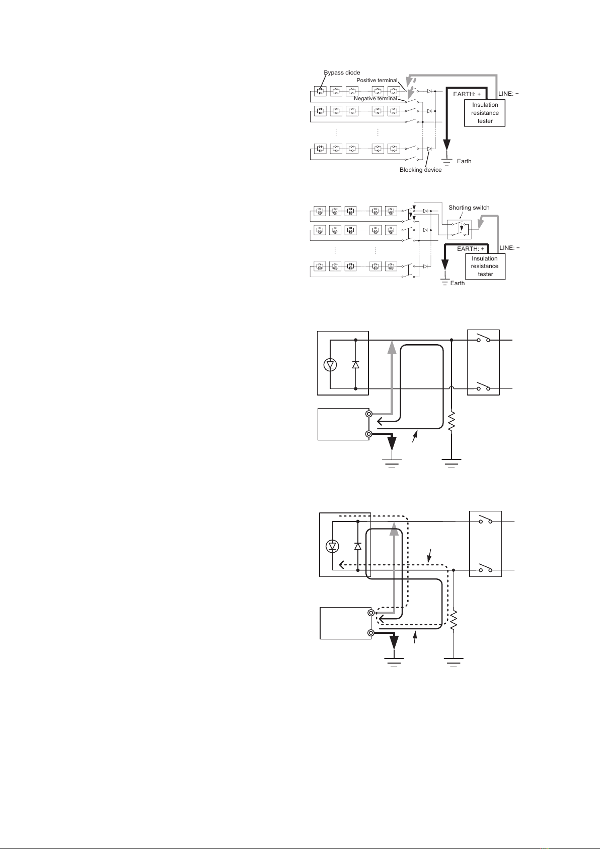
B. Measurement of Solar Panel Insulation Resistance
The technical report JEM-TR228, Maintenance and
inspection guidelines for photovoltaic power generating
systems up to 50 kW for low-voltage network (Japanese),
published by The Japan Electrical Manufactures’
Association, provides important information about the
maintenance and inspection of solar power systems. The
guidelines describe the measurement methods in addition
to the maintenance and inspection items of small-scale solar
power systems, and they recommend that the insulation
resistance of relay terminal boxes (junction boxes and power
Abstract—The Insulation Tester IR4053 is an insulation
tester designed for use in the maintenance of solar power
system equipment. This paper describes the product’s features,
architecture, and other characteristics.
I. IntroductIon
Due in part to rising awareness of environmental issues,
increasingly serious power shortages, and Japan’s national
initiatives to promote use of solar power in recent years,
there has been rapid growth in use of solar power systems,
from small-scale residential setups to large-scale megasolar
installations. These developments are driving growing
demand for equipment maintenance.
To prevent accidents caused by faulty insulation during
installation and regular inspections of solar power systems,
it is necessary to check the state of insulation by measuring
the insulation resistance at various points in the system.
When using a standard insulation tester to accomplish this
task, the technician must cut off power to the measurement
target before measuring the insulation resistance. In the
case of solar panels, insulation resistance must be measured
while the system is at a dangerous voltage since electricity
is always generated while the system is exposed to sunlight
during the day. Consequently, technicians must exercise a
high level of caution with regard to the hazard of electrical
shock while measuring insulation resistance. In addition,
it is sometimes not possible to obtain accurate resistance
insulation values when a standard insulation tester is used
to test a solar power system because the voltage produced by
the solar panels affects the measurement results.
It was against this backdrop that Hioki developed the
Insulation Tester IR4053 as an instrument that is able to
safely and accurately measure the insulation resistance of
solar panels.
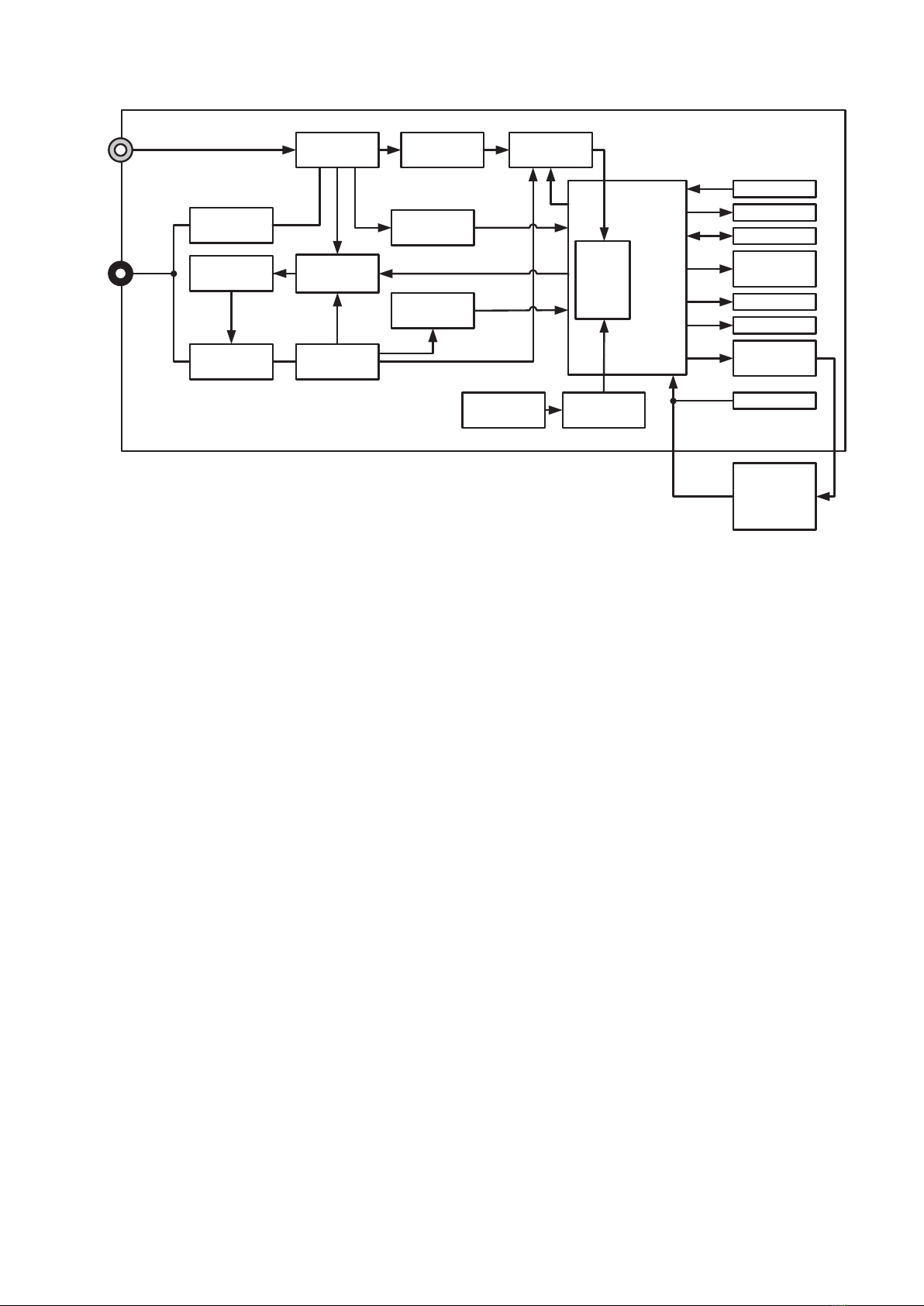
II. overvIew
A. Overview of the IR4053
The IR4053 is a portable digital insulation tester.
Developed to be capable of measuring the insulation
resistance of solar panels safely, accurately, and quickly, it is
ideal for maintenance of solar power systems.
The instrument features a new photovoltaic resistance
function designed specically to measure the insulation
resistance of solar panels. This function makes it possible
to accurately measure insulation resistance free from the
effects of the electricity being produced by the panel under
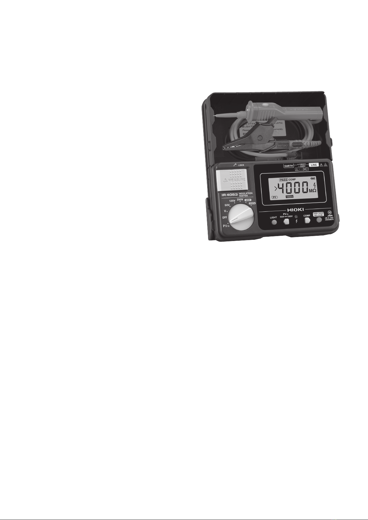
Insulation Tester IR4053
Takeaki Miyazawa
Engineering Division 5, Engineering Department
Appearance of the IR4053.