Hioki BT3554-50 User manual

BT3554-50
BT3554-51 Instruction Manual
BATTERY TESTER
EN
Sept. 2021 Revised edition 3
BT3554F961-03 21-09H
Read carefully before use.
Keep for future reference.
BT3554-52
HIOKI BT3554F961-03
www. .com information@itm.com1.800.561.8187

Let’s start by measuring a fresh battery
To evaluate whether batteries have deteriorated, measure the
internal resistance of a fresh battery. Deteriorated batteries will have
about 1.5 to 2 times (values for reference purposes) as high internal
resistance as a fresh one. Use these values as guidelines when
determining deterioration evaluation values.
Example: Changes in the internal resistance and voltage
associated with battery deterioration
Internal resistance: 0.5 mΩ
Voltage: 2.0 V
(Example values)
1.0 mΩ(Doubled)
1.8 V (Decreased by 10%)
Resistance has
doubled . . . Deteriorated
Fresh Need
replacing
FAIL
Initial value × 2
WARNING
Initial value × 1.5
PASS
Initial value Available
charge
amount
Internal
resistance
Deterioration
evaluation value
of resistance
PassPassPassPass Fail
Battery Tester Quick Guide
BT3554F961-03
Battery Tester Quick Guide
HIOKI BT3554F961-03
www. .com information@itm.com1.800.561.8187

Basic instruction on how to use the instrument
1
Connect the test lead to the
instrument. (Black) (Red)
Hold down for
at least 1 s.
2
Turn on the instrument.
Set the date and time when using
the instrument for the rst time.
(p. 45)
3
Choose a resistance range.
(p. 49)
4
Choose a voltage range.
(p. 49)
5
Enable the automatic hold and
automatic memory functions.
(The and
segments will appear.)
When the measured values become stable, the
display will automatically freeze them.
See “3.6 Automatic Hold Function” (p. 61).
Immediately after the display freezes measured
values, the instrument will automatically save them.
See “5.3 Automatic Memory Function” (p. 89).
HIOKI BT3554F961-03
www. .com information@itm.com1.800.561.8187

6
Connect the test lead to a battery under measurement.
(Black)(Red) −
+
Saved in
internal
memory.
HIOKI BT3554F961-03
www. .com information@itm.com1.800.561.8187

Convenient functions
Comparator function
You can set threshold values to evaluate battery deterioration using
the comparator function. (p. 69)
Example of setting deterioration evaluation values
Acceptance value
Resistance: 0.5 mΩ
Voltage: 2.0 V
Warning threshold
0.75 mΩ
(Fresh battery’s value × 1.5)
1.8 V
(Fresh battery’s value × 0.9)
Rejection value
1.0 mΩ
(Fresh battery’s value × 2)
PASS WARNING FAIL
Fresh In use Need
replacing
Hold down for
at least 1 s.
Downloading measured values to your computer
You can connect the instrument and your computer using the
accompanying USB cable to download measured values. (p. 105)
HIOKI BT3554F961-03
www. .com information@itm.com1.800.561.8187

Prole information (p. 84)
Where this battery
has been installed?
1 2
“Hiokichi-kun”
Hioki’s corporate mascot
How can I help you?
3Prole information
comes in handy. Prole information?
Let me know the
details.
4
The use of prole information lets you save measured data
associating with detail information.
Concept of a data set to be saved
Prole
information Prole number 1
Location information HIOKI 1F UPS ROOM
Device information UPS 1-1
Battery number 1
Measured data Memory number A.001
Date and time 2020/4/20 13:00:00
(yyyy/mm/dd hh:mm)
Resistance value . mΩ
Voltage value . V
Temperature .°C
Comparator threshold
values
mΩ, mΩ, V
Comparison result PASS, WARNING, or FAIL
HIOKI BT3554F961-03
www. .com information@itm.com1.800.561.8187

Measurement recording prompt (p. 97)
Let’s get down
to work.
1 2
The 50th battery.
That’s it.
3The memory contains
49 data sets only . . .
One short!
I have to start from
scratch again.
4
The measurement recording prompt uses voice prompts and the
display to inform you of the battery number you are to measure
next. You can get your jobs done neatly, which will no longer require
you to start all over again.
No. 1, pass.
Next battery, No. 2.
Display
Voice prompt
HIOKI BT3554F961-03
www. .com information@itm.com1.800.561.8187

i
Contents
Battery Tester Quick Guide
Introduction.........................................................................1
Verifying Package Contents..............................................3
Options................................................................................4
Safety Information..............................................................8
Operating Precautions.....................................................12
1 Overview 23
1.1 Evaluating Battery Deterioration .................23
1.2 Overview ........................................................26
1.3 Features .........................................................28
1.4 Names and Functions of Parts ....................30
1.5 Outer Dimension Drawing............................38
2 Preparing for Measurement 39
2.1 Installing/Replacing LR6 Alkaline
Batteries.........................................................39
2.2 Attaching the Z5041 Protector.....................40
2.3 Connecting the Z3210 Wireless Adapter
(Option) ..........................................................41
2.4 Connecting the Test Lead.............................42
Bundling up the Pin Type Lead and the 9466
Remote Control Switch.............................................43
2.5 TurningOn/OtheInstrument .....................44
2.6 Setting the Date and Time............................45
2.7 Attaching the Neck Strap .............................46
HIOKI BT3554F961-03
www. .com information@itm.com1.800.561.8187

ii
Contents
3 Measurement 47
3.1 Inspection Before Measurement..................48
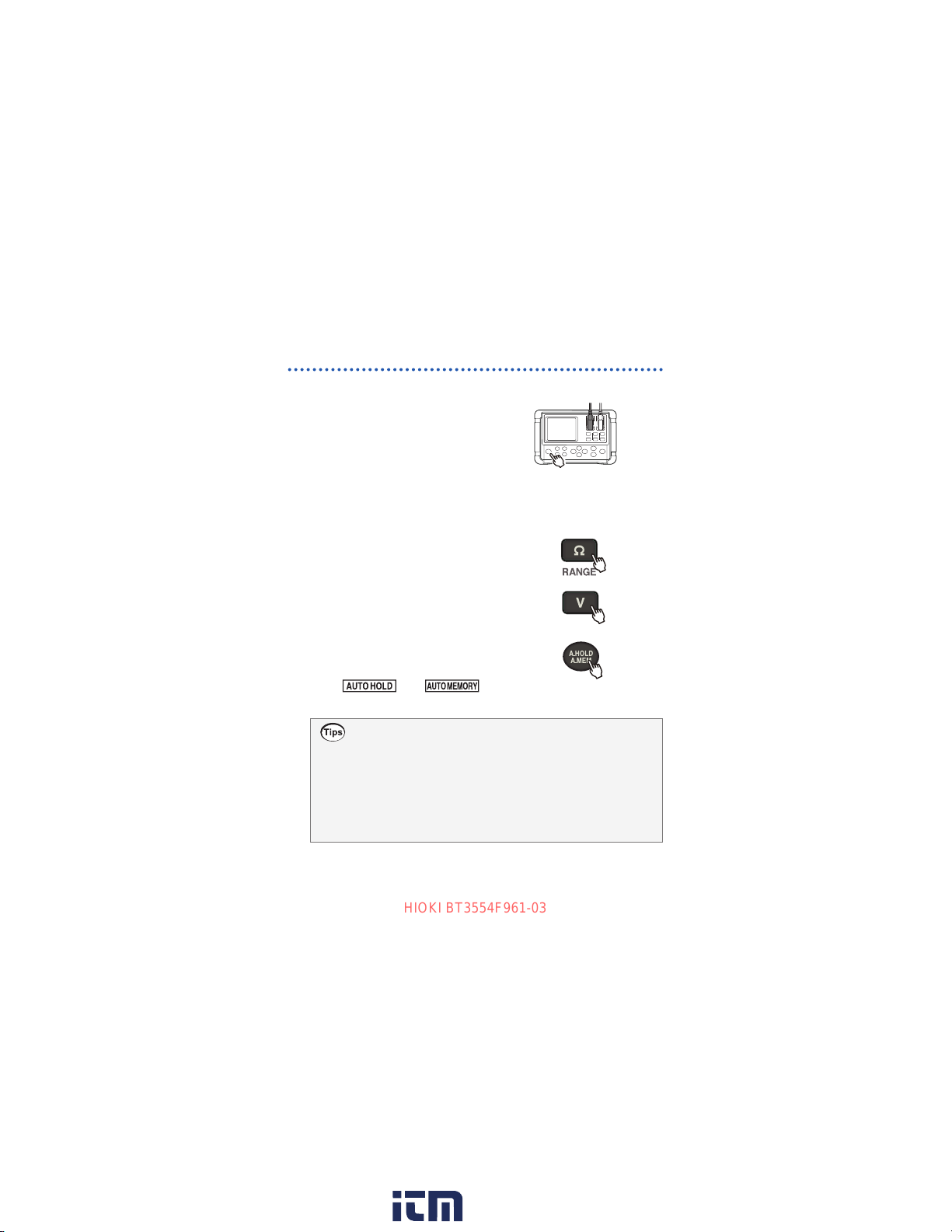
3.2 Setting the Measurement Ranges ...............49
3.3 Noise-Frequency Reduction Function ........51
3.4 Adjusting the Zero Point
(Zero Adjustment) .........................................52
How to short-circuit various test lead........................53
Performing zero adjustment......................................56
Troubleshooting on zero adjustment.........................58
Canceling the zero adjustment.................................58
3.5 Using the Hold Function...............................59
Disabling the hold function........................................59
Freezing measured values using the 9466
Remote Control Switch.............................................60
3.6 Automatic Hold Function .............................61
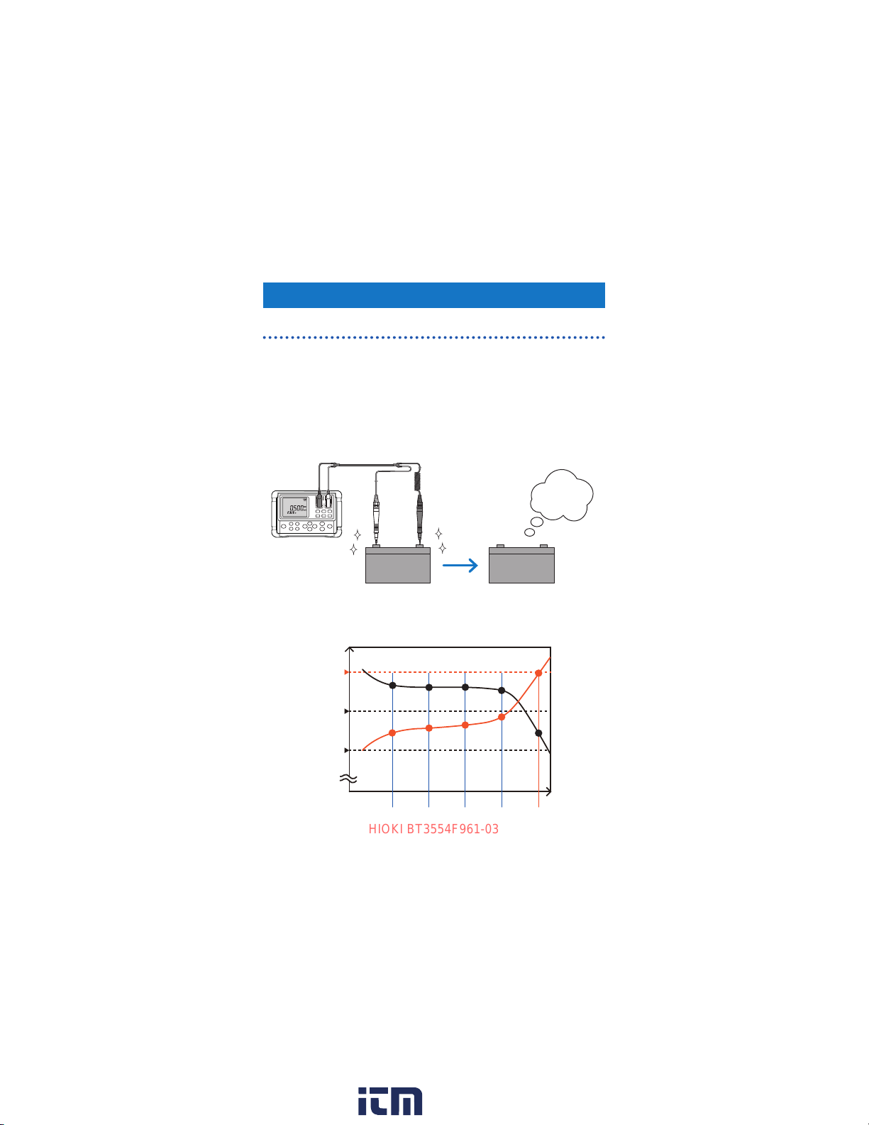
3.7 Determining Battery-Deterioration
Evaluation Values..........................................63
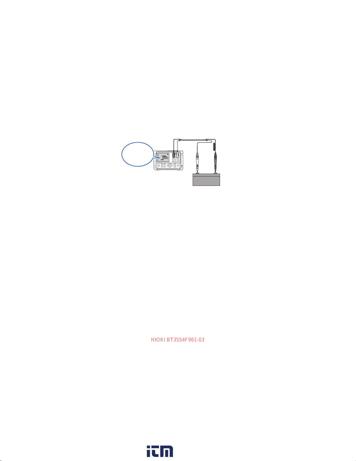
3.8 Measuring Batteries (Inspection) ................64
Measurement error...................................................67
Warning display ........................................................67
3.9 Measuring Temperature................................68
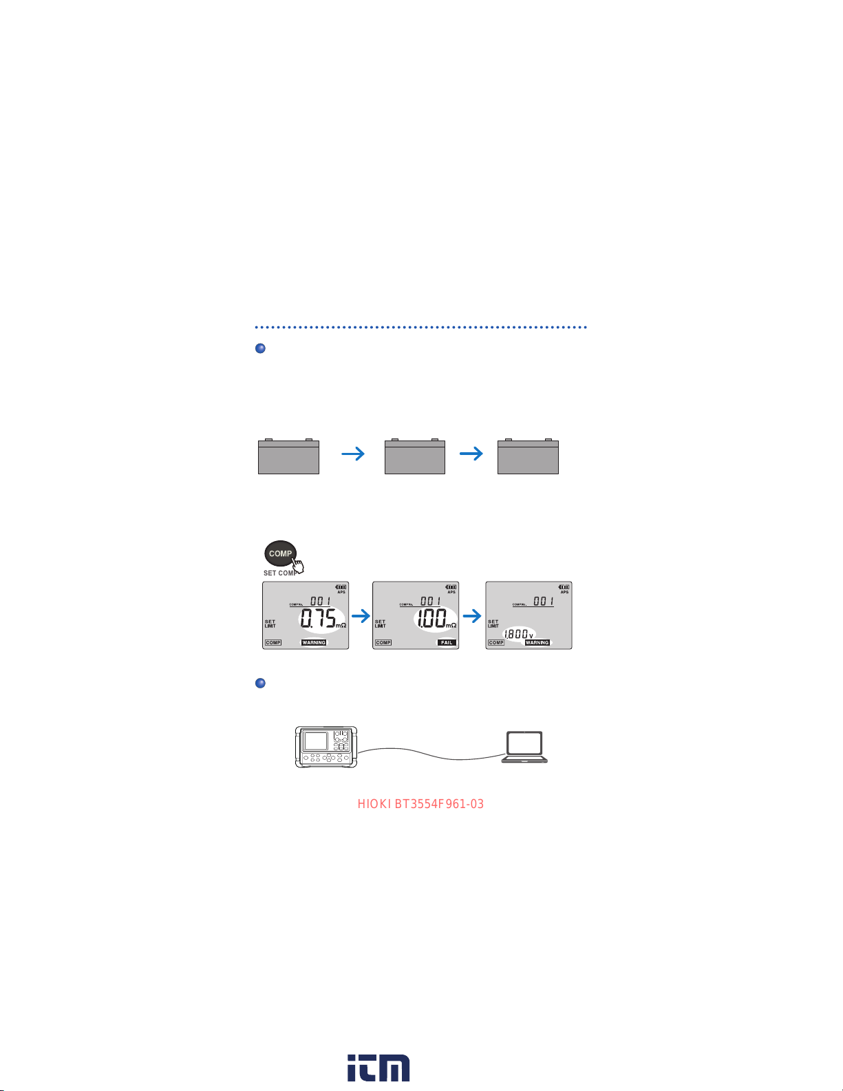
4 Comparator Function (Evaluation
Based on Threshold Values) 69
4.1 Overview ........................................................69
4.2 Enabling the Comparator Function.............70
4.3 Setting Threshold Values for the
Comparator....................................................71
Comparison table for the comparator.......................78
4.4 Setting the Comparator Buzzer ...................80
4.5 Canceling the Comparator Function...........81
HIOKI BT3554F961-03
www. .com information@itm.com1.800.561.8187

iii
Contents
5 Memory Function 83
5.1 Overview ........................................................83
Memory structure......................................................83
Prole information.....................................................84
5.2 Saving Data in the Memory ..........................87
5.3 Automatic Memory Function........................89
5.4 Disabling the Memory Function...................91
5.5 Reading Out Saved Data ..............................92
5.6 Deleting Measured Data ...............................94
Deleting a single measured data set ........................94
Deleting all data contained in a unit..........................95
Deleting entire data...................................................96
6 Measurement Recording Prompt
Function 97
6.1 Preliminary Preparation................................98
Transferring the prole information to the
instrument.................................................................98
6.2 Visual Prompt From the Instrument..........100
6.3 Visual Prompt and Voice Prompt...............103
7 Communications Function 105
7.1 Communicating With a Computer .............107
7.2 Communicating With a Mobile Device ......108
Enabling/disabling the wireless communications
function................................................................... 111
7.3 Z3210-to-Excel®Direct Data Entry
Function
(Excel®Direct Input Function, HID
Function)......................................................112
Enabling/disabling the HID function........................113
HIOKI BT3554F961-03
www. .com information@itm.com1.800.561.8187

iv
Contents
8 Other Features 115
8.1 Backlight......................................................115
Turning on/o the backlight.....................................115
Enabling/disabling automatic backlighing
shuto .....................................................................115
8.2 Automatic Power Saving Function
(APS) ............................................................116
8.3 Instrument’s Battery Level Indicator.........118
8.4 System Reset...............................................119
Default settings (Factory-congured settings) ........120
9 Specications 121
9.1 GeneralSpecications ...............................121
9.2 BasicSpecications ...................................123
9.3 AccuracySpecications.............................125
9.4 FunctionSpecications..............................127
9.5 Default Settings and Resettable
Settings........................................................139
10 Maintenance and Service 141
10.1 Repair, Inspection, and Cleaning...............141
10.2 Troubleshooting..........................................143
Before returning the instrument for repair...............143
10.3 Error Messages ...........................................146
10.4 FAQ...............................................................148
10.5 Replacing the Fuse .....................................149
10.6 Replacing the Tip Pin of the Test Lead .....150
10.7 Disposing the Instrument
(Removing the Lithium Battery).................153
HIOKI BT3554F961-03
www. .com information@itm.com1.800.561.8187

v
Contents
11 Appendix 155
11.1 EectsofExtendingtheTestLeadand
Induced Voltage...........................................155
How to reduce induced voltages.............................155
11.2 EectsofEddyCurrents ............................156
11.3 AC Four-Terminal Method
Measurement...............................................157
11.4 EectsofCurrentDensity ..........................159
When an object under measurement is wide or
thick ........................................................................159
11.5 Synchronous Detection..............................162
11.6 Calibration ...................................................164
Calibrating the resistance measurement unit .........164
Calibrating the voltage measurement unit..............165
Index 167
WarrantyCerticate
HIOKI BT3554F961-03
www. .com information@itm.com1.800.561.8187

1
Introduction
Introduction
Thank you very much for choosing the Hioki BT3554-50, BT3554-
51, BT3554-52 Battery Tester. To ensure your ability to get the most
out of this instrument over the long term, please read this manual
carefully and keep it available for future reference.
Model
number
(Order code)
Model name printed on
the instrument Standard accessory lead
BT3554-50
BT3554-50
None
BT3554-51 9465-10 Pin Type Lead
BT3554-52 L2020 Pin Type Lead
Hereafter, the model number is referred to as the one that appears
on the product, BT3554-50.
Latest edition of instruction manual
The contents of this manual are subject to change,
for example as a result of product improvements or
changes to specications.
The latest edition can be downloaded from Hioki’s
website.
https://www.hioki.com/global/support/download
HIOKI BT3554F961-03
www. .com information@itm.com1.800.561.8187

2
Introduction
Trademarks
• Android, Google Play, and Google Chrome are trademarks of Google, Inc.
• IOS is a registered trademark of Cisco Systems, Inc. and/or its aliates in
the United States and certain other countries.
• Windows and Microsoft Excel are either registered trademarks or
trademarks of Microsoft Corporation in the United States and other
countries.
• The Bluetooth®word mark and logos are registered trademarks owned by
Bluetooth SIG, Inc. and any use of such marks by Hioki E.E. Corporation
is under license. Other trademarks and trade names are those of their
respective owners.
• Other products and company names are trade names, registered
trademarks, or trademarks of their respective owners.
HIOKI BT3554F961-03
www. .com information@itm.com1.800.561.8187

3
Verifying Package Contents
When you open the package, carefully inspect the instrument to
ensure that everything is in good condition, and that no damage
occurred during shipping. In particular, check the accessories, panel
switches, and connectors. If the instrument seems to have been
damaged or does not work as specied, contact your authorized
Hioki distributor or reseller.
Conrm that these contents are provided.
LR6 Alkaline batteries ×8
Pin Type Lead
9465-10 (For BT3554-51)
L2020 (For BT3554-52)
Not included
(For BT3554-50)
USB cable
Zero-adjustment board
BT3554-50 Battery Tester
(With the Z5041 Protector
attached)
Neck strap
(p. 46)
C1014 Carrying Case
Instruction Manual
Application Software CD*
(SF4000 GENNECT ONE)
Z5050 Fuse Set
*: The latest version can be downloaded from our website.
HIOKI BT3554F961-03
www. .com information@itm.com1.800.561.8187

4
Options
Options
The options listed below are available for the instrument. To order
an option, contact your authorized Hioki distributor or reseller.
Options are subject to change. Please check Hioki’s website for
the latest information. Please check Hioki’s website for the latest
information.
Model 9465-10 Pin Type Lead
This pin type lead has a four-
terminal structure.
Model L2020 Pin Type Lead
This pin type lead has a four-
terminal structure and can be used
for hard-to-reach measurement
targets.
Model 9465-90 Tip Pin
The 9465-90 is a replacement tip
pin for the 9465-10 and L2020 Pin
Type Lead.
φ2.7 mm
φ1.27 mm
HIOKI BT3554F961-03
www. .com information@itm.com1.800.561.8187

5
Options
Model 9772 Pin Type Lead
This pin type lead has parallel
arranged pins. The pins possess
high-strength wear-resistant.
This lead, having the pins that
can be inserted into a hole 5 mm
in diameter, lets you perform
measurement without removing
terminal covers. You can also
perform measurement in virtually
any location because the pins can
be inserted diagonally in hard-to-
reach places.
Model 9772-90 Tip Pin
The 9772-90 is a replacement tip
pin for the 9772 Pin Type Lead. 9.15 mm
2.5 mm
φ1.8 mm
4.3 mm
Model 9460 Clip Type Lead with
Temperature Sensor
Using the 9460 lets you measure
resistance, voltage, and
temperature simultaneously.
Temperature
sensor
Clip (Black) Mini plug
(Connect to TEMP.SENSOR)
HIOKI BT3554F961-03
www. .com information@itm.com1.800.561.8187

6
Options
Model 9466 Remote Control
Switch
Attaching the 9466 to the test lead
lets you freeze displayed values
during measurement.
Supported models:
• Model 9465-10 Pin Type Lead
• Model 9772 Pin Type Lead
• Model L2020 Pin Type Lead
Switch
Mini plug φ2.5 mm
(Connect to EXT.HOLD)
Model 9467 Large Clip Type Lead
The 9467 can clip on thick rodlike
terminals of measurement targets.
You can perform four-terminal
measurement just by clipping the
lead on to the target.
Approx. φ29 mm
Model 9451 Temperature Probe
(Cable length: 1.5 m)
Connect the 9451 to the TEMP.
SENSOR terminal on the top face
of the instrument.
HIOKI BT3554F961-03
www. .com information@itm.com1.800.561.8187

7
Options
Model 9451S Temperature Probe
Order code: 9451-01
(Cable length: 0.1 m)
Connect the 9451S to the TEMP.
SENSOR terminal on the top face
of the instrument.
Model Z5038 0 Adj Board
(For the 9465-10, L2020, and
9772)
Hook-and-loop fasteners are
separately necessary to stick the
Z5038 to the carrying case. Please
use commercially available hook-
and-loop fasteners.
Model Z5050 Fuse Set
Always use the specied fuse.
Model Z3210 Wireless Adapter
Model C1014 Carrying Case
Model Z5041 Protector
HIOKI BT3554F961-03
www. .com information@itm.com1.800.561.8187

8
Safety Information
Safety Information
This instrument is designed to conform to IEC 61010 Safety
Standards, and has been thoroughly tested for safety prior to
shipment. However, using the instrument in a way not described in
this manual may negate the provided safety features.
Carefully read the following safety notes before using the
instrument.
DANGER
Mishandling the instrument could result in bodily
injury or even death, as well as damage to the
instrument. Familiarize yourself with the instructions
and precautions in this manual before use.
WARNING
Electricity can potentially cause serious events such
as an electric shock, heat generation, re, and an arc
ash due to a short-circuit. If you have not used any
electrical measuring instruments before, you should
be supervised by a technician who has experience in
electrical measurement.
Protective gear
WARNING
Performing measurement using this instrument
involves live-line work. To prevent an electric shock,
use appropriate protective insulation and adhere to
applicable laws and regulations.
HIOKI BT3554F961-03
www. .com information@itm.com1.800.561.8187
Other manuals for BT3554-50
1
This manual suits for next models
2
Table of contents
Other Hioki Test Equipment manuals

Hioki
Hioki FT3470-51 User manual

Hioki
Hioki 8860-50 User manual

Hioki
Hioki IR4055 User manual

Hioki
Hioki Power HiTester 3193 User manual

Hioki
Hioki 3441 User manual

Hioki
Hioki P2000 User manual

Hioki
Hioki 3286 User manual

Hioki
Hioki SS9000 User manual

Hioki
Hioki BT3554 User manual

Hioki
Hioki MR8827 User manual