Hobo U12 User manual

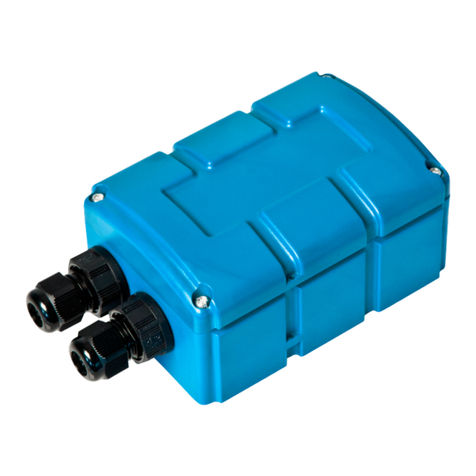
HOBO®U12 4-External Channel
Outdoor/Industrial Data Logger
(Part # U12-008)
© 2009 Onset Computer Corporation
Part #: MAN-U12008, Doc #: 13132-A
Inside this package:
•HOBO U12 4-External Channel Outdoor/Industrial Data Logger
•Desiccant pack
•Mounting/spare parts kit: Allen wrench, dome plug and O-ring, four
mounting screws, and four flat washers
Thank you for purchasing a HOBO data logger. With proper care, it will give
you years of accurate and reliable measurements.
The HOBO U12 4-External Channel Outdoor/Industrial data logger has a 12-
bit resolution and can record up to 43,000 measurements or events. The four
external channels accept a variety of sensors, including temperature and split-
core AC current sensors as well as 4-20 mA and voltage input cables (sold
separately). The logger uses a direct USB interface for launching and data
readout by a computer.
An Onset software starter kit is required for logger operation. Visit www.onsetcomp.com for compatible software.
Specifications
Measurement range External input channels (see sensor manual): 0 to 2.5 DC Volts
Accuracy
(logger only) ± 2 mV ± 2.5% of absolute reading
± 2 mV ± 1% of reading for logger-powered sensors
Resolution 0.6mV
Time accuracy ± 1 minute per month at 25°C (77°F), see Plot A
Operating range -20 to 70°C (-4° to 158°F)
Weatherproof case tested to NEMA 6 standard
Operating temperature Logging: -20° to 70°C (-4° to 158°F)
Launch/readout: 0° to 50°C (32° to 122°F), per USB specification
Battery life 1 year typical use (see “Battery” details on last page)
Memory 64K bytes (43,000 12-bit measurements)
Weight 200 g (7 oz)
Dimensions 140 x 137 x 32 mm (5.5 x 5.38 x 1.25 inches)
The CE Marking identifies this product as complying with all relevant directives in
the European Union (EU).
Plot A

HOBO U12 4-External Channel Outdoor/Industrial Data Logger
© 2009 Onset Computer Corporation
Part #: MAN-U12008, Doc #: 13132-A
Accessories
•Replacement Parts Kit (Part # H8X4-BK)
•Replacement Desiccant (Part # DESIC-PACK)
•U-Bolt (Part # U-BOLT-KIT)
4-20mA Input cable
This cable (part number CABLE-4-20mA) measures current from 0 to 20.1 mA. Do not expose to current above 20 mA or
to negative current. Do not cut off the end of the gray cable where it connects to the blue and yellow wires, as it contains the
precision resistor required for current measurement. If you are using this cable outdoors, you will need to ensure that the
connection to your sensor or device is also weatherproof. The connection between the gray cable and yellow and blue wires
is splash-proof, but not weatherproof.
Voltage input cable
The logger’s external inputs can accept the voltage input cable (Onset part number CABLE-2.5-STEREO), which allows a
voltage to be recorded. The input line must not be exposed to signals below 0 V or above 2.5 V. If you are using this cable
outdoors, you will need to ensure that the connection to your sensor or device is also weatherproof.
Voltage Input Cable Connections
Wire Connection
Red Switched 2.5 V output
White Voltage input
Black Ground
Other external sensors
Onset has a range of external temperature sensors, AC current sensors, and cables for incorporating other sensors that are
compatible with the U12 4-External Channel Data Logger. Measurement specifications for using Onset temperature and AC
current sensors with this logger are provided in the sensor manuals. For compatible sensors, refer to the HOBO catalog,
contact Onset Computer Corporation, or contact an Onset Authorized Dealer.
Switched 2.5 V output
The external input channels have a switched 2.5 V output. This signal can be used to power a sensor directly, or it can be
used to trigger an external circuit. External sensors should draw no more than 4 mA total when powered. The switched 2.5
V output turns on about 21 ms before the external channels are measured and stays powered for 1 ms after the external
channels are measured, as shown in the diagram. The grey area shows the 16 ms period during which the logger samples the
input signals.
When using multiple voltage and/or current inputs, the (-) from your current source(s) and the 0 V line of your voltage
source(s) are tied together at the logger. If these lines are at different voltage potentials, this may cause inaccurate readings
or even damage your logger. Keep in mind that these lines may also be tied to earth ground through your PC interface cable
when connected to your computer. Special precautions may be necessary if any of your voltage or current source common
lines are not tied to earth ground. Input isolators may be needed in industrial environments to prevent errors caused by
ground loops.

HOBO U12 4-External Channel Outdoor/Industrial Data Logger
3
Attaching the Sensors
1. Use the Allen wrench to remove the four socket head screws on the logger’s cover. Then remove the cover.
2. Using a 15 mm wrench, remove the dome nut for the channel you wish to connect to.
3. Pull the exposed end of the black rubber plug to remove it from the fitting. Do not throw these plugs away! These
plugs are needed to maintain a weatherproof seal for channels that are not connected to sensors or input cables.
4. Slide the dome nut over the plug end of the cable. The dome nut’s threads should face towards the case.
5. Feed the plug end of the cable from the outside of the case through the dome fitting of the channel you want to use
(refer to label on the logger’s cover) and plug it into the corresponding port as shown in the diagram. If you have
difficulty inserting the plug through the fitting, a small amount of dishwashing liquid can be used as a lubricant on the
plug. (Do not use O-ring lubricant.)
6. Thread the dome nut back onto fitting and hand-tighten it. Tighten an additional half-turn with a 15 mm wrench.
7. Make sure the desiccant cartridges are fresh. (If you are using the logger for the first time, remove the two desiccant
cartridges from the foil pouch and install them in the cavity at the top of the case.) Cartridges are blue when new, and
fade to pale pink when they need to be replaced. If they are pale pink, discard them and replace them with two new
(blue) ones (part # DESIC-PACK).
8. Close the logger’s case as described in the “Closing the logger” section of this manual.
Replacing Desiccant Cartridges
Periodically check the desiccant cartridges by looking through the viewing window on the logger’s case. The cartridges are
blue when new, and fade to pale pink when they need to be replaced. Discard the old cartridges and replace them with two
new blue ones (part # DESIC-PACK).

HOBO U12 4-External Channel Outdoor/Industrial Data Logger
4
Connecting the Logger
The U-Family logger requires an Onset-supplied USB interface cable to connect to the computer. If possible, avoid
connecting at temperatures below 0°C (32°F) or above 50°C (122°F).
1. Using a screwdriver, small coin, or similar object, turn the dome plug counter-clockwise and set it aside.
2. Plug the large end of the USB interface cable into a USB port on the computer.
3. Plug the small end of the USB interface cable into the logger as shown in the diagram. (You may find it easier to see the
port if the logger’s cover is off.)
If the logger has never been connected to the computer before, it may take a few seconds for the new hardware to be
detected. Use the logger software to launch and read out the logger.
After you disconnect the logger from the computer, remember to put back the dome plug. Make sure that the dome plug O-
ring is still in place. Then, turn the dome plug clockwise until the O-ring is snug.
Launching the Logger
Be sure to plug the external sensors into the logger before launching. Also select the correct sensors and activate the external
channels in the logger software when configuring the launch. Important: If you select an external channel, but do not
plug the probe in, false data will be recorded for that channel.
If you configured the logger to start with a button start, press and hold down the button on the front of the logger for at least
three seconds when you want to begin logging data. Then close the logger’s cover.
You can read out the logger while it continues to log, stop it manually with the software, or let it record data until the
memory is full.
Refer to the software user’s guide for complete details on launching, reading out, and viewing data from the logger.
Protecting the Logger
Static electricity may cause the logger to stop logging. To avoid electrostatic discharge, transport the logger in an anti-
static bag, and ground yourself by touching an unpainted metal surface before handling the logger. For more information
about electrostatic discharge, visit our website at http://www.onsetcomp.com/Support/support.html.

HOBO U12 4-External Channel Outdoor/Industrial Data Logger
5
Closing the Logger
Follow these steps to ensure a secure, weatherproof seal.
1. Make sure the dome plug is in place.
2. Inspect the large O-ring around the face of the logger. It should be clean, lubricated, and fully seated into the groove. (O-
ring lubricant is available from Onset Computer; part # 85-SEALANT.)
3. Place the cover on the case. The clear area on the label should be positioned over the desiccant cavity.
4. Attach the cover loosely using the four socket head screws. Make sure the O-ring is still seated properly.
5. Starting at any corner, tighten a socket head screw, then tighten the screw in the opposite corner. Tighten the two
remaining screws and inspect O-ring through the clear cover to ensure proper sealing all around. Make sure all four
screws are in place.
Sample and Event Logging
The logger can record two types of data: samples and events. Samples are the sensor measurements recorded at each logging
interval (for example, the temperature every minute). Events are independent occurrences triggered by a logger activity.
Examples of events recorded asynchronously during deployment include when the logger is connected to the host, when the
battery is low, the end of a data file once the logger is stopped, and button pushes (if applicable).
Since you must remove the logger’s cover to access the button, button pushes should be done only if the logger is
adequately protected from moisture and other environmental factors that could damage it. To mark an event, press the
button for at least one second. Both a button up and a button down event will be recorded.
The logger stores 64K of data, and can record up to 43,000 samples and events combined.

HOBO U12 4-External Channel Outdoor/Industrial Data Logger
6
Operation
A light (LED) on the front of the logger confirms logger operation. The following table explains when the logger blinks
during logger operation:
When: The light:
The logger is logging Blinks once every one to four seconds (the shorter the logging interval,
the faster the light blinks); blinks when logging a sample
The logger is awaiting a start because
it was launched in Start At Interval,
Delayed Start, or Button Start mode
Blinks once every eight seconds until launch begins
The button on the logger is being
pushed for a Button Start launch Blinks once every second while pressing the button and then flashes
rapidly once you release the button. The light then reverts to a blinking
pattern based on the logging interval
Mounting
Four mounting screws and washers are included with your logger. Use these screws to mount the logger to a wooden post.
UV-stable tie wraps also work well.
U-bolt clamps (part # U-BOLT-KIT) are preferred for mounting to a 1" pipe (1.3" outside diameter), as shown.

HOBO U12 4-External Channel Outdoor/Industrial Data Logger
7
The Battery
The logger requires one 3-Volt CR-2032 lithium battery. Expected battery life varies based on the temperature and the
frequency at which the logger is recording data (the logging interval). A new battery will typically last one year with
logging intervals greater than one minute. Deployments in extremely cold or hot temperatures or logging intervals faster
than one minute may significantly reduce battery life. Onset recommends that you install a fresh battery before every
deployment if temperatures below 0°C (32°F) are expected.
To replace the battery:
1. Disconnect the logger from the computer.
2. Use the Allen wrench to remove the four socket head screws on the logger’s cover. Then remove the cover.
3. Carefully insert a thin screwdriver blade between the edge of the battery and the battery contact that is farther from the
red LED. Gently pry up the edge of the battery, popping it out of the holder.
4. Slide the new battery, positive side up, under the two small tabs of the contact that is closer to the red LED. Press down
on the battery until it snaps into place. The logger’s LED will blink several times.
5. When the new battery is secure, close the logger’s case as described in the “Closing the logger” section of this manual.
WARNING: Do not cut open, incinerate, heat above 85°C (185°F), or recharge the lithium battery. The battery may
explode if the logger is exposed to extreme heat or conditions that could damage or destroy the battery case. Do not dispose
of the logger or battery in fire. Do not expose the contents of the battery to water. Dispose of the battery according to local
regulations for lithium batteries.
© 2009 Onset Computer Corporation. All rights reserved.
Onset and HOBO are registered trademarks of Onset Computer Corporation. Other products and brand names may be trademarks or
registered trademarks of their respective owners.
This manual suits for next models
1
Table of contents
Other Hobo Data Logger manuals
Hobo
Hobo U30 User manual
Hobo
Hobo MX2306 User manual
Hobo
Hobo RX3000 Series User manual
Hobo
Hobo MX1104 User manual
Hobo
Hobo RXMOD-RXW Series User manual
Hobo
Hobo MicroRX RX210 Series User manual
Hobo
Hobo UX90-002 Series User manual
Hobo
Hobo MicroRX RX210 Series User manual
Hobo
Hobo MX series User manual

Hobo
Hobo UX100-023 User manual

Hobo
Hobo MX1104 User manual

Hobo
Hobo MX1104 User manual
Hobo
Hobo MicroRX Station RX2103 User manual
Hobo
Hobo U12-012 User manual
Hobo
Hobo Event User manual
Hobo
Hobo MX TidbiT Ext Temp User manual
Hobo
Hobo MX1101 User manual
Hobo
Hobo Pro v2 U23-001A User manual
Hobo
Hobo UX100-023A User manual
Hobo
Hobo MX2300 Series User manual
