manuals.online logo
Brands
  1. Home
  2. •
  3. Brands
  4. •
  5. Honeywell
  6. •
  7. Keypad
  8. •
  9. Honeywell SEC-H-INT-KP User manual

Honeywell SEC-H-INT-KP User manual

INSTALLATION INSTRUCTIONS
62-0272-01
SEC-H-INT-KP SmartKey
This document covers the mounting and wiring of the SEC-H-
INT-KP remote intrusion arming display/keypad (SmartKey) in
a Honeywell Security Appliance system, hosted by a security
controller (SEC-H-201 or SEC-H-600 model controller).
Description
The SEC-H-INT-KP is a remote intrusion display/keypad used
to arm, disarm, and monitor intrusion zones. The integral
graphic LCD display features a white backlight, and 128 X 64
resolution. The keypad features a blue backlight, 4 function
keys, and 12 data keys.
Notes
• This device is intended for installation in secure indoor
locations only. Operating temperature range is 14°F to
131°F (-10°C to 44°C).
• Power this device using the 12 VDC reader output of the
SEC-H-201, SEC-H-600, or SEC-H-R2R reader expansion
module. Device current draw is 150mA. See the
“Estimating Power and Battery Requirements” section in
the installation guide for the security controller to determine
power supply, battery, and cable requirements.
• Communication to the SmartKey device is via an RS-485
port wired to an NPB-2X-485 option card installed in the
Option Card 2 slot of the security controller. Refer to the
NPB-2X-485 Option card installation sheet for details. Note
that the SmartKey does NOT communicate on the same
RS-485 bus as the SEC-H-R2R and SEC-H-RIO modules.
• A maximum of 10 SmartKeys may be installed per security
controller.
Not covered in this document is the setup and operation of
installed SEC-H-INT-KP SmartKeys. Refer to the WEBs AX
Security Controller User's Guide (number 74-4062) for this
information.
For all other related mounting and wiring details, refer to the
appropriate mounting and wiring document. See “Related
Documentation” on page 3.
Fig. 1. SEC-H-INT-KP SmartKey.
Included in this Package
Included in this package you should find the following items:
• an SEC-H-INT-KP SmartKey, with removable mounting
backplate.
• This document SEC-H-INT-KP SmartKey Installation
Instructions, Number 62-0272.
Material and Tools Required
The following supplies and tools are required for installation:
• Small wire nuts, for making wiring terminations to
SmartKey terminals.
• Suitable tools for installing wall fasteners and preparing
wires for connections.
Recommended Cable Types
The following cable types are recommended for wiring
between an SEC-H-INT-KP SmartKey and the security
controller or SEC-H-R2R module (see Figure 4 on page 3):
• RS-485 data communications: Belden 9501 (1 pair) or
9502 (2 pair), 24AWG shielded twisted-pair, or equivalent.
• 12Vdc power: Belden 9154, 1 pair 20AWG shielded
twisted-pair, or equivalent.
SMARTKEY
OVERALL DIMENSIONS
IN INCHES AND (MM):
HEIGHT: 5.12” (130)
WIDTH: 3.23” (82)
DEPTH: 0.83” (21)
COLOR: SILVER GREY
MATERIAL: ABS
M27319

SEC-H-INT-KP SMARTKEY
62-0272—01 2
MOUNTING
Mount the SEC-H-INT-KP backplate onto a wall junction box,
with wiring cable(s) passed through center opening. See
Figure 2 for dimensions.
Fig. 2. SEC-H-INT-KP backplate dimensions.
Fasten with the appropriate screws into the mounting slots.
WIRING
Only two connectors on the back of the SEC-H-INT-KP
(Figure 3) are used: J1 (Power) and J5 (RS-485 comm).
Fig. 3. Connector Detail, Rear View of SEC-H-INT-KP.
Connectors have pre-attached leads—make wiring
terminations to leads using small wire nuts. Lead colors are
shown (in parenthesis) in Figure 3.
CAUTION
Electrical Shock Hazard
Before making wiring terminations, remove power
from the security controller or SEC-H-R2R module.
Restore power only after making all wiring
terminations and fastening the SEC-H-INT-KP
SmartKey unit onto its mounted backplate.
Note that up to 10 SEC-H-INT-KP SmartKey units are
supported, where RS-485 wiring from the security controller
(NPB-2X-485 option card) is “daisy-chained” at the data J5
connector on each SmartKey. For any SmartKey installed on
either end of this RS-485 buss, set its EOL Resistor JUMPER
1 to the ON position.
Wire 12VDC power to the unit from the reader input of the
security controller, or if closer, the reader input of an SEC-H-
R2R module. Use shielded, twisted-pair cabling for all wiring,
with the shield continuously connected and grounded to earth
at one point only. See “Recommended Cable Types,” page 1.
M27320
31/64
(12)
3-5/32 (80)
Ø 1/64 (4)
1-3/16
(30)
2-23/64 (60)
31/64
(12)
5
(127)
2-23/64
(60)
31/64
(12)
31/64
(12)
1
2
3
1
2
3
1
2
3
4
5
123
1
2
3
1
2
3
45
1
2
3
4
1
2
3
5
6
1
2
3
J5
J6
J7
J1
J2
J3
J4
M27321
J5 DATA
(SHIELD) EARTH
(GREEN) DATA (–)
(YELLOW) DATA (+)
J1 POWER
(YEL/GRN) EARTH GND
(BLACK) GND
(RED) + 12V-15 VDC
SEC-H-INT-KP SMARTKEY
362-0272—01
EXAMPLE WIRING DIAGRAM
Figure 4 shows an example wiring diagram for a system using
two SEC-H-INT-KP SmartKeys. Note in this example,
SmartKey #1 is installed at the end of the RS-485 buss, on
which the security controller is daisy-chain connected on its
NPB-2X-485 option connector. From there, this SmartKey
buss continues on one pair of a 2-pair cable run to the SEC-H-
R2R module (the other pair is used for RS-485
communications between the security controller and its
expansion modules).
From the SEC-H-R2R module, another 2-pair cable is run to
the SmartKey #2 unit, which allows for RS-485 “multidrop”
wiring (using one pair to return back to the SEC-H-R2R
module). Wiring can continue in this fashion to other SEC-H-
R2R modules and SmartKey units, if needed.
Fig. 4. Example wiring diagram for system with two SEC-H-INT-KP SmartKey units.
When done wiring, insert the SEC-H-INT-KP SmartKey onto
its backplate and secure with the screw in the bottom of its
case.
Wiring Checkout
After completing wiring terminations and restoring power to
the security controller, the LCD display on the SEC-H-INT-KP
SmartKey should display time, and keys should be backlit in
blue. This verifies power to the SmartKey.
To verify RS-485 communications, refer to the WEBs AX
Security User's Guide for setup procedures.
RELATED DOCUMENTATION
For more information on mounting and wiring a WEBs
Security system, refer to the following documents:
• SEC-H-201 Security Controller Installation Guide, 95-7750
• SEC-H-600 Security Controller Installation Guide, 95-7759
• SEC-H-R2R Remote Reader Module Installation Guide,
95-7749
• SEC-H-RIO Remote I/O Installation Guide, 74-4060
• SEC-ENC-H-1 and SEC-ENC-H-2 Medium and Large
Enclosure Installation Guide, 95-7747
• SEC-ENC-H-3 Small Enclosure Installation Guide,
95-7748
For details on software configuration for a fully functioning
security system, refer to the following document:
• WEBs AX Security Controller User's Guide, 74-4062
M27322
GND
DI1
DI2
DI3
PS+
PS–
BT+
BT–
SI6
SI1
SI2
SI3
SI5
SI4
GND
GND
GND
GND
DC+
AX3
AX1
D1
AX2
D0
NC2
NO1
NC1
NO2
C1
C2
NC3
NO3
C3
NC4
NO4
C4
GND
DC+
AX3
AX1
D1
AX2
D0
PS–
PS+
BB
-
+
S
PS–
PS+
BB
-
+
S
PS–
PS+
BB
-
+
S
PS–
PS+
BB
-
+
S
SI1
SI4
SI3
SI2
GND
GND
NC2
NO1
NC1
NO2
C1
C2
AX2
DC+
D0
D1
GND
AX1
AX2
DC+
D0
D1
GND
AX1
AX3
AX3
DI2
DI1
GND
-S
+
S+-
S+-
ON
JUMPER 1
J5 1
2
3
J1 123
J5 123
J1 123
OFF
JUMPER 1
NPB-2X-485
OPTION CARD IN
OPTION SLOT 2
NPB-2X-485 OPTION
CONNECTOR PLUG
(SHOWN SCREW
SIDE UP)
SEC-H-INT-KP
SMARTKEY 1 SEC-H-INT-KP
SMARTKEY 2
EOL RESISTOR JUMPER 1
SHOULD BE IN THE ON POSITION
ON AN END UNIT ONLY
SECURITY CONTROLLER
SEC-H-R2R
TO OTHER
UNITS
CUT AND TAPE BACK SHIELD
BELDEN
9502 OR
EQUIVALENT
BELDEN
9501 OR
EQUIVALENT
PAIR 1
CUT AND TAPE
BACK SHIELD
BELDEN
9501 OR
EQUIVALENT
PAIR 2
BELDEN
9502 OR
EQUIVALENT
BELDEN 9154
OR EQUIVALENT
SEC-H-INT-KP SMARTKEY
Automation and Control Solutions
Honeywell International Inc. Honeywell Limited-Honeywell Limitée
1985 Douglas Drive North 35 Dynamic Drive
Golden Valley, MN 55422 Toronto, Ontario M1V 4Z9
customer.honeywell.com
® U.S. Registered Trademark
© 2008 Honeywell International Inc.
62-0272—01 M.S. 03-08
By using this Honeywell literature, you agree that Honeywell will have no liability for any damages arising out of your use or modification to, the
literature. You will defend and indemnify Honeywell, its affiliates and subsidiaries, from and against any liability, cost, or damages, including
attorneys’ fees, arising out of, or resulting from, any modification to the literature by you.

Other Honeywell Keypad manuals

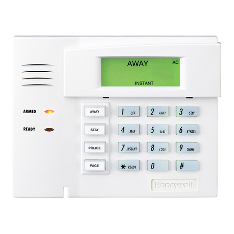
Honeywell Ademco 6150V User manual

Honeywell

Honeywell Ademco 6150V User manual

Honeywell 6280W Installation and operation manual

Honeywell

Honeywell 6280W Installation and operation manual

Honeywell ADEMCO 5828 User manual

Honeywell

Honeywell ADEMCO 5828 User manual

Honeywell PINpad RE252 User manual

Honeywell

Honeywell PINpad RE252 User manual

Honeywell ADEMCO 5828 Assembly instructions

Honeywell

Honeywell ADEMCO 5828 Assembly instructions

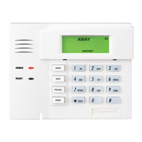
Honeywell 6150 - Ademco Fixed - Display Keypad Assembly instructions

Honeywell

Honeywell 6150 - Ademco Fixed - Display Keypad Assembly instructions

Honeywell 5828V - Ademco Wireless Talking Keypad Assembly instructions

Honeywell

Honeywell 5828V - Ademco Wireless Talking Keypad Assembly instructions

Honeywell ADEMCO 6150RF Assembly instructions

Honeywell

Honeywell ADEMCO 6150RF Assembly instructions

Honeywell 6280 Series User manual

Honeywell

Honeywell 6280 Series User manual

Honeywell Silent Knight 6820EVS User manual

Honeywell

Honeywell Silent Knight 6820EVS User manual

Honeywell ADEMCO 6152 Assembly instructions

Honeywell

Honeywell ADEMCO 6152 Assembly instructions

Honeywell Ademco 6160PX Assembly instructions

Honeywell

Honeywell Ademco 6160PX Assembly instructions

Honeywell 6160V - Ademco Talking Alpha Display Keypad User manual

Honeywell

Honeywell 6160V - Ademco Talking Alpha Display Keypad User manual

Honeywell ADEMCO 6160RF User manual

Honeywell

Honeywell ADEMCO 6160RF User manual

Honeywell Lyric LKP500-EN Assembly instructions

Honeywell

Honeywell Lyric LKP500-EN Assembly instructions

Honeywell GKP-S8M User manual

Honeywell

Honeywell GKP-S8M User manual

Honeywell Accentic proX2 Service manual

Honeywell

Honeywell Accentic proX2 Service manual

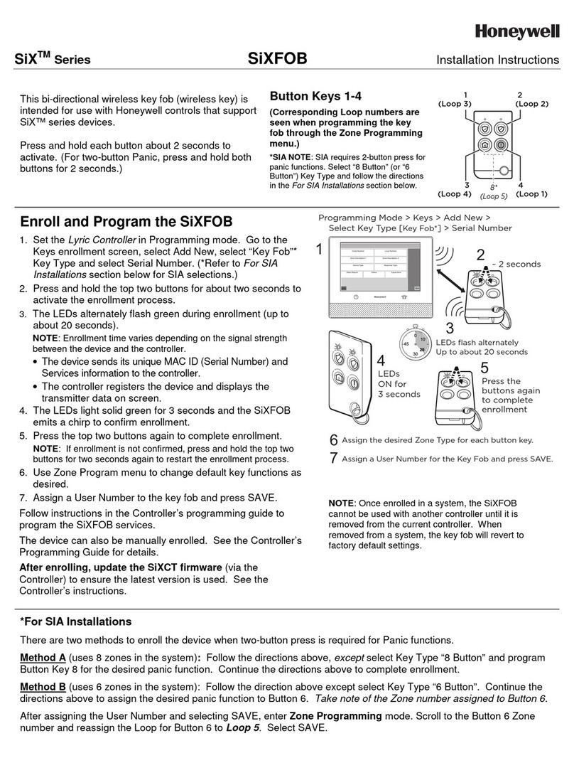
Honeywell SiX Series User manual

Honeywell

Honeywell SiX Series User manual

Honeywell 5828 Assembly instructions

Honeywell

Honeywell 5828 Assembly instructions

Honeywell 6280 Series User manual

Honeywell

Honeywell 6280 Series User manual

Honeywell ADEMCO 6152RF Assembly instructions

Honeywell

Honeywell ADEMCO 6152RF Assembly instructions

Honeywell Ademco 6460S Assembly instructions

Honeywell

Honeywell Ademco 6460S Assembly instructions

Honeywell 6162 Owner's manual

Honeywell

Honeywell 6162 Owner's manual

Honeywell 6150 - Ademco Fixed - Display Keypad Assembly instructions

Honeywell

Honeywell 6150 - Ademco Fixed - Display Keypad Assembly instructions

Popular Keypad manuals by other brands

Elk Navigator -M1KPNAV user guide

Elk

Elk Navigator -M1KPNAV user guide

Jaycar LA5155 user guide

Jaycar

Jaycar LA5155 user guide

Risco lightsys RP432KPP manual

Risco

Risco lightsys RP432KPP manual

Fortrek SPIDER VENOM 2 GK705BK Configuration guide

Fortrek

Fortrek SPIDER VENOM 2 GK705BK Configuration guide

Vanderbilt SPCK620 manual

Vanderbilt

Vanderbilt SPCK620 manual

McIntosh WK-2 installation guide

McIntosh

McIntosh WK-2 installation guide

Extel WECACV70003 Installation and user guide

Extel

Extel WECACV70003 Installation and user guide

TruVision TVK-600 Configuration manual

TruVision

TruVision TVK-600 Configuration manual

alpro AS-ATP2S200 instructions

alpro

alpro AS-ATP2S200 instructions

KEF BST30 user manual

KEF

KEF BST30 user manual

Satel INT-SF manual

Satel

Satel INT-SF manual

Digital Monitoring Products GRAPHIC TOUCHSCREEN KEYPAD user guide

Digital Monitoring Products

Digital Monitoring Products GRAPHIC TOUCHSCREEN KEYPAD user guide

Black Nova AXES Spark user manual

Black Nova

Black Nova AXES Spark user manual

NAPCO MAGNUM ALERT RP3000 KEYPAD operating guide

NAPCO

NAPCO MAGNUM ALERT RP3000 KEYPAD operating guide

APO DK-9865 MK-II Programming & installation manual

APO

APO DK-9865 MK-II Programming & installation manual

P.I. Engineering X-keys Pro product manual

P.I. Engineering

P.I. Engineering X-keys Pro product manual

CDVI GALEO 4.0 - Bluetooth installation manual

CDVI

CDVI GALEO 4.0 - Bluetooth installation manual

rako WCM-041 instruction manual

rako

rako WCM-041 instruction manual

manuals.online logo
manuals.online logoBrands
  • About & Mission
  • Contact us
  • Privacy Policy
  • Terms and Conditions

Copyright 2025 Manuals.Online. All Rights Reserved.