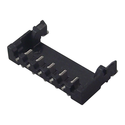
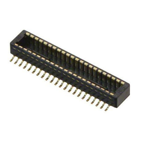
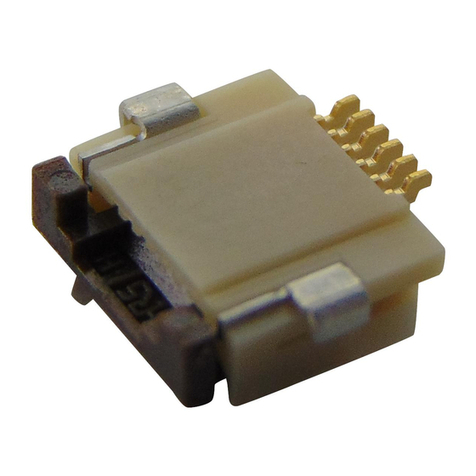
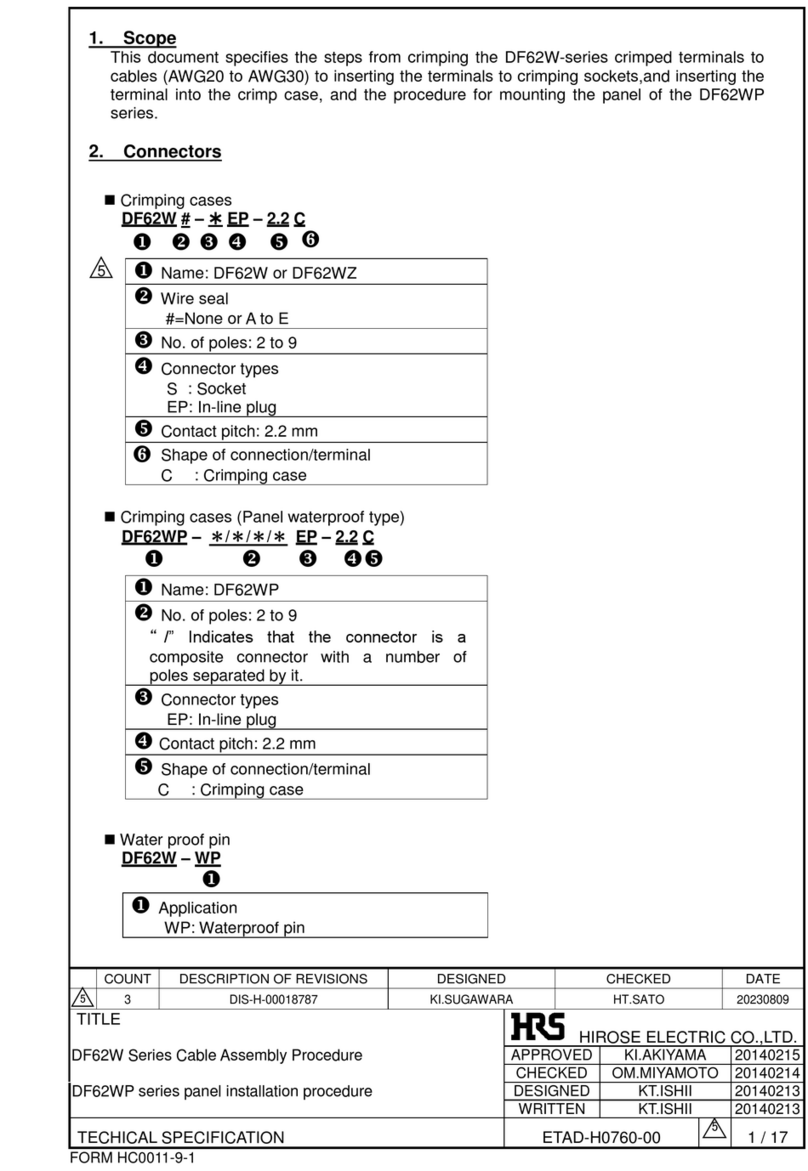
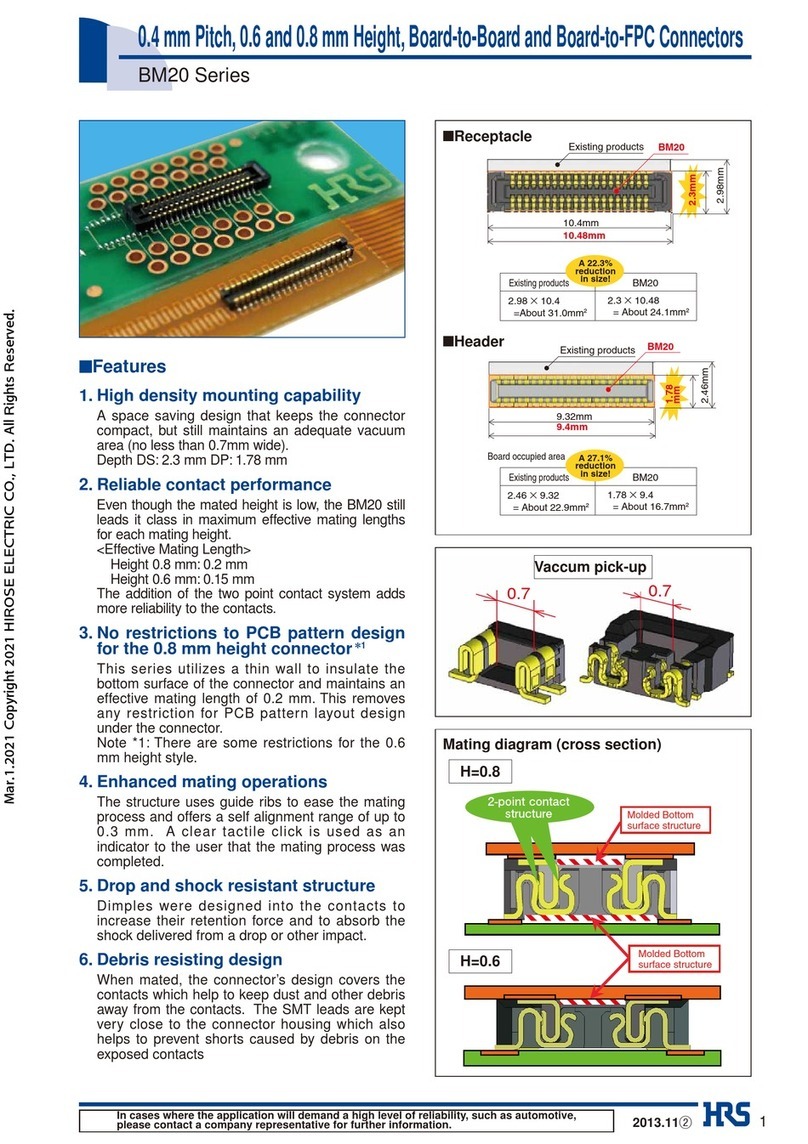
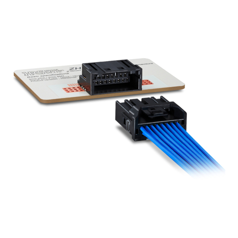
HRS BM25 Series Instruction Manual

TITLE:
BM25 Series Guideline
ETAD-H1018-00
PRODUCT:
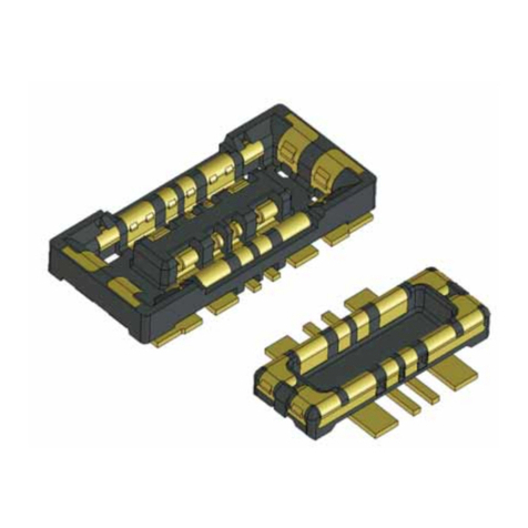
BATTERY BOARD TO FPC CONNECTOR,
Pitch: 0.4mm, Width: 2.6mm,
Stacking height: 0.7mm, Power: 10A
PAGE:
1 OF 19
HIROSE ELECTRIC CO.,LTD
BM25 Series Guideline
Approver
WR.FUKUCHI
20210402
Checker
TS.MIYAZAKI
20210402
Designer
TY.MORISHITA
20210402
REVISIONS
RevNo
0
Designer
Checker
Approver
DATE
TABLE OF CONTENTS
Power contact
Power contact
Signal contact
Nov.1.2021Copyright2021HIROSEELECTRICCO.,LTD.AllRightsReserved.

TITLE:
BM25 Series Guideline
ETAD-H1018-00
PRODUCT:
BATTERY BOARD TO FPC CONNECTOR,
Pitch: 0.4mm, Width: 2.6mm,
Stacking height: 0.7mm, Power: 10A
PAGE:
2 OF 19
HIROSE ELECTRIC CO.,LTD
Page Number
1.Notice for Device Designing............................................................................................................................3
1-1 Notice for mechanical designing..........................................................................................................3
1-1.a Disengaging prevention...............................................................................................................3
1-1.b FPC FIXING.................................................................................................................................4
1-1.c Location of other components around connector........................................................................4
1-1.d Marking for mating position .........................................................................................................4
1-2 Notice for PWB designing...................................................................................................................5
1-2.a Recommended PWB pattern.......................................................................................................6
1-2.b PWB pad layout and connector location .....................................................................................6
1-2.c PWB designing ............................................................................................................................7
1-2.d FPC designing.............................................................................................................................8
2. Notice for Mounting....................................................................................................................................10
2-1 Metal mask design ............................................................................................................................10
2-2 Reflow profile.....................................................................................................................................11
2-3 Notice for...........................................................................................................................................12
2-3.a Repairing condition .....................................................................................................................12
2-3.b Solder swelling............................................................................................................................12
3 Notice for Connector Handling
3-1 Connector insertion operation.............................................................................................................13
3-2 Connector withdrawal operation..........................................................................................................14
4 PWB for Evaluation test .................................................................................................................................15
4-1 Contact Resistance Measurement.....................................................................................................15
4-2 Temperature Rise Test.......................................................................................................................16
5 Electrical inspection jig..................................................................................................................................17
5-1 Product name ....................................................................................................................................17
5-2 Electric inspection jig summary ..........................................................................................................17
5-3 Arrangement of the electric inspection jig ...........................................................................................18
5-4 Contact information of YOKOWO CO., LTD. ....................................................................................19
Nov.1.2021Copyright2021HIROSEELECTRICCO.,LTD.AllRightsReserved.
TITLE:
BM25 Series Guideline
ETAD-H1018-00
PRODUCT:
BATTERY BOARD TO FPC CONNECTOR,
Pitch: 0.4mm, Width: 2.6mm,
Stacking height: 0.7mm, Power: 10A
PAGE:
3 OF 19
HIROSE ELECTRIC CO.,LTD
1.Notice for Device Design
1.1 Notice for mechanical designing
1-1.a Disengagement prevention
Please use buffer material.
There is still possibility that connectors are disengaged if strong impact, such as dropping, is put against
connectors inuse.In order to prevent connectors from disengaging,pleasemake sure to putbuffer material
between a connector and a cover case to hold down the connector pair to the mating direction.
If a connector is directly pressed down by a cover case, there is a possibility that the cover case is bent
and it may cause connector disengagement when the device is dropped. Please avoid a design that the
connector is directly pressed by cover case, instead, use put the buffer material to press down the
connector.
Buffer material must be the size which is able to cover all over the connector mounting area.
×
Nov.1.2021Copyright2021HIROSEELECTRICCO.,LTD.AllRightsReserved.
TITLE:
BM25 Series Guideline
ETAD-H1018-00
PRODUCT:
BATTERY BOARD TO FPC CONNECTOR,
Pitch: 0.4mm, Width: 2.6mm,
Stacking height: 0.7mm, Power: 10A
PAGE:
4 OF 19
HIROSE ELECTRIC CO.,LTD
.1-1.b FPC FIXING
Do not completely fix the FPC position.
If FPC position is fixed, connector will get direct stress from dropping impact.
1-1.c Location of other components around connector
Please do not locate any material which may affect on connector mating around the
connectors.
It may cause a misalignment or breakage.
1-1.d Marking for mating position
Putting some marking to indicate the exact mating position is recommended.
It can support smooth mating.
Boss of cover
FPC
NG
Marking for positioning
Nov.1.2021Copyright2021HIROSEELECTRICCO.,LTD.AllRightsReserved.
TITLE:
BM25 Series Guideline
ETAD-H1018-00
PRODUCT:
BATTERY BOARD TO FPC CONNECTOR,
Pitch: 0.4mm, Width: 2.6mm,
Stacking height: 0.7mm, Power: 10A
PAGE:
5 OF 19
HIROSE ELECTRIC CO.,LTD
1.2 Notice for PWB designing
1-2.a Recommended PWB pattern
Fig 1-2.a(1) Receptacle (BM25-4S/2-V) Recommended PWB layout
Fig 1-2.a(2) Plug (BM25-4P/2-V) Recommended PWB layout
Nov.1.2021Copyright2021HIROSEELECTRICCO.,LTD.AllRightsReserved.
TITLE:
BM25 Series Guideline
ETAD-H1018-00
PRODUCT:
BATTERY BOARD TO FPC CONNECTOR,
Pitch: 0.4mm, Width: 2.6mm,
Stacking height: 0.7mm, Power: 10A
PAGE:
6 OF 19
HIROSE ELECTRIC CO.,LTD
1-2.b PWB pad layout and connector location
Fig 1-2.b(1) Receptacle Positioning
Fig 1-2.b(2) Plug Position
Connector read on PWB layout
PWB layout
Connector read on PWB layout
PWB layout
Nov.1.2021Copyright2021HIROSEELECTRICCO.,LTD.AllRightsReserved.

TITLE:
BM25 Series Guideline
ETAD-H1018-00
PRODUCT:
BATTERY BOARD TO FPC CONNECTOR,
Pitch: 0.4mm, Width: 2.6mm,
Stacking height: 0.7mm, Power: 10A
PAGE:
7 OF 19
HIROSE ELECTRIC CO.,LTD
1-2.c Notice for PWB design
・Recommended PWB pattern width is 1mm(Copper foil thickness=35μm)/1A
PWB Specifications for temperature rise evaluations are as follows.
1-2c(1) PWB for temperature rise evaluations of receptacle
1-2c(2) PWB for temperature rise evaluations of plug
Material:FR-4
PAD:Recommended pattern
Recommended Power contact
pattern width:10mm
Recommended Signal contact
pattern width :0.3mm
Copper foil thickness:35μm
PWB size 70×20×0.8mm
Material:polyimide(single layer)
stiffener:FR-4
PAD:Recommended pattern
Recommended Power contact pattern
width:10mm
Recommended Signal contact pattern
width:0.3mm
Copper foil thickness:35μm
PWB size:38×11×0.435mm
*including stiffener thickness
Stiffener size:7×11×0.3mm
+10A
-10A
-10A
+10A
* Apply 0.3 Amps to each signal contact.
Power current (Amp)
Temperature rise (deg.)
Nov.1.2021Copyright2021HIROSEELECTRICCO.,LTD.AllRightsReserved.

TITLE:
BM25 Series Guideline
ETAD-H1018-00
PRODUCT:
BATTERY BOARD TO FPC CONNECTOR,
Pitch: 0.4mm, Width: 2.6mm,
Stacking height: 0.7mm, Power: 10A
PAGE:
8 OF 19
HIROSE ELECTRIC CO.,LTD
・Please design circuit of power supply pad without splitting current flow
Electric current might be concentrated in a certain circuit and cause over current
・Please design PWB layout properly so that fillet are properly formed.
The recommended PWB layout is designed so that the connector can be soldered to the PWB.
・Please comply with our recommended inner side of PWB pattern of receptacle
It may cause solder wicking.
・Please note pattern and the height of VIA hole.
In case there’s PWB pattern or VIA HOLE with too much height underneath the onnector,
there is a possibility to cause soldering failure.
Solder paste
Power supply part circuit
Inner side of PWB pattern
Nov.1.2021Copyright2021HIROSEELECTRICCO.,LTD.AllRightsReserved.
TITLE:
BM25 Series Guideline
ETAD-H1018-00
PRODUCT:
BATTERY BOARD TO FPC CONNECTOR,
Pitch: 0.4mm, Width: 2.6mm,
Stacking height: 0.7mm, Power: 10A
PAGE:
9 OF 19
HIROSE ELECTRIC CO.,LTD
1-2.d FPC design
・Please make sure to put a stiffener on the backside of the FPC.
It may cause the connector to peel-off or break.
【note】If using a thinner stiffener than our recommendation,
please contact and discuss with your Hirose contact window.
・When mounting the connector, please consider the bending of FPC by heating,
and use FPC with low risk of bending.
It may cause bending when heating.
・Please design the FPC to have a flexibility to absorb the displacement of the connecter
cased by fixing PWB and battery.
Recommended FPC Routing
Unrecommended FPC Routing
(Too short, not winding)
Recommended stiffener
FR- 4:t=0.3mm MIN
SUS:t=0.2mm MIN
Nov.1.2021Copyright2021HIROSEELECTRICCO.,LTD.AllRightsReserved.
TITLE:
BM25 Series Guideline
ETAD-H1018-00
PRODUCT:
BATTERY BOARD TO FPC CONNECTOR,
Pitch: 0.4mm, Width: 2.6mm,
Stacking height: 0.7mm, Power: 10A
PAGE:
10 OF 19
HIROSE ELECTRIC CO.,LTD
2.Notice for Mounting
2-1 Metal mask design
Make sure the latest specification when designing.
Notice:
If the soldering paste exceeds the recommended amount, there is a possibility of solder swelling.
【note】Please refer to “Solder paste swelling” on page 10.
Recommended stencil
thickness:0.10mm
Open ratio :
Signal contact:100%
Power contact:70%
Recommended stencil
thickness: 0.10mm
Open ratio:100%
Fig 2-1.(1) Recommended stencil layout of receptacle (BM25-4S/2-V)
Fig 2-1.(2) Recommended stencil layout of plug (BM25-4P/2-V)
Nov.1.2021Copyright2021HIROSEELECTRICCO.,LTD.AllRightsReserved.

TITLE:
BM25 Series Guideline
ETAD-H1018-00
PRODUCT:
BATTERY BOARD TO FPC CONNECTOR,
Pitch: 0.4mm, Width: 2.6mm,
Stacking height: 0.7mm, Power: 10A
PAGE:
11 OF 19
HIROSE ELECTRIC CO.,LTD
2-2 Reflow profile
•Profile measurement point
The temperature profile indicates the board surface temperature at the point of contacts with
the connector terminals.
•Reflow cycles
Up to 2 cycles of reflow soldering are possible under the same conditions.
*Temperature between 1st and 2nd reflow must be cooled down to room temperature.
•Reflow heating method and condition
Far-infrared heater and hot convective blowers used in combination, normal atmosphere, or
nitrogen atmosphere
・Notifications for N2reflow
Please set O2concentration more than 1000[ppm] (HRS recommendation) in SMT
Please feel free to contact us when it is less than 1000[ppm].
Fig. 2-2 Recommended reflow profile
Nov.1.2021Copyright2021HIROSEELECTRICCO.,LTD.AllRightsReserved.

TITLE:
BM25 Series Guideline
ETAD-H1018-00
PRODUCT:
BATTERY BOARD TO FPC CONNECTOR,
Pitch: 0.4mm, Width: 2.6mm,
Stacking height: 0.7mm, Power: 10A
PAGE:
12 OF 19
HIROSE ELECTRIC CO.,LTD
2-3 Repair Condition
2-3.a Repair Condition
Receptacle Plug
2-3.b Solder swelling
・Please keep the soldering paste height less than 0.02mm.
It may effect on the board to board distance.
Repairing condition:
•Soldering iron 350°C, 3seconds
MAX
Notice:
•Please do not put stress on
contacts.
•Please do not touch housing with a
soldering iron.
Repairing condition:
•Soldering iron 350°C, 3seconds
MAX
Notice:
•Please do not put stress on
contacts.
•Please do not touch housing with a
soldering iron.
•Please protect contact from flux or
soldering paste splashing
(ex. set a cover over the contact
area).
Nov.1.2021Copyright2021HIROSEELECTRICCO.,LTD.AllRightsReserved.
TITLE:
BM25 Series Guideline
ETAD-H1018-00
PRODUCT:
BATTERY BOARD TO FPC CONNECTOR,
Pitch: 0.4mm, Width: 2.6mm,
Stacking height: 0.7mm, Power: 10A
PAGE:
13 OF 19
HIROSE ELECTRIC CO.,LTD
3.Notice for Connector Handling
3-1 Connector insertion operation
Please mate BM25connectors by hand
Manual for inserting operation
1)Find the alignment area with hand to locate the connector in the appropriate mating
position.
BM25 Series have guidance ribs on receptacle side for smooth mating.
Put the connector on these ribs so that they can be self-aligned.
2)When the connector comes to the appropriate position, the connector comes into the
aligned position.
If the connector comes into aligned position, it can be recognized by hand that the connector
goes down one level.
3)Mate when the connectors are in alignment position
When the connectors are in alignment position, the connector pair cannot be moved back and
forth and around as they are mated in a parallel position.
4)Please make sure connectors are mated completely.
If one side is floating or the connectors are mated at a slant, please unmate once, and then
mate them once again, following the procedures above from the beginning.
Go down one level
Find the appropriate position
moving the connector back and
forth
Coming to the appropriate position
Nov.1.2021Copyright2021HIROSEELECTRICCO.,LTD.AllRightsReserved.

TITLE:
BM25 Series Guideline
ETAD-H1018-00
PRODUCT:
BATTERY BOARD TO FPC CONNECTOR,
Pitch: 0.4mm, Width: 2.6mm,
Stacking height: 0.7mm, Power: 10A
PAGE:
14 OF 19
HIROSE ELECTRIC CO.,LTD
3-2 Connector withdrawing operation
1)Vertical Direction
It may be difficult to unmate from vertical direction due to FPC thickness or large pin count.
2)Extraction from length direction
Please unmate the connector lifting one side of it diagonally against the contact pitch direction.
3)Extraction from width direction
When removing from width side, please pull the edge of FPC board for vertical direction.
Please avoid withdrawing the connector from width side. It may damage the contacts.
4)If the FPC is not strong enough, conduct the test on FPC to repeat operation.
If FPC is not strong enough, there is a possibility that contacts may be pulled off or broken. Please make
sure to conduct the test on FPC to repeat operation several times in an early stage build.
Nov.1.2021Copyright2021HIROSEELECTRICCO.,LTD.AllRightsReserved.
TITLE:
BM25 Series Guideline
ETAD-H1018-00
PRODUCT:
BATTERY BOARD TO FPC CONNECTOR,
Pitch: 0.4mm, Width: 2.6mm,
Stacking height: 0.7mm, Power: 10A
PAGE:
15 OF 19
HIROSE ELECTRIC CO.,LTD
4.PWB for Evaluation test
4-1 Contact Resistance Measurement
FPC Material Configuration
Copper foil thickness:35μm
◆PWB for Receptacle(FPC)
◆PWB for Plug(PWB)
Nov.1.2021Copyright2021HIROSEELECTRICCO.,LTD.AllRightsReserved.
TITLE:
BM25 Series Guideline
ETAD-H1018-00
PRODUCT:
BATTERY BOARD TO FPC CONNECTOR,
Pitch: 0.4mm, Width: 2.6mm,
Stacking height: 0.7mm, Power: 10A
PAGE:
16 OF 19
HIROSE ELECTRIC CO.,LTD
4-2 Temperature Rising Test
Material:polyimide(stratum)
reinforcing plate:FR-4
PAD:Recommended pattern
Recommended Power terminal:10mm
Recommended Signal terminal:0.3mm
Copper foil thickness:35μm
PWB size:38×11×0.435mm
*include reinforcement board pressure
reinforcing plate size:7×11×0.3mm
◆PWB for Plug(FPC)
◆PWB for Receptacle(PWB)
Material:FR-4
PAD:Recommended pattern
Recommended Power terminal:10mm
Recommended Signal terminal:0.3mm
Copper foil thickness:35μm
PWB size 70×20×0.8mm
Nov.1.2021Copyright2021HIROSEELECTRICCO.,LTD.AllRightsReserved.
TITLE:
BM25 Series Guideline
ETAD-H1018-00
PRODUCT:
BATTERY BOARD TO FPC CONNECTOR,
Pitch: 0.4mm, Width: 2.6mm,
Stacking height: 0.7mm, Power: 10A
PAGE:
17 OF 19
HIROSE ELECTRIC CO.,LTD
5.PWB for Evaluation test
About electric inspection of the connector. We recommend test connector made by YOKOWO CO.LTD.
(URL http://www.yokowods.co.jp)
5-1 Product name
Connector product name
Inspection tool by YOKOWO
BM25-4P/2-V(**)
BM25-04P-type of wiring(Plug 4P)
BM25-4S/2-V(**)
BM25-04S-type of wiring(Receptacle 4P)
5-2 Inspection jig summary
It is the inspection tool which can easily inspect the connector which implemented to an FPC.
◆Normal Usage(Using the Presser Lever)
◆Remove the Presser Lever and Pressing with a finger
Tool can be attached to inspection machine by removing presser lever.
Nov.1.2021Copyright2021HIROSEELECTRICCO.,LTD.AllRightsReserved.
TITLE:
BM25 Series Guideline
ETAD-H1018-00
PRODUCT:
BATTERY BOARD TO FPC CONNECTOR,
Pitch: 0.4mm, Width: 2.6mm,
Stacking height: 0.7mm, Power: 10A
PAGE:
18 OF 19
HIROSE ELECTRIC CO.,LTD
5-3 Inspection jig summary
Shape of electric inspection jig can be arrange as below.
Nov.1.2021Copyright2021HIROSEELECTRICCO.,LTD.AllRightsReserved.

TITLE:
BM25 Series Guideline
ETAD-H1018-00
PRODUCT:
BATTERY BOARD TO FPC CONNECTOR,
Pitch: 0.4mm, Width: 2.6mm,
Stacking height: 0.7mm, Power: 10A
PAGE:
19 OF 19
HIROSE ELECTRIC CO.,LTD
5-4 Contact information of YOKOWO CO.,LTD
Please contact to the following address for inquiry and information.
■Japan
COMPANY YOKOWO CO.,LTD
ADRESS 7-5-11 TAKINOGAWA, KITAKU, TOKYO, 114-8515, JAPAN
TEL 03-3916-3141
E-mail [email protected]
■China
COMPANY DALIAN Y-TECH PARTS CO.,LTD.(Sales representative of YOKOWO CO.,LTD )
ADRESS 76#BEI CANG TUN LIANG JIA DIAN STREET FREE TRADE ZONE, DALIAN, CHINA
TEL 86-411-8728-1952 FAX: 86-411-8728-2953
E-mail [email protected]
■Hong Kong
COMPANY YOKOWO CORP.(H.K.)Ltd.
ADRESS Unit 06-08A, 20F, China Hong Kong City,Tower3, 33Canton Road, Tsim Sha Tsui, Kowloon,
Hong Kong
TEL 852-2368-4870 FAX:852-2366-3692
■Taiwan
COMPANY YOKOWO MICRO TECH CO.,LTD.
ADRESS 7F.-1, No104, Minquan West Road, Datong District, Taipei City 103, Taiwan, R.O.C.
TEL 886-2-2550-1522 FAX: 886-2-2550-8203
■Korea
COMPANY A-SUNG TECHNO Co.,Ltd.(Sales representative of YOKOWO CO ., LTD )
ADRESS 4F,A-sung B/D,Dogok-ro 462,Songpa-gu,Seoul,Korea
TEL 82-2-416-8390(ex.102) FAX:82-2-416-8392
COMPANY TAIJOO TRADING CO.,INC.(Sales representative of YOKOWO CO ., LTD )
ADRESS RM.202 Mujige shopping center 1332-3, Seocho-dong, Seocho-ku Seoul, Korea (South) 137-859
Tel 82-2-3487-9080 Fax : 82-2-3474-3605
Nov.1.2021Copyright2021HIROSEELECTRICCO.,LTD.AllRightsReserved.
Other manuals for BM25 Series
1
Table of contents
Other HRS Cables And Connectors manuals

HRS
HRS SignalBee DF13 Series User manual

HRS
HRS DF63 Series User manual

HRS
HRS FH29 Series User manual

HRS
HRS GT36A User manual

HRS
HRS BNC75 Series Manual

HRS
HRS FH12 Series User manual

HRS
HRS GT50 Series Instruction Manual

HRS
HRS DF51 Series User manual

HRS
HRS EM30MSD Series User manual

HRS
HRS FH67 Series User manual