2
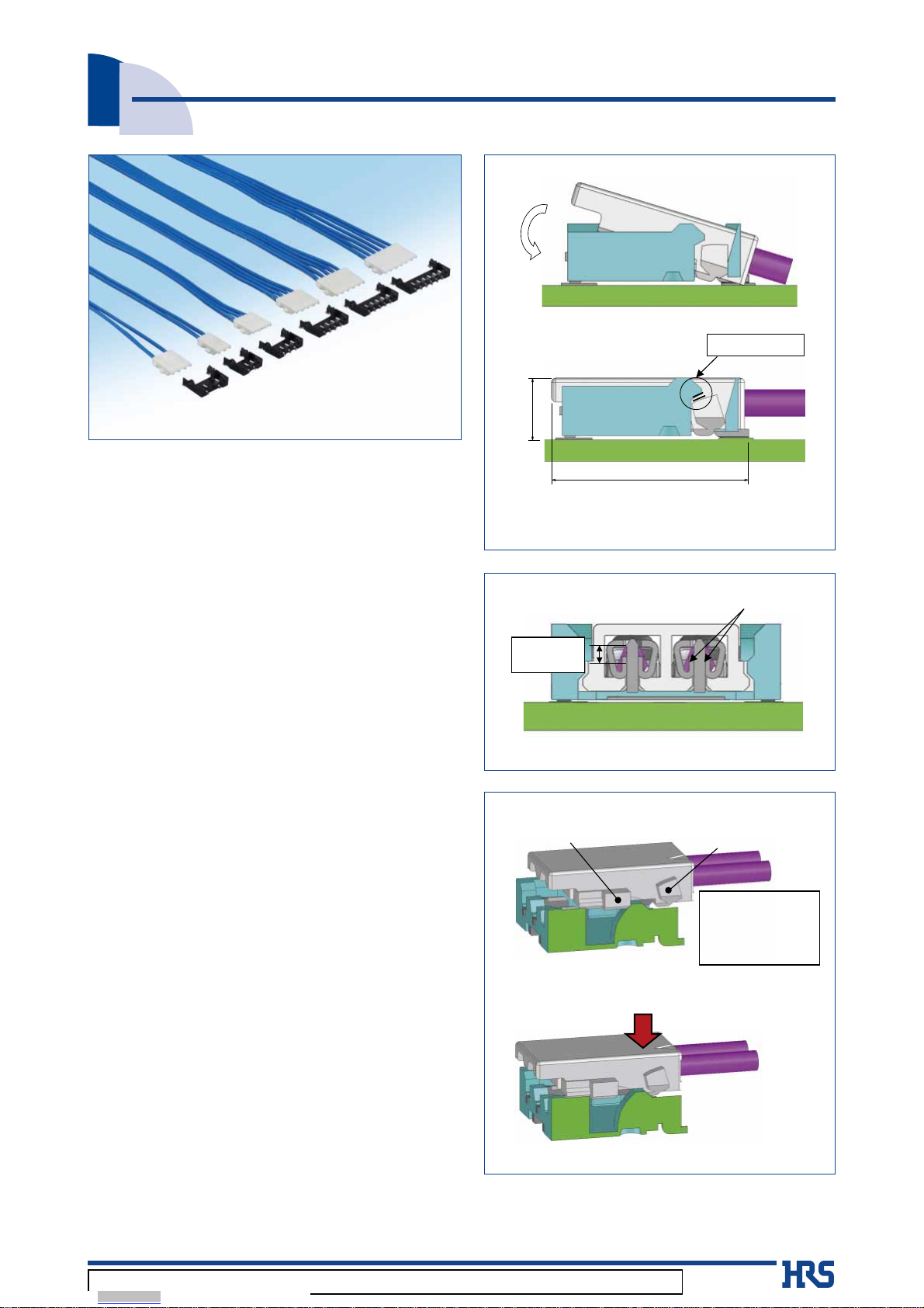
DF57 Series●Low Profile “Swing-Lock” Board to Wire Connector for Power
■Specifications
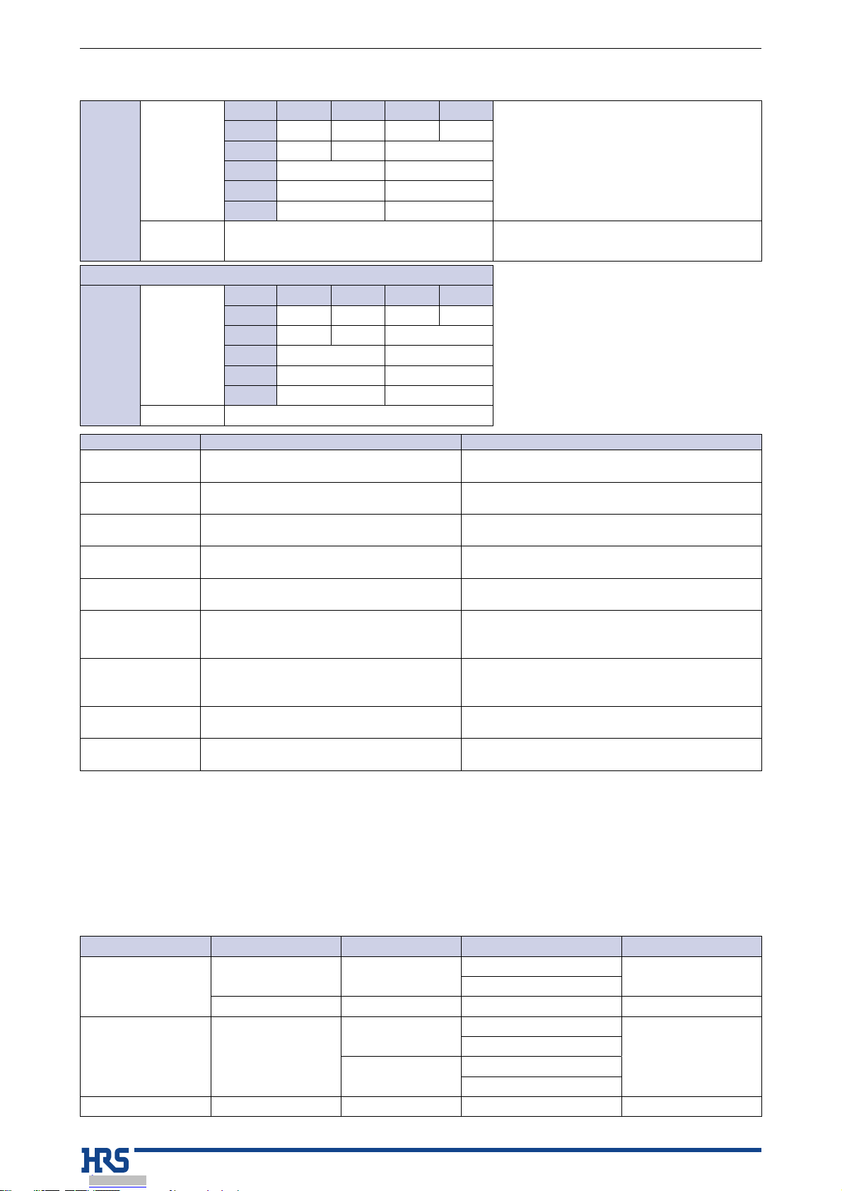
Rating
Current rating
(Note 1)
2pos. 3pos. 4pos. 5,6pos.
Operating temperature range -35ç to 85ç (Note 2)
Operating humidity range 20% to 80% (Note 3)
AWG#26
3.0A _ _ 1.5A
AWG#28
2.5A 2.0A 1.5A
AWG#30
1.5A 1.0A
AWG#32
1.0A 0.8A
AWG#34
0.8A 0.5A
Voltage rating
2 to 6 pos. : 50V AC/DC
2 pos. (Middle pin of 3 pos. is removed) : 100V AC/DC
Storage temperature range -10ç to 60ç (Note 4)
Storage humidity range 40% to 70% (Note 4)
UL, C-UL certified specifications
Rating
Current rating
(Note 1)
2pos. 3pos. 4pos. 5,6pos.
AWG#26
3.0A _ _ 1.5A
AWG#28
2.5A 2.0A 1.5A
AWG#30
1.5A 1.0A
AWG#32
1.0A 0.8A
AWG#34
0.8A 0.5A
Voltage rating 2 - 6 pos. : 29V AC/DC
Item Specification Conditions
1.Insulation
resistance 100Mø min. 100V DC
2.Withstanding
voltage
No flashover or insulation breakdown 500V AC / 1 minute
3.Contact
resistance 10mø max. 20mV max., at 1mA.
4.Vibration No electrical discontinuity of 1µs or longer
No damage, cracks or parts dislocation.
Frequency : 10 to 55Hz, single amplitude of 0.75mm,
10 cycles, 3 direction
5.Shock No electrical discontinuity of 1µs or longer
No damage, cracks or parts dislocation.
Acceleration of 490m/s2, 11ms duration, sine half-
wave, 3 cycles in each of the 3 axis
6.Humidity
Contact resistance : 20mø max.,
Insulation resistance : 500Mø min.
No damage, cracks or parts dislocation.
96 hours at 40 ±2ç, and humidity of 90 to 95%
7.Temperature
cycle
Contact resistance : 20mø max.,
Insulation resistance : 500Mø min.
No damage, cracks or parts dislocation.
-55°C →5 to 35°C →85°C →5 to 35°C
Times : 30 min. →2 min. to 3 min. →30 min. →2 min.
to 3 min. 5 cycles
8.Durability Contact resistance : 20mø max.,
No damage, cracks or parts dislocation. 30 cycles
9.Resistance to
soldering heat
No deformation of components affecting
performance
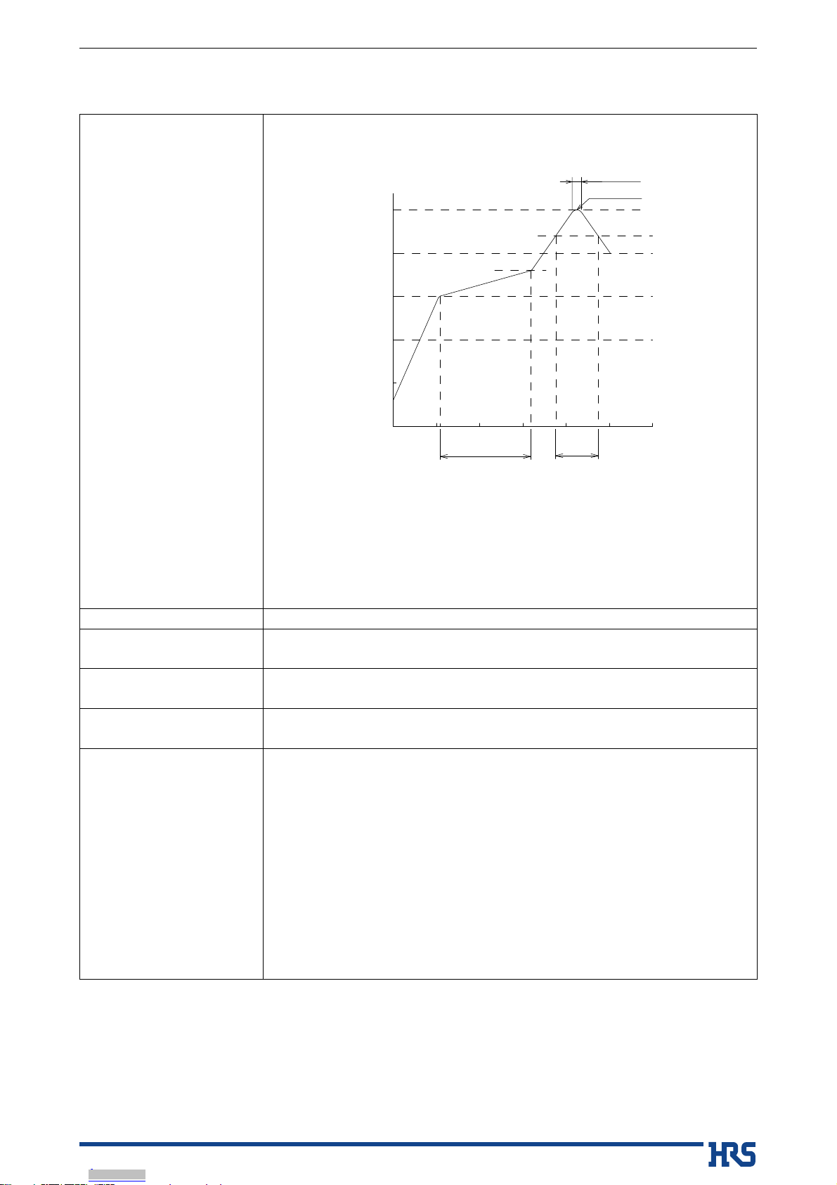
Reflow : At the recommended temperature profile
Manual soldering : 350°C for 3 seconds
Note 1 : This is the maximum current rating while all pins are powered or used as all power lines. When isolating power lines
into multiple circuits, current ratings may go above the stated current ratings. Please consult Hirose for specific details
before doing this.
Note 2 : Includes the temperature rise of power lines.
Note 3 : The connector should be completely dry. (no condensation present)
Note 4 : The term “storage” refers to the long-term storage condition of unused products before PCB mounting. The operating
temperature and humidity ranges are applied while in a non-energized state, while in transport or after PCB mounting.
■Material / Finish
Item Component Material Finish UL Flammability rating
Header Insulator LCP Black UL94V-0
Beige
Contact Brass Tin plating or gold plating ---------
Crimp socket Insulator
PBT White
UL94V-0
Black
LCP Beige
Black
Crimp contacts Contact Phosphor bronze Tin plating or gold plating ---------
Dec.1.2019Copyright2019HIROSEELECTRICCO.,LTD.AllRightsReserved.
Downloaded from Arrow.com.Downloaded from Arrow.com.


 User manual")