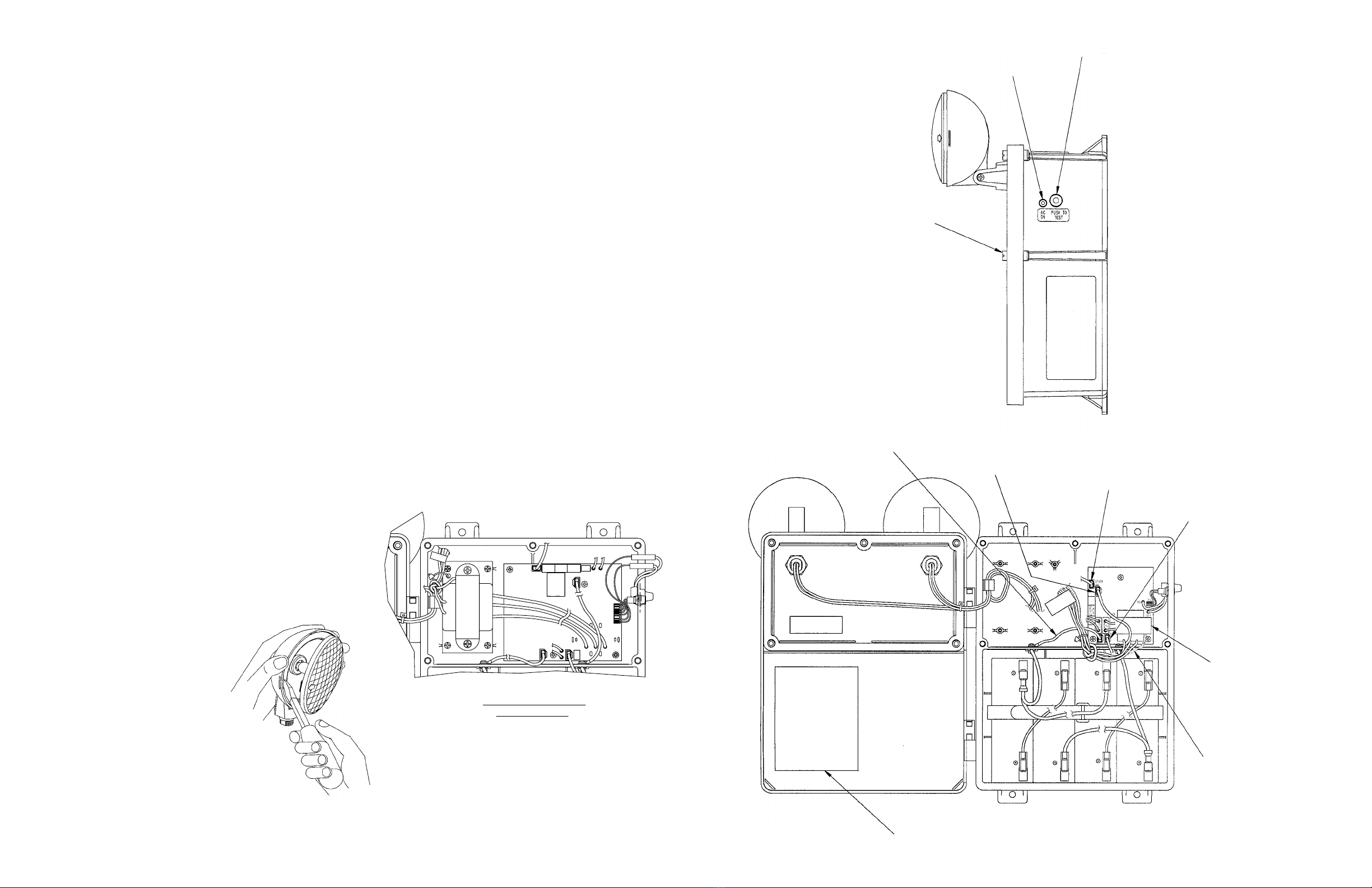
manuals.online logo
Brands
  1. Home
  2. •
  3. Brands
  4. •
  5. Hubbell
  6. •
  7. Lighting Equipment
  8. •
  9. Hubbell DUAL LITE N4X4 User manual

Hubbell DUAL LITE N4X4 User manual

N4X Series
High-Capacity Emergency Lighting Units
For Harsh-Environment Application
Installation Instructions
IMPORTANT SAFEGUARDS
When using electrical equipment, basic safety precautions should always be followed including the
following.
READ AND FOLLOW ALL SAFETY INSTRUCTIONS
1. Do not use outdoors.
2. Do not mount near heaters or hot surfaces.
3. Equipment should be mounted in locations and at heights where it will not readily be subject to
tampering by unauthorized personnel.
4. The use of accessory equipment not authorized by the manufacturer may cause an unsafe
condition.
Caution: Halogen cycle lamps may be used in this equipment. Halogen cycle lamps operate at
high temperatures. Do not store or place flammable materials near lamp. To avoid shattering:
Do not operate lamp in excess of rated voltage. Protect lamp against abrasion and scratches
and against liquids when operating. Dispose of lamp with care.
5. Do not use this equipment for other than its intended purpose.
6. Servicingofthisequipmentshouldbeperformedbyqualiedservicepersonnel.
SAVE THESE INSTRUCTIONS
Hubbell Lighting, Inc. Life Safety Products • www.dual-lite.com
Copyright©HubbellLighting,Inc.,AllRightsReserved•Specicationssubjecttochangewithoutnotice.•PrintedinU.S.A.
0603121 B 10/08
Total
Watts 6 Volt System Wire Gauge
on Wire
Run #12 #10 #8 #6
Max. Length of Wire Run (Feet)
6 94 150 238 379
7 81 129 204 325
8 70 112 179 284
10 56 90 143 227
12 44 70 112 178
14 40 64 102 162
16 33 53 84 134
18 30 47 75 119
20 28 45 71 114
21 27 43 68 108
24 24 38 60 95
25 21 34 54 86
30 19 30 48 76
35 15 25 39 63
40 13 21 33 53
48 11 17 28 44
50 11 17 27 43
75 7 11 18 29
100 5 8 14 21
125 4 7 11 17
150 3 5 9 14
175 3 5 8 12
200 2 4 6 10
225 2 4 6 10
250 2 3 5 9
VOLTAGE DROP TABLE
Total
Watts 12 Volt System Wire Gauge
on Wire
Run #12 #10 #8 #6
Max. Length of Wire Run (Feet)
6 378 600 955 1518
7 324 515 818 1301
8 283 450 716 1138
10 226 360 570 910
12 178 283 450 715
14 162 257 409 650
16 133 212 338 538
18 119 189 300 477
20 113 180 286 455
21 108 171 273 434
24 89 141 225 357
25 86 136 216 344
30 75 120 190 303
35 65 103 164 260
40 53 85 135 214
48 44 70 112 178
50 43 68 108 172
75 28 45 72 115
100 21 34 54 86
125 17 27 43 69
150 14 23 36 57
175 12 19 31 49
200 10 16 27 42
225 10 16 25 40
250 9 14 22 36
WARNING – This product contains chemicals known to the State of California to cause cancer, birth defects
and/or other reproductive harm. Thoroughly wash hands after installing, handling, cleaning, or otherwise
touching this product.
93020395
Cover Retaining
Screw
“AC-ON” LED
Test Button
GENERAL INSTRUCTIONS
This unit is designed for surface mounting on a wall or other sold surface (building support structure, column, etc.) using the
fourholesprovidedonthehousingmountingnges.Unitmustbemountedhighenoughtomaximizeilluminatedareaunder
anticipated conditions of use. Be sure to allow ample clearance for mounting and aiming the lighting heads.
Provideeachunitwithasingleunswitchedpowersupplyfroma120,277,or480VACbranchcircuitusedfornormallightinginthe
same area. The wiring should be permanent installation, using appropriate size wire.
Note: De-energize AC circuit to unit during initial installation, and during servicing or relamping operations.
PLACING THE UNIT IN SERVICE
1. Fasten enclosure to wall surface using appropriate hardware (not provided).
 2. Removetheve(5)coverretainingscrewsandopenunit.
3. Connect remote lamps (if used) to blue (+, fused) and yellow (–) leads (Fig. 1).
 4. Connect120,277,or480VACinputconnectionstotransformer(Fig.1).Connectgreenwiretobuildingground. 
Note: insulate the unused transformer lead to prevent potential shock hazard.
UNITS SUPPLIED WITH LEAD-CALCIUM BATTERIES
 5. Determineproperbatteryandwiringconguration(Seeinsidecoverlabelforbatteryandwirecongurations).
6. Connect positive (+, red) and negative (–, yellow) battery harness leads from printed circuit board to corresponding battery
  terminals(Seeinsidecoverlabelforbatteryandwirecongurations).
7. Check all wiring for loose or missing connections.
8. Replace cover. Tighten retaining screws. Adjust lighting heads to desired position.
 9. EnergizeunitwithACpower.Pressandholdthe“TEST”button(seeFig.1for“TEST”buttonlocation)toconrm  
  illuminationandproperaimingofemergencylamps.(“ACON”indicatorLEDshouldgooff).Releasethe“TEST”button; 
  emergencylampsshouldextinguish.Normaloperationbegins.
10. NormalOperation:withpowersupplied,“ACON”LEDindicatorisilluminatedandemergencylampsareoff.
ROUTINE TEST CYCLING
 1. Everythree(3)months:Iftherehasbeennopowerfailure,pressandholdthe“TEST”buttonforatleastthirty(30)seconds
  to conrmemergencylampoperation.Release“TEST”buttontoreturntobatterychargingmode.
 2. Onceayear:Performafullbatteryconditioningcyclebyde-energizingtheACcircuittowhichtheunitisconnected,and 
allow the unit to operate for ninety (90) minutes on battery power. Following successful test, energize AC circuit to begin
battery charging cycle.
REPLACING EMERGENCY LAMPS AND BATTERIES
General
1. De-energize the AC power supply to the unit.
2. Remove cover screws and open unit.
3. Disconnect positive (+, red) battery lead.
• Replacing Unit Emergency Lamp
1. Remove diffuser lens from
lamp housing by prying lens
adjacent to tab slot (see Fig.2)
2. Remove and replace lamp.
(refer to unit product label
  forspeciclamptype)
Instruction Label
Battery Location and Wire Connections
Yellow Negative (–)
Battery Lead Red Positive (+)
Battery Lead Remote DC Lamps
Positive (+) Lead with
“On-Board” Fuse
Remote DC Lamps
Negative (–) Lead
Transformer Ground
Wire (Green)
Transformer
120VAC – White and Black
277VAC – White and Red
Note: Potential Shock Hazard –
Insulate Unused Lead
Fig.2
Fig.1
• Replacing Unit Battery
1. Remove defective battery.
Recycle responsibly. Replace
with genuine Dual-Lite battery.
2. Placenewbatteryinenclosure.
Make connections following steps
outlined above.
3. Test unit.
LAMPS -
1
S1
L2-
4
3
2
8
7
6
5
H1H1
B+
L1+(F)
W/ABC 15
REPLACE
F1
K1
LAMPS +
L2+
L2-
L2+
B-
L1-
L1+(F)
B+
K1
REPLACE
W/ABC 15
F1
LAMPS +
H1
TRANSFORMER PRIMARY
WIRING FOR 480V
BLUE WIRES-480VAC
GREEN WIRE-GROUND
T1
AC INPUT

This manual suits for next models

1

Other Hubbell Lighting Equipment manuals

Hubbell KIM LIGHTING VRB1 User manual

Hubbell

Hubbell KIM LIGHTING VRB1 User manual

Hubbell Compass CU2SO User manual

Hubbell

Hubbell Compass CU2SO User manual

Hubbell ALFW-6LU-5KBZ Series User manual

Hubbell

Hubbell ALFW-6LU-5KBZ Series User manual

Hubbell Dual Lite CVEC15 User manual

Hubbell

Hubbell Dual Lite CVEC15 User manual

Hubbell NutriLED Series User manual

Hubbell

Hubbell NutriLED Series User manual

Hubbell Dual Lite EV Series Manual

Hubbell

Hubbell Dual Lite EV Series Manual

Hubbell KILLARK VSQ Series Owner's manual

Hubbell

Hubbell KILLARK VSQ Series Owner's manual

Hubbell Dual-Lite EV4D-02WAL Series Manual

Hubbell

Hubbell Dual-Lite EV4D-02WAL Series Manual

Hubbell Dual-Lite UFO-LP1 User manual

Hubbell

Hubbell Dual-Lite UFO-LP1 User manual

Hubbell SAVVANO User manual

Hubbell

Hubbell SAVVANO User manual

Hubbell KIM LIGHTING LIGHTVAULT LTV55 User manual

Hubbell

Hubbell KIM LIGHTING LIGHTVAULT LTV55 User manual

Hubbell homeSELECT RMS100 User manual

Hubbell

Hubbell homeSELECT RMS100 User manual

Hubbell Kim Lighting Lightvault LTV59 User manual

Hubbell

Hubbell Kim Lighting Lightvault LTV59 User manual

Hubbell VAPORTITE VBGL Series User manual

Hubbell

Hubbell VAPORTITE VBGL Series User manual

Hubbell Dual-Lite EVHC-BC Series Manual

Hubbell

Hubbell Dual-Lite EVHC-BC Series Manual

Hubbell PRS User manual

Hubbell

Hubbell PRS User manual

Hubbell Dual-Lite DYNC C1D2 Series User manual

Hubbell

Hubbell Dual-Lite DYNC C1D2 Series User manual

Hubbell KILLARK VEB Series Instruction Manual

Hubbell

Hubbell KILLARK VEB Series Instruction Manual

Hubbell ExpressLine Miniliter IV MHSY Series User manual

Hubbell

Hubbell ExpressLine Miniliter IV MHSY Series User manual

Hubbell VSLT-UP User manual

Hubbell

Hubbell VSLT-UP User manual

Hubbell Prescolite LBSLEDA User manual

Hubbell

Hubbell Prescolite LBSLEDA User manual

Hubbell Laredo LMC User manual

Hubbell

Hubbell Laredo LMC User manual

Hubbell DUAL LITE LN4X Series Owner's manual

Hubbell

Hubbell DUAL LITE LN4X Series Owner's manual

Hubbell Laredo User manual

Hubbell

Hubbell Laredo User manual

Popular Lighting Equipment manuals by other brands

Reely RE-5631027 operating instructions

Reely

Reely RE-5631027 operating instructions

STL Z-6 TIR STD instruction manual

STL

STL Z-6 TIR STD instruction manual

Task Lighting Sempria LED Q Series installation instructions

Task Lighting

Task Lighting Sempria LED Q Series installation instructions

C Luce 04 LED LUXEON M manual

C Luce

C Luce 04 LED LUXEON M manual

THORLABS DC3100 Series Operation manual

THORLABS

THORLABS DC3100 Series Operation manual

Larson Electronics EPL-WPLED-100W-RT-PSC instruction manual

Larson Electronics

Larson Electronics EPL-WPLED-100W-RT-PSC instruction manual

OMS Double Light Series manual

OMS

OMS Double Light Series manual

Ignition Stagepix Line 100 IP user manual

Ignition

Ignition Stagepix Line 100 IP user manual

HORNEET SA066 Instruction for operation and maintenance

HORNEET

HORNEET SA066 Instruction for operation and maintenance

Luminaire led LVP1212 LED Series installation guide

Luminaire led

Luminaire led LVP1212 LED Series installation guide

MELINERA 288593 Operation and safety notes

MELINERA

MELINERA 288593 Operation and safety notes

WE-EF XRY300 LED Series Installation and maintenance instructions

WE-EF

WE-EF XRY300 LED Series Installation and maintenance instructions

RPS Studio RS-SP600 instructions

RPS Studio

RPS Studio RS-SP600 instructions

ARRI EB 575/800 operating instructions

ARRI

ARRI EB 575/800 operating instructions

Ikan Lightstar LSKT-001 quick start guide

Ikan

Ikan Lightstar LSKT-001 quick start guide

ADJ Flat Par CWWW9 User instructions

ADJ

ADJ Flat Par CWWW9 User instructions

Ametrix ADY080112 installation instructions

Ametrix

Ametrix ADY080112 installation instructions

Hensel C-Light 1000 user manual

Hensel

Hensel C-Light 1000 user manual

manuals.online logo
manuals.online logoBrands
  • About & Mission
  • Contact us
  • Privacy Policy
  • Terms and Conditions

Copyright 2025 Manuals.Online. All Rights Reserved.