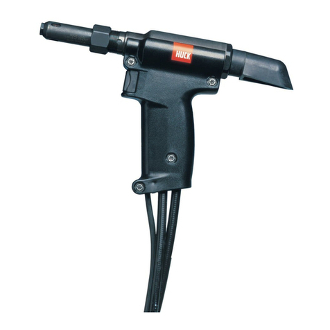
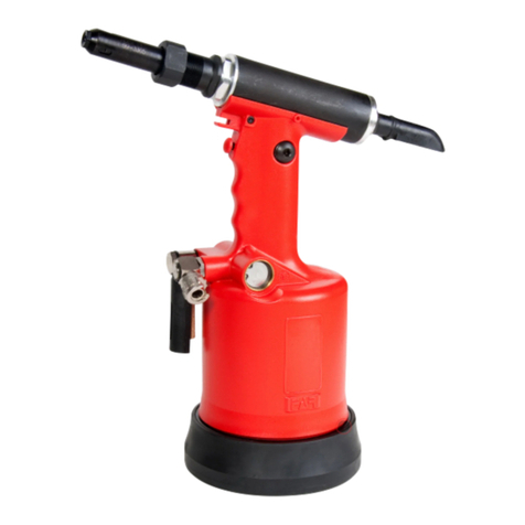
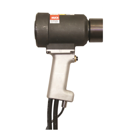
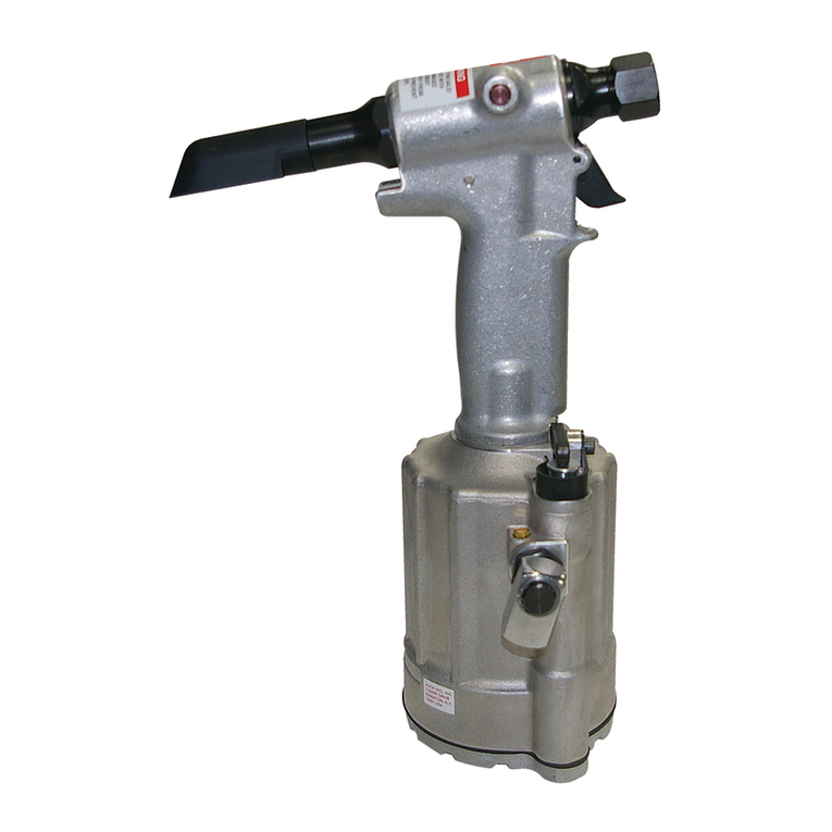
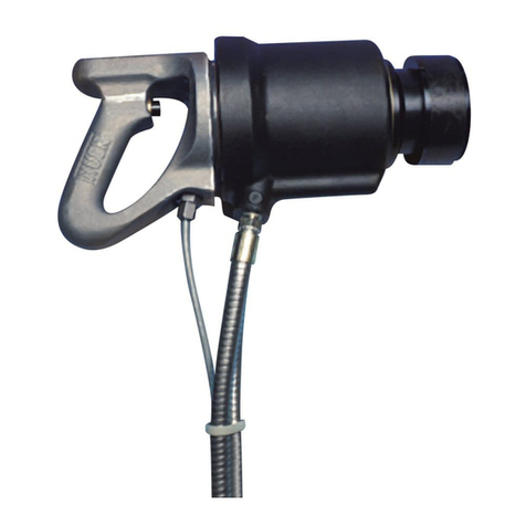
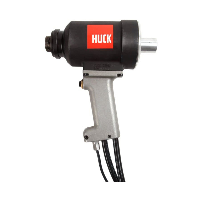
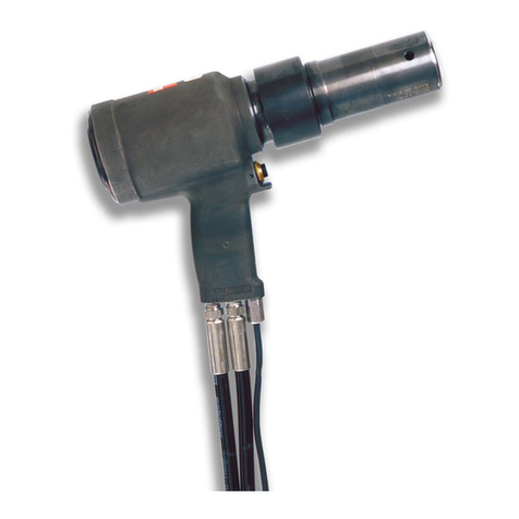
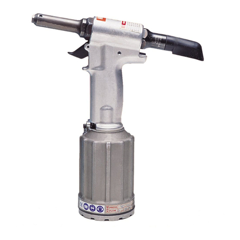
Huck ALCOA 212 User manual

11-09-2009
HK838
INSTRUCTION MANUAL
212
PNEUDRAULIC INSTALLATION TOOL


January 29, 2014
PB618
THREADLOCKER RECOMMENDATION
Loctite®243 THREADLOCKER
TO REPLACE Vibra-Tite®IN
HUCK PNEUDRAULIC INSTALLATION TOOLS
Page 1 of 1
In order to ensure ease of assembly of back caps
and air pistons, among other components of HUCK
installation equipment, it is recommended that
wherever Vibra-Tite
®
has been mentioned in a HUCK
instruction manual or product bulletin procedure, the
product Loctite
®
243 Threadlocker be used instead.
This oil-tolerant, removable, medium-strength blue
threadlocker is designed for locking and sealing
threaded components. It can be applied smoothly
and will now be the HUCK recommended standard
for these applications. For best results, follow
manufacturer’s recommendations for use.
Loctite
®
243 Threadlocker is available for purchase
from HUCK in a .5 mL tube as part number 508567.
Locite is a registered trademark of Henkel Corporation, U.S.A.
Vibra-Tite is a registered trademark of ND Industries, Inc. USA.
For more informaƟon or to order, please contact your local distributor or call direct:
Alcoa Fastening Systems
1 Corporate Drive
Kingston, NY 12401
800-278-4825
PKG: 8452
GRP: 01 through 12, 15 through 19, & 21-22

This page is intentionally blank.

212 Series Tooling Alcoa Fastening Systems
3
SAFETY
This instruction manual must be read with particular
attention to the following safety guide lines, by any
person servicing or operating this tool.
1. Safety Glossary
WARNINGS - Must be understood
to avoid severe personal injury.
CAUTIONS - show conditions that will dam-
age equipment and or structure.
Notes - are reminders of required proce-
dures.
Bold, Italic type and underlining - empha-
sizes a specific instruction.
2. Huck equipment must be maintained in a safe
working condition at all times and inspected on a
regular basis for damage or wear. Any repair
should be done by a qualified repairman trained
on Huck procedures.
3. Repairman and Operator must read manual prior
to using equipment and understand any Warning
and Caution stickers/labels supplied with equip-
ment before connecting equipment to any pri-
mary power supply. As applicable, each of the
sections in this manual have specific safety and
other information.
4. See MSDS Specifications before servicing the
tool. MSDS Specifications are available from
you Huck representative or on-line at
www.huck.com. Click on Installation Systems
Division.
5. When repairing or operating Huck installation
equipment, always wear approved eye protec-
tion. Where applicable, refer to ANSI Z87.1 -
1989
6. Disconnect primary power source before doing
maintenance on Huck equipment.
7. If any equipment shows signs of damage, wear,
or leakage, do not connect it to the primary
power supply.
8. Make sure proper power source is used at all
times.
9. Never remove any safety guards or pintail
deflector.
10. Never install a fastener in free air. Personal
injury from fastener ejecting may occur.
11. When using an offset nose always clear spent
pintail out of nose assembly before installing the
next fastener.
12. If there is a pinch point between trigger and
work piece use remote trigger. (Remote trig-
gers are available for all tooling).
13. Do not abuse tool by dropping or using it as a
hammer. Never use hydraulic or air lines as a
handle. Reasonable care of installation tools by
operators is an important factor in maintaining
tool efficiency, eliminating downtime, and in pre-
venting an accident which may cause severe
personal injury.
14. Never place hands between nose assembly and
work piece.
15. Tools with ejector rods should never be cycled
with out nose assembly installed.
16. When two piece lock bolts are being used
always make sure the collar orientation is cor-
rect. See fastener data sheet of correct posi-
tioning.
!
Product complies with requirements
set forth by the relevant European
directives.
Read manual prior to using
equipment.
Eye protection required while
using this equipment.
Hearing protection required while
using this equipment.

212 Series Tooling Alcoa Fastening Systems
4
Section Page
Safety Guidelines . . . . . . . . . . . . . . . . . . . . . . . . . . . . . . . . . . . . . . . . . . . . . . . . . 3
Description . . . . . . . . . . . . . . . . . . . . . . . . . . . . . . . . . . . . . . . . . . . . . . . . . . . . . .5
Specifications . . . . . . . . . . . . . . . . . . . . . . . . . . . . . . . . . . . . . . . . . . . . . . . . . . . .5
Principle of Operation . . . . . . . . . . . . . . . . . . . . . . . . . . . . . . . . . . . . . . . . . . . . . .7
Preparation for Use . . . . . . . . . . . . . . . . . . . . . . . . . . . . . . . . . . . . . . . . . . . . . . . .8
Operating Instructions . . . . . . . . . . . . . . . . . . . . . . . . . . . . . . . . . . . . . . . . . . . . . .9
Maintenance . . . . . . . . . . . . . . . . . . . . . . . . . . . . . . . . . . . . . . . . . . . . . . . .10 & 11
Good Service Practices . . . . . . . . . . . . . . . . . . . . . . . . . . . . . . . . . . . . . . . . .10
Preventive Maintenance . . . . . . . . . . . . . . . . . . . . . . . . . . . . . . . . . . . . . . . .11
Tool Maintenance . . . . . . . . . . . . . . . . . . . . . . . . . . . . . . . . . . . . . . . . . . . . . .11
Standard tools . . . . . . . . . . . . . . . . . . . . . . . . . . . . . . . . . . . . . . . . . . . . . . . .11
Nose Assembly Maintenance . . . . . . . . . . . . . . . . . . . . . . . . . . . . . . . . . . . . .11
Filling and Bleeding Procedure . . . . . . . . . . . . . . . . . . . . . . . . . . . . . . . . .12 & 14
How To Measure Stroke . . . . . . . . . . . . . . . . . . . . . . . . . . . . . . . . . . . . . . . . . . .15
Troubleshooting . . . . . . . . . . . . . . . . . . . . . . . . . . . . . . . . . . . . . . . . . . . . . . . . . .16
Spare Parts and Service Kit . . . . . . . . . . . . . . . . . . . . . . . . . . . . . . . . . . . . . . . .16
Disassembly . . . . . . . . . . . . . . . . . . . . . . . . . . . . . . . . . . . . . . . . . . . . . . . .17 & 18
Assembly . . . . . . . . . . . . . . . . . . . . . . . . . . . . . . . . . . . . . . . . . . . . . . . . . .19 & 20
Parts List . . . . . . . . . . . . . . . . . . . . . . . . . . . . . . . . . . . . . . . . . . . . . . . . . . .27 - 29
Notes and Specifications for Standard Parts . . . . . . . . . . . . . . . . . . . . . . . . . . .30
Accessories . . . . . . . . . . . . . . . . . . . . . . . . . . . . . . . . . . . . . . . . . . . . . . . . . . . . .30
CONTENTS

212 Series Tooling Alcoa Fastening Systems
5
The Model 212 is a lightweight, high speed pro-
duction tool designed to install a wide range of
Huck blind fasteners, and HUCKBOLT®
Fasteners, including 3/16" and 1/4" diameter
MAGNA-GRIP® Fasteners and MAGNA-LOK®
Fasteners.
Pulling action of the pull piston is provided by a
pneumatic-hydraulic (pneudraulic) intensifier
system powered by 90-100 psi air pressure. The
air inlet is equipped with a connector with 1/4-18
female pipe threads to accept your air hose or
quick connect fitting. The piston return stroke is
spring actuated.
A nose assembly is required for each fastener
type and size. Nose assemblies must be
ordered separately.
Weight 8.50 pounds (3.0 kg.)
Length of Head (1) 9.00 inches (228 mm)
Width of Head (1) 1.44 inches (37 mm)
Edge to Centerline 72 inches (18 mm)
Cylinder Diameter 4.63 inches (118 mm)
Height13.00 inches (330 mm)
Air Pressure 90-100 psi (620-690 kPa)
Air Consumption* 6 CFM (0.003 m 3/s)
Minimum Stroke .812 (20.6 mm)
Minimum Pull Force @90 psi 5,200 psi (35,535 kPa)
* (based on 30 fastener installations per minute.)
(1) Weight and length of tool does not include nose assembly.
Fasteners installed: See SELECTION CHARTS or your Huck representative.
Hydraulic Fluid: Automatic Transmission fluid, *DEXRON II, III or equivalent.
DEXRON II & III are registered trademarks of General Motors Corporation.
DESCRIPTION
SPECIFICATIONS

212 Series Tooling Alcoa Fastening Systems
6
Fig. 1
Outline Drawing

212 Series Tooling Alcoa Fastening Systems
7
When tool is connected to air supply, air pres-
sure holds throttle valve in up position - - air
pressure is directed to top of piston keeping it
down. Depressing trigger moves throttle valve to
down position - - air is directed to bottom of
piston moving it upward. Air from above piston
is exhausted downward through throttle valve
and exits muffler at bottom of tool. Air piston rod
is a hydraulic piston - - pressurized fluid is
forced into head moving pull piston rearward.
When fastener installation is completed, trigger
is released. Air pressure causes throttle valve to
return to its up position, reversing airflow. Air
piston and rod move down to their starting posi-
tion - - air is exhausted from below piston
through muffler at bottom of tool. As rod moves
downward and hydraulic pressure is released
from pull piston, a spring behind pull piston
returns it to its starting position.
PRINCIPLE OF OPERATION
Fig. 2
Sectional View

Tool is shipped with a plastic plug in air inlet con-
nector. This connector has 1/4-18 female pipe
threads to accept hose fining. Quick connect fit-
tings and 1/4 inch inside diameter air hose are
recommended. An air supply of 90 - 100 psi
capable of 6 CFM must be available. The air
supply should be equipped with a filter-regulator-
lubricator unit.
1. Remove plastic plug from air inlet connector
and drop in a few drops of automatic trans-
mission fluid, DEXRON II, III or equivalent.
2. Screw whip air hose and quick-connect
fitting into air inlet connector.
3. Set air pressure on regulator to 90 psi.
4. Connect air hose to tool.
5. Cycle tool a few times by depressing and
releasing trigger.
6. Disconnect air hose from tool.
7. Remove retaining nut.
8. Use pintail tube(s) as specified on NOSE
ASSEMBLY DATA SHEET and/or FIGURE 2.
9. Select nose assembly from SELECTION
CHART for fastener to be installed, or see
Huck representative. Attach nose assembly
to tool following applicable NOSE ASSEMBLY
DATA SHEET.
(1) Quick connect fittings and air hoses are not
available from Huck.
212 Series Tooling Alcoa Fastening Systems
8
PREPARATION FOR USE
!
WARNINGS
Do not pull on a pin without a collar. If
a pin is pulled without a collar, pin will
eject forcibly when pintail separates.
Severe personal injury may result.
If deflectors are removed or damaged,
separated pintails may eject forcibly
from rear of tool. Severe personal injury
may result.
To avoid pinch points, be sure there is
adequate clearance for tool and opera-
tor’s hands before proceeding. Tool mov-
ing toward structure may cause severe
personal injury if clearance is limited.

212 Series Tooling Alcoa Fastening Systems
9
OPERATING INSTRUCTIONS
PLEASE NOTE
Failure to understand WARNINGS may cause
severe personal injury and failure to understand
CAUTIONS may cause damage to structure and
tool.
HUCKBOLT® Fastener Installation:
CAUTION
Remove excess gap from between the
sheets. This permits enough pintail to
emerge from collar for ALL jaw teeth to
engage with pintail - - if ALL teeth do not
engage properly, jaws will be damaged.
Place pin in workpiece and place collar over pin - -
See WARNING. (If Collar has only one tapered
end, that end MUST be out toward tool - - not next
to sheet.) Hold pin and push nose assembly onto
pin protruding through collar until nose anvil touches
collar. Depress trigger - - hold trigger depressed
until collar is swaged and pintail breaks. Release
trigger. Tool will go into its return stroke. Tool/nose
are ready for next installation cycle.
Blind Fastener Installation:
CAUTION
Remove excess gap from between the sheets to
permit correct fastener installation and prevent
jaw damage. ALL jaw teeth must engage pintail
to avoid damaging teeth.
Fastener may be placed in workpiece or In end of
nose assembly - - see WARNING. In either case,
tool/nose must be held against work and at right
angles to it. Depress trigger - - hold trigger
depressed until fastener is installed and pintail
breaks. Release trigger. Tool will go into its return
stroke. Tool/nose are ready for next installation
cycle.
CAUTIONS
BOM® blind fasteners jam in nose assembly if
pulled when not in workpiece.
To avoid structural and tool damage, be sure
enough clearance is allowed for nose assembly
at full stroke.
Do not abuse tool by dropping it, using it as a
hammer or otherwise causing unnecessary
wear and tear.
Reasonable care of tools by operators is an
important factor in maintaining efficiency and
reducing downtime.
WARNINGS
To avoid severe personal injury: Wear
approved eye and ear protection. Be sure
of adequate clearance for operator’s
hands before proceeding with fastener
installation. Be sure that pintail deflector
is on tool and directed away from all per-
sonnel.
!
!
!
WARNING
Do not pull on a pin without placing
fastener/collar in a workpiece, and
also, collar chamfer MUST be out
toward tool - - these conditions cause
pin to eject with great velocity and
force when the pintail breaks off or
teeth/grooves strip. This may cause
severe personal injury.
WARNING
Do not pull on a pin without placing
fastener in a workpiece - - fastener will
eject from front with velocity and force
when pintail breaks off or teeth/grooves
strip - - this may cause severe personal
injury.

212 Series Tooling Alcoa Fastening Systems
10
MAINTENANCE
Good Service Practices
The efficiency and life of any tool depends upon
proper maintenance and good service practices.
Tool should be serviced by personnel who are
thoroughly familiar with it and how it operates.
A clean, well-lighted area should be available for
servicing the tool. Special care must be taken to
prevent contamination of pneumatic and
hydraulic systems. Proper hand tools and soft
materials to protect tools must be available. Only
standard hand tools, brass drift and wood block
are required. Vise with soft jaws should be avail-
able. See Table 2 for tools available from
Huck.
ALWAYS REPLACE ALL SEALS AND BACK-
UP RINGS WHEN TOOL IS DISASSEMBLED
FOR ANY REASON.
All parts must be handled carefully and exam-
ined for damage and/or wear. Components
should be disassembled and assembled in
straight line without bonding, cocking or undue
force. DISASSEMBLY and ASSEMBLY proce-
dures outlined in this manual should be followed.
Rub SLIC-TITE TEFLON* thread compound, or
equivalent, on pipe plug threads and quick con-
nect fitting. CAUTION: Do not use Teflon tape
on pipe threads. Pipe threads may cause tape
to shred, resulting in tool malfunction. SLIC-
TITE, 503237, is available in stick form from
Huck. Smear LUBRIPLATE 130AA*, or equiva-
lent, on seals (O-rings etc.) and mating surfaces
to aid assembly and to prevent damage to seals.
LUBRIPLATE 13OAA, 502723, is available in a
tube from Huck.
Use VIBRA-TITE* on Gland (29) threads.
VIBRA-TITE, 505125, is available from Huck.
Follow directions on bottle.
Apply LOCTITE Adhesive/Sealant to Nut,
505420. LOCTITE, 503657, - - in a tube - - is
available from Huck. Service Kit, 212KIT,
includes perishable parts and should be kept on
hand. Other components, as experience dictates,
should also be readily available for replace-
ments.
LUBRIPLATE is a trademark of Fiske Brothers Refining Co.
TEFLON is a trademark oF E. I. DuPont de Nemours & Co.
VIBRA-TITE is a trademark of the Oakland Corporation.
LOCTITE is a trademark of Loctite Corp.

212 Series Tooling Alcoa Fastening Systems
11
MAINTENANCE (CONT.)
Preventive Maintenance
Tool Maintenance
The 212 requires a minimum amount of mainte-
nance. Regular inspection and correction of
minor problems will keep the tool operating effi-
ciently and prevent downtime.
If a filter-regulator-lubricator unit is not being
used in the air supply:
(1) Remove hose fitting from air inlet connector
and drop in a few drops of automatic trans-
mission fluid or light oil.
(2) Blow out air line to remove dirt and water
before connecting air hose to tool.
At regular intervals, depending upon use,
replace all seals in tool. Service Kits should be
kept on hand. (See SPARE PARTS AND SERV-
ICE KIT; NOTES.) Inspect both hydraulic
pistons, and their piston rods for scored
surfaces, excessive wear or damage, and
replace as necessary.
CAUTION: Always replace seals and back-up
rings when tool is disassembled for any rea-
son.
Nose Assembly Maintenance
To extend jaw life: Disassemble nose assembly
periodically; clean and inspect components - -
use a pick to clean jaw grooves. CAUTION:
Wash pads in mineral spirits or isopropyl
alcohol ONLY. Dry O-rings; urethane jaw
assemblies IMMEDIATELY after cleaning as pro-
longed contact with solvent causes swelling - -
dry other parts.
In nose assemblies without UNITIZEDTM jaws,
dip nose assembly in mineral spirits, isopropyl
alcohol, or other suitable solvent, to clean jaws
and wash away metal chips and dirt. If more
thorough cleaning or maintenance is necessary,
disassemble nose assembly. Use pick to remove
particles packed in jaw grooves. Reassemble per
instructions on applicable NOSE ASSEMBLY
DATA SHEET.
STANDARD TOOLS AVAILABLE FROM HUCK
PART DESCRIPTION REF. P/N
502294 Hex Key, 1/8 across flats 45 504127
505898 Hex Key, 7116 across flats 35 116136
503904 Screw Driver 4 104293

212 Series Tooling Alcoa Fastening Systems
12
Equipment Required:
• Shop airline with 90- 100 psi max.
• Air regulator
• Fill bottle, 120337, (supplied with tool).
• Large flat blade screwdriver
• Nose assembly or optional stall nut
• Fasteners
• Optional stall nut, 124090
Stall nut is used to load tool during bleeding
and for measuring stroke.
Preparation:
1. Install air regulator in airline and set
pressure to 20-40 psi.
2. Fill bleed bottle almost full of DEXRON II or
III - - ATF (automatic transmission fluid) - -
see FIGURE 3.
Procedure to Fill Empty Tool (new or rebuilt)
- - as Applicable:
1. Attach the tool air source momentarily to
seat air piston at bottom of cylinder -
- disconnect tool. With fillport facing up, lay
tool on its side.
2. With a screwdriver, remove bleed plug from
fillport.
FILLING AND BLEEDING PROCEDURE
Fig. 3
Fig. 3.1
WARNING
Air pressure MUST be set to 20 - 40
psi to prevent possible injurious high
pressure spray. Never cycle tool with-
out bleed plug tightened, fill bottle
tightened in tool, or filIport held over
a receptacle (see FIGURE 3.1). When
not properly contained any fluid pres-
ent in tool will spray out. Severe
injury may result.
!
3. Screw fill bottle into fillport in the head.
4. Set airline pressure to 20 - 40 psi and
connect airline to tool.

212 Series Tooling Alcoa Fastening Systems
13
Fig. 3.2
Fig. 3.3
FILLING AND BLEEDING PROCEDURE (CONT.)
5. Stand tool upright on bench. While triggering
tool slowly (20 - 30 cycles), bend fill bottle at
right angles to tool- - see FIGURE 3.2. Air
bubbles will emerge from tool. When bubbles
stop, cycling may be discontinued.
6. When trigger is released, pull piston returns
to idle position (full forward). Disconnect tool
from airline.
7. Lay tool on its side. Remove fill bottle. Top
off fluid in fillport. Install bleed plug and
tighten.
8. Connect airline to tool. There is a choice of
two procedures for measuring the stroke - -
with and without a stall-nut - - see appropri-
ate section and follow the selected procedure.
If stroke is less than specified, remove bleed
plug and top off fluid. Reinstall bleed plug.
9. Increase air pressure to specification. Install
two fasteners to check function and installation
in a single stroke, or cycle tool with stall-nut
fully threaded onto piston to load up tool.
Measure stroke again. Remove plug and top
off fluid. Reinstall plug and cycle again - -
measure again. Continue this process until
stroke meets minimum requirements,
Bleed Procedure for Partially Filled Tool in
Field Use - - as Applicable:
1. Disconnect tool from airline. With fillport
facing up, lay tool on its side.
2. Remove bleed plug from bleed port.
3. Hold tool over suitable container with fillport
facing into container.
4. Connect tool to airline. cycle tool several times
to drain the old fluid, air and foam.
5. Screw fill bottle into fillport.
6. See warning above. With air pressure set at 20
- 40 psi, connect airline to tool
WARNING
Air pressure MUST be set to 20- 40 psi
to prevent possible injurious high pres-
sure spray. Never cycle tool without
bleed plug tightened, fill bottle tightened
in the tool, or the fillport held over a
receptacle (see FIGURE 3.3). When not
properly contained any fluid present in
tool will spray out. Severe injury may
result.
!

212 Series Tooling Alcoa Fastening Systems
14
Fig. 3.4
FILLING AND BLEEDING PROCEDURE (CONT.)
7. Stand tool upright on bench. While
actuating the trigger slowly (20 - 30
cycles), bend fill bottle at right angles to
tool - - see FIGURE 3.4. Observe that air
bubbles emerge from tool. When bubbles
are no longer observed, cycling may be
discontinued.
8. When trigger is released, pull piston
returns to idle position (full forward).
Disconnect tool from airline with piston
full forward.
9. Lay tool on its side. Remove fill bottle.
Top off fluid in fillport. Install bleed plug
and tighten with screwdriver.
10.Connect airline to tool. There is a choice
of two procedures for measuring the
stroke - - with and without a stall-nut - -
see appropriate section and follow the
selected procedure. If stroke is less than
specified, remove bleed plug and top off
fluid. Reinstall bleed plug.
11. Install two fasteners to check function
and installation in a single stroke, or
cycle tool with stall nut fully threaded
onto piston. Measure stroke again.
Remove plug and top off fluid. Reinstall
plug and cycle again - - measure again.
Continue this process until stroke meets
minimum requirements.

212 Series Tooling Alcoa Fastening Systems
15
Fig. 4.1
Fig. 4
To measure stroke of tool with stall-
nut threaded onto piston:
1. Disconnect tool from airline -- remove nose
from tool.
2 With piston fully forward (end of RETURN
stroke), bottom the stall-nut on piston. Back
stall-nut off five (5) turns.
3. Cycle tool and hold trigger depressed - -
this keeps piston fully to the rear and at end
of PULL stroke. Thread stall-nut back onto
piston until it contacts stop.
4. Release trigger. Stall-nut wilI move forward
with piston. See FIGURE 4 and measure “X”
dimension. This is the tools stroke.
5. If stroke is less than .812, refer to appropri-
ate previous section. Follow filling and top-
ping off instructions
To measure stroke of tool without
stall-nut:
1. Disconnect tool from airline - - remove nose
from tool.
2. With piston fully forward (end of RETURN
stroke), measure and record “X” dimension - -
see FIGURE 4.1.
3. Hold trigger depressed. Piston is now fully to
the rear and at end of PULL stroke. Measure
and record “Y” dimension.
4. Subtract “X” dimension from “Y” dimension.
5. If stroke is less than .812, refer to appropriate
previous section. Follow filling and topping off
instructions.
HOW TO MEASURE STROKE

212 Series Tooling Alcoa Fastening Systems
16
TROUBLESHOOTING
Always check out the simplest possible cause of
a malfunction first. For example, an air hose not
connected. Then proceed logically, eliminating
each possible cause until the defective part is
located. Where possible, substitute known good
parts for suspected bad parts. Use this page as
an aid in locating and correcting malfunction:
SPARE PARTS AND SERVICE KIT
The quantity of spare parts that should be kept
on hand varies with application and number of
tools in service. Service parts kit containing per-
ishable parts such as O-rings, back-up rings,
etc., should be kept on hand. Parts included in
SERVICE KIT 212KIT, are indicated by asterisks
(*) in PARTS LIST.
1. Tool fails to operate when trigger is depressed.
a. Throttle valve O-ring (53) or O-ring (54) worn or damaged.
b. Broken throttle cable.
2. Tool does not complete fastener installation or break pintail.
a. Air pressure too low. Set to 90 psi.
b. Hydraulic fluid low causing short stroke.
c. Air piston QUAD Ring (40) worn or damaged.
d. Air in hydraulic system (see FILLING AND BLEEDING TOOL).
3. Hydraulic fluid exhausts with air.
a. Worn or damaged O-ring (37) and Back-up Ring (36) or
O-ring (30); O-ring (33) and Back-up Ring (34); POLY-SEAL
(32) or QUAD Ring (31).
4. Hydraulic fluid leaks at Hydraulic Cylinder Head (14).
a. Worn or damaged Pull Piston Rod POLY-SEAL (7).
5. Hydraulic fluid leaks at Pull Piston Rod (6).
a. Worn or damaged Pull Piston Rod POLY-SEAL (7).
6. Pull Piston (6) will not return.
a. Broken or weak Spring (13).
7. Air leaks at air Cylinder Head (43).
a. O-ring (44) damaged.

212 Series Tooling Alcoa Fastening Systems
17
DISASSEMBLY
See applicable illustrations.
For parts identification, refer to applicable fig-
ures, tables and parts lists. Numbers in paren-
theses ( ) are reference numbers shown in man-
ual.
The following procedure is for complete disas-
sembly of tool. Disassemble ONLY those compo-
nents necessary to replace damaged or worn O-
rings, QUAD rings, back-up rings and other com-
ponents.
1. Disconnect tool from air source.
2. Unscrew Retaining Nut (2) and remove Nose
Assembly. Remove Pintail Tube (1).
3. Unscrew Bleed Plug (4) including O-ring (5)
from top of Handle/Head (3). Turn tool over
and allow fluid to drain into container - - tool
may be cycled to clear tool more completely.
Discard fluid.
4. Pull Deflector (17) off End Cap (14).
5. Using wrench, unscrew End Cap (14). Slide
out Spring (13)
6. CAUTION - - to prevent damage to Piston
Seals and Gland Seals when removing
them - - install OPTIONAL POLY-SEAL
Insertion Tool (121694-212).
Thread POLY-SEAL Insertion Tool, 121694-
212, into head/handle.
7. Slide Spacer, 123112-2, over piston rod.
8. Thread Piston Assembly Tool, 123111-2, onto
piston.
9. Push complete piston from front using brass
drift - -allow clearance for
piston as it exits tool.
10.Remove Piston Assembly Tool, Spacer, and
POLY-SEAL Insertion Tool.
11.Inspect Piston (6) for wear, scoring or dam-
age. Replace when necessary. Remove
Retaining Ring (64) and Washer (63). Hold
tool securely with bottom up.
12.Remove three Button Head Screws (51) with
1/8 hex key. Remove Muffler End Cap (50)
and Bottom Exhaust Gasket (48). Remove
Muffler (47) with O-ring (46) from end cap.
13.Remove Retaining Ring (45) from Cylinder
(24).
14. Screw Button Head Screws (51) back into
Cylinder Head (43). Carefully pull on
screws to remove Cylinder Head (43).
!
!
WARNING
Be sure air hose is disconnected before
cleaning or when replacing worn or
damaged tool components. Tool may
be actuated if not disconnected and
cylinder is under pressure. Severe
personal injury may result.
WARNING
Never cycle tool without bleed plug
installed and tightened, the bottle
installed and tightened in tool head, or
the fillport held over a suitable con-
tainer. If fluid is present it will spray
out of tool. Severe eye injury may
result. Air pressure MUST be set at 20
- 40 psi.

212 Series Tooling Alcoa Fastening Systems
18
DISASSEMBLY (CONT.)
15.Screw 1/4-20 UNC screws into Piston (39).
Pull evenly on screws to remove assembled
Piston and Rod - - as an alternative, pull on
Lock Nut (42) with VISE-GRIP pliers.
CAUTION
Do not scratch, nick, or ding Piston Rod (41).
This will cause permanent hydraulic leakage.
16.CAUTION: DO NOT remove Gland (29) before
throttle arm pivot Shoulder Screw (23) is
removed. These parts will be damaged if this
removal sequence is not followed.
Remove bumper (38) from Gland (29).
Unscrew Gland (29) with 1 3/8 socket
wrench.
17.Lift Cylinder (24) from Handle/head (3). Turn
handle/head over, and drain hydraulic fluid into
container. Discard fluid.
Note: Do not attempt to remove Oil
Damper Valve (56 & 57) - - no service is
required on these parts
18.Remove Throttle Arm (22). Detach ball end of
Cable Assembly (21) from throttle arm. Drive
Slotted Pin (18) from Handle (3) and remove
Trigger (20) with attached Cable Assembly
(21) and Linkage Pin (19). Push out linkage
pin and remove cable assembly from trigger.
19.Pull Throttle Valve (52) out of Cylinder (24).
20.NOTE: Do not remove bushings unless air
leakage cannot be stopped by replacing all
three throttle valve 0-rings.
If bushing replacement is necessary, press out
Lower Bushing (59) and Upper Bushing (58).
Use square ended brass rods at least six
inches long. With proper size rod, press out
lower bushing first, press out upper bushing
using a larger diameter rod.
Table of contents
Other Huck Tools manuals

Huck
Huck 3585 User manual

Huck
Huck ALCOA 2620 User manual

Huck
Huck 3585 User manual

Huck
Huck 2624HS User manual

Huck
Huck HS24LH User manual

Huck
Huck SFBTT15 BobTail User manual

Huck
Huck Howmet Aerospace BobTail BTT25 User manual

Huck
Huck 25900 User manual

Huck
Huck HK-150 User manual

Huck
Huck 7352 User manual

Huck
Huck 2480 SERIES User manual

Huck
Huck AEROBOLT 10224 User manual

Huck
Huck AEROBOLT FAR 10U05 User manual

Huck
Huck ALCOA 12142 User manual

Huck
Huck BTT57 Series User manual

Huck
Huck Arconic 507 User manual

Huck
Huck Alcoa BobTail SF46 User manual

Huck
Huck BTT35LS User manual

Huck
Huck BOBTAIL User manual

Huck
Huck BTT35 User manual