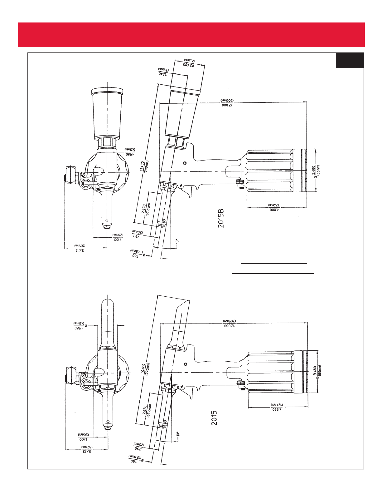
2015 Series Tooling Alcoa Fastening Systems
10
Good Service Practices
Service Kits, 2015KIT and 2015VKIT. include perishable
parts and should be on hand at all times. Other compo-
nents, as experience dictates, should also be kept for
replacements. ALWAYS REPLACE O-RINGS AND
BACK-UP RINGS WHEN TOOL IS DISASSEMBLED
FOR ANY REASON.
The efficiency and life of any tool depends upon proper
maintenance and good service practices. Tool should be
serviced by personnel who are thoroughly familiar with it
and how it operates.
A clean, well-lighted area should be available for servic-
ing the tool. Special care must be taken to prevent con-
tamination of pneumatic and hydraulic systems. Proper
hand tools and soft materials to protect tools must be
available, Use only standard hand tools, brass drift and
wood block. Vise with soft jaws should be available.
Unsuitable hand tools will cause installation tool damage.
All parts must be handled carefully and examined for
damage and/or wear. Components should be disassem-
bled and assembled in a straight line without bending,
cocking or undue force. Disassembly and assembly pro-
cedures outlined in this manual should be followed. If
Huck recommended procedures are not followed, the tool
may be damaged.
Rub SLIC-TITE TEFLON* thread compound, or equiva-
lent, on pipe plug threads and quic connect fitting.
CAUTION: Do not use TEFLON tape on pipe threads.
Pipe threads may cause tape to shred resulting in
tool malfunction. (SLIC-TITE is available in stick
form, as 503237, from Huck.)
Smear LUBRIPLATE 13OAA*, or equivalent lubricant, on
O-rings and mating surfaces to aid assembly and to pre-
vent damage to O-rings. (LUBRIPLATE 13OAA is avail-
able in a tube, as 502723, from Huck.)
Use VIBRA-TITE* or equivalent on Gland Housing Assy,
116134-1, threads. Torque to 75-80 ft. lbs.
Apply LOCKTITE* #271 Adhesive/sealant to Locknut,
505420. (LOCKTITE is available from Huck, in a tube, as
503657.) Torque to 25-30 ft. lbs.
* TEFLON is a trademark of E.l. DuPont de
Nemours & Co.
* LOCTITE is a trademark of Loctite Corp.
* TRUARC is a trademark of Waldes Kohinoor, Inc.
* VIBRA-TITE is a trademark of the Oakland
Corporation.
* LUBRIPLATE is a trademark of Fiske Brothers
Refining Co.
Standard Tools Available from Huck
1/8 hex key 502294 used on button head screw 504127.
5/32 hex key 502295 used on socket cap screw 123756.
(0400) TRUARC pliers 502866 used on (N5100-l00)
retaining ring.
MAINTENANCE
Tool Maintenance
The 2013 series require a minimum amount of mainte-
nance. Regular inspection and correction of minor prob-
lems will keep the tool operating efficiently and prevent
downtime.
Using filter-regulator-lubricator unit is highly recommend-
ed for safe and reliable tool operation. If a filter-regulator-
lubricator unit is not being used in the air supply: (1)
remove hose fitting from air inlet connector and drop in a
few drops of automatic transmission fluid or light oil (2)
blow out air line to remove dirt and water before connect-
ing air hose to tool. At regular intervals, depending upon
use, replace all seals in tool. Service Kits should be kept
on hand. (See SPARE PARTS AND SERVICE KITS.)
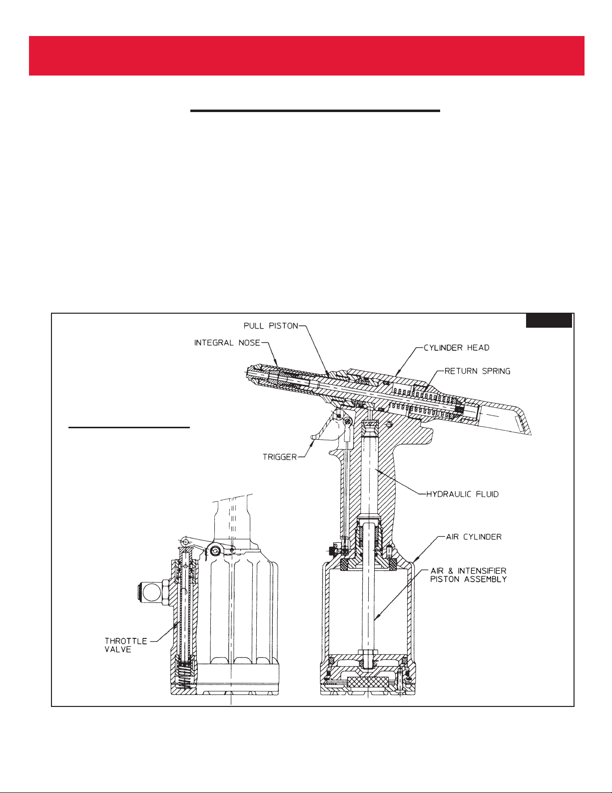
Inspect both hydraulic pistons, and their piston rods for
scored surfaces, excessive wear or damage, and replace
as necessary.
Always replace seals and back-up rings when tool is
disassembled for any reason to assure proper sealing
and tool function.
Nose Assembly Maintenance
CAUTION: Damaged jaw teeth, or debris packed
between teeth, will result in failure to install fastener
or improperly installed fastener.
Frequently cleaning the nose assembly is recommended.
Remove nose assembly from tool and disassemble. See
DISASSEMBLY Check components for any signs of dam-
age, e.g. cracks, scores and spring damage. Check grip-
per teeth for damage. Remove any debris packed
between teeth with a sharp pointed ‘pick’. Periodically dip
nose, while cycling tool, in mineral spirits, isopropyl alco-
hol or other suitable solvent, to clean jaws and wash
away metal chips and dirt.
PREVENTIVE MAINTENANCE