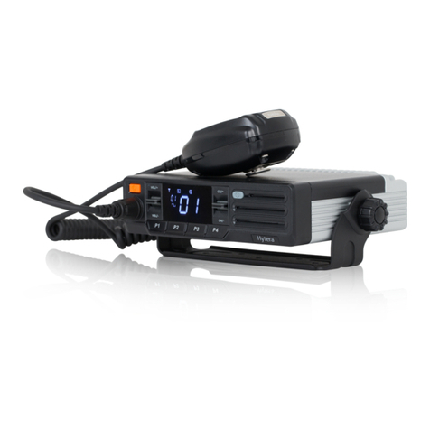
Hytera TM-610 User manual

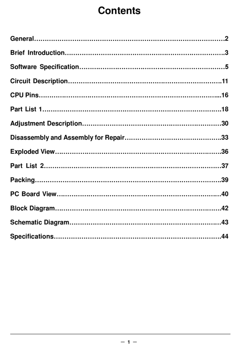
CONTENTS
Revision History……………………………………………………………………
General………………………………………………………………………………
Radio Overview…………………………………………………………….………
Software Specification…………………………………………………………
Circuit Description…………………………………..…………………………..
Semiconductor Data………………………………………………………….
Component Description…………………………..…………………………
TM-610 Parts List 1…………………………………………………….…………
V Tx-Rx Unit……………………………….…………………………………………….…………
U1 Tx-Rx Unit……..……………………………………………………….………………………
U1 VCO Unit…………….……………………………………………….…………………………
U2 Tx-Rx Unit………………..…………………………………………….………………………
U2 VCO Unit………….………………………………………………….…………………………
U&V Display Unit…………….…………………………………………….……………………
Tuning De scri pti on… ………… ………………… ………… ……….……
Troubleshooting Flow Chart………………………… ..………………
Disassembly and Reassembly for Repair…………………………………..
Exploded View……………………………………………………..……………
TM-610 Parts List 2…………………………………………………..………….
Packing………………………………………………...…………………………
Terminal Function…………………………………………… ……………
PC Board View………………………………………………………………………..
Schematic Diagram…………………………………………………………….
Block Diagram……………………………………………………………….…
Specifications……………………………………………….…………………

1
Revision History
Version Date Contents Revised
Parts No. 2006 October Initial release
General
Manual Scope
This manual is intended for use by experienced technicians familiar with similar types of
communication equipment. It contains all service information required for the equipment
and is current as of the publication date.
Precautions
Safety Standards
●DO NOT operate your radio when someone is either touching or standing within
2 or 3 feet of the antenna, to avoid the possibility of radio frequency burns or
related physical injury.
●DO NOT operate the radio near electrical blasting caps or in an explosive
atmosphere.
●Switch OFF the radio while refueling or parking at gas station.
●Turn off your radio in any place where posted notices instruct you to do so.
●DO NOT modify the radio for any reason.
●DO NOT expose the radio to direct sunlight over a long time, nor place it close to
heating source.
●DO NOT place the radio in excessively dusty, humid areas, nor on unstable
surfaces.
●Refer the service to qualified technicians only.
Operation Safety Guidelines
●For vehicles equipped with electronic anti-skid braking systems, electronic
ignition systems or electronic fuel injection systems, interferences may occur
during the radio transmission. If the foregoing electronic equipments are
installed on your vehicle, please contact your dealer for further assistance to
make sure that the radio transmission will not interfere with these equipments.
●For radio installation in vehicles fueled by LP gas with LP gas container within
interior of the vehicles, the following precautions are recommended for personal
safety.
(1) Any space containing radio equipment shall be isolated by a seal from the
space in which the LP gas container and its fittings are located.
2
(2) Remote (outside) fitting connections shall be used.
(3) Good ventilation is required for the container space.
Installation Safety Guidelines
●Do not mount the mobile radio overhead or on a sidewall unless you take special
precautions.
●If someone were to remove the radio and fail to replace it properly, road shock
could bump the radio loose, and the falling radio could, in some circumstances,
cause serious injury to the driver or a passenger. In a crash, even when properly
installed, the radio could break loose and become a dangerous projectile.

3
Radio Overview
Front Panel
①
Volume Control Knob
Turn the knob clockwise to adjust upwords and counter-clockwise downwards.
②
LCD Indicator
Please refer to “LCD Display” section.
③
Programmable Function Key
(
((
(
[▲] / [▼]
)
))
)
Your local dealer can programme these keys as shortcut to various auxiliary functions.
Please refer to “Programmable Function Key” section.
④
LED Indicator
⑤
Speaker
⑥
Power Switch
⑦
Programmable Function Key
(
((
(
[P1]/[P2]/[P3]/[P4]
)
))
)
Your local dealer can programme these keys as shortcut to various functions.
Please refer to “Programmable Function Key” section.
⑧
Mic Jack
Used for the plug of microphone.

4
Rear Panel Overview
①
15PIN (for external expansion)
②
External Speaker Jack
Used to connect external speaker and only available for the plug of 3.5 mm
③
Power Inlet
Adopt HYT-authorized DC power cable and 13.6 V DC power.
④
Antenna Pedestal
Used to connect external antenna.
Microphone

5
▇
LED Indicator
Indicator Description
Light red Transmitting
Light green Receiving
Flash orange Receiving encode squelch, selective call, 2-Tone call
▇
Programmable Function Keys
[P1]-[P4], [▲]/ [▼] can be programmed with the following auxiliary functions:
1. Off
2. Channel Up
3. Channel Down
4. Zone Up
5. Zone Down
6. Moni A
7. Moni B
8. Moni C
9. Moni D
10. Display Channel Frequency
11. Display Mode
12. User Selectable Signal
13. Sel 2-Tone
14. Sel 5-Tone
15. Scan
16. Add/Del
17. Reverse
18. Talkaround
19. SEL SQL
20. Home Channel
21. Public Adress
22. Scrambler
23. Compander
24. Emergency Call
▇
LCD Display
Figure 1 LCD Panel

6
Indicator Description
1. Display zone / channel number.
2. Display zone / channel label
3. Display DTMF digit
4. Display channel Frequency
5. Display menu, setting items, etc.
Lo
Display when the transmitting power is low.
Press Moni Key
1.
“ ”
appears when CTCSS/DCS
,
2-Tone encoder is
disabled.
2.
“ ”
appears when the loudspeaker is on.
Appears when busy channel (non-priority channel) is scanned.
Appears when call transmission is selected.
Icon C indicating that the selected channel is contained in the
scan list.
Icon Z indicating multi group scan.
Appears when scrambler function is enabled.
Appears when compander function is enabled.
Appears when the selected channel is busy.
Appears when the selected channel is programmed as priority
channel.
P• for priority channel 1, while P.for priority channel 2. P:for
priority channel 1 and 2.

7
Software Specification
1. Frame of Radio Modes
2. Keypad Entry for Mode Startup
Mode Display Operation Remarks
User Mode
-----------
--------
Power on the radio to enter User
Mode
Conventional
Mode
Tuning Mode
-----------
--------
Press and hold [P1] to turn the
radio on.
Model Set Mode
-----------
--------
Press and hold [P2] to turn the
radio on.
Clone Mode
-----------
----
Press and hold [P3] to turn the
radio on.
Firmware Version Display Mode
------- Press and hold [P4] to turn the
radio on.
Firmware Version Display Mode
Panel Tuning Mode
Conventional Mode
User Mode
Model Set Mode
Clone Mode
Wired Clone Mode
Wireless Clone Mode
PC Mode

8
PC Mode
-----------
---------
---------
Connect PC with mobile radio via
programming cable and send
commands via PC.
1. User Mode
Turn the power to enter this mode, common use mode.
2. Panel Tuning Mode
The operations of Tuning Mode are described as following:
1) Press [P1] to power on the radio. The radio enters Tuning Mode.
2) Use [Up]/[Down] to select setting items. Press [P4] to enter the sub-item of the
selected item.
3) Press [P4] to enter the sub-item. Press [Up]/[Down] to adjust the parameter. Press [P4]
again to save data and move to next item; or press [P1] to return to previous menu
without saving data.
Setting items and display(
***:1-256)
Setting item Main LCD
Wideband/
Narrowband
Frequency
Sub LCD Description
TX Power
TX HIGH High power
Wideband
Certer _C *** No signalling
Low _L *** No signalling
High _H *** No signalling
TX LOW Low frequency
Wideband
Center _C *** No signalling
Low _L *** No signalling
High _H *** No signalling
Max Deviation MAX.DEV
Wideband
Center _C *** No signalling
Low _L *** No signalling
High _H *** No signalling
Medium band Center M_C *** No signalling
Narrow band
Center N_C *** No signalling
Low N_L *** No signalling
High N_H *** No signalling
CDCSS Balance CDCSS.BAL
Wideband
Ceter _C *** 100Hz square wave
Low _L *** 100Hz square wave
High _H *** 100Hz square wave
Medium band Ceter M_C *** 100Hz square wave
Narrow band Ceter N_C *** 100Hz square wave

9
CTCSS Deviation
CTC.DEV_L
Wideband
Certer
_C ***
CTCSS 67.0Hz
Low
_L ***
CTCSS 67.0Hz
High
_H ***
CTCSS 67.0Hz
Medium Center
M_C ***
CTCSS 67.0Hz
Narrowband Center
N_C ***
CTCSS 67.0Hz
CTC.DEV_M
Wideband
Center
_C *** CTCSS
151.4
Hz
Low
_L *** CTCSS
151.4
Hz
High
_H *** CTCSS
151.4
Hz
Medium Center
M_C *** CTCSS
151.4
Hz
Narrowband Center
N_C *** CTCSS
151.4
Hz
CTC.DEV_H
Wideband
Center
_C *** CTCSS
254.1
Hz
Low
_L *** CTCSS
254.1
Hz
High
_H *** CTCSS
254.1
Hz
Medium Center
M_C *** CTCSS
254.1
Hz
Narrowband Center
N_C *** CTCSS
254.1
Hz
CDCSS
Deviation
CDCSS.DEV
Wideband
Center
_C *** CDCSS 023N
Low
_L *** CDCSS 023N
High
_H *** CDCSS 023N
Medium Center
M_C *** CDCSS 023N
Narrowband Center
N_C *** CDCSS 023N
DTMF Deviation
DTMF.DEV
Wideband
Center
_C *** DTMF 9
Low
_L *** DTMF 9
High
_H *** DTMF 9
Medium Center
M_C *** DTMF 9
Narrowband Center
N_C *** DTMF 9
MSK Deviation
MSK.DEV
Wideband
Center
_C *** 0XAAA…
Low
_L *** 0XAAA…
High
_H *** 0XAAA…
Medium Center
M_C *** 0XAAA…
Narrowband Center
N_C *** 0XAAA…
Single Tone
Deviation
TONE DEV
Wideband
Center
_C *** 1KHz
Low
_L *** 1KHz
High
_H *** 1KHz
Medium Center
M_C *** 1KHz
Narrowband Center
N_C *** 1KHz

10
Rx Sensitivity SENSITVITY
TY
- Low _L *** No signalling
,
SQL off
- Low-
medium
frequency _LC *** No signalling
,
SQL off
- Center _C *** No signalling
,
SQL off
- Medium-high
_HC *** No signalling
,
SQL off
High
_H ***
No signalling
,
SQL off
SQL Open
OPENSQL
9
SQL 9
Wideband
Center
_C ***
No signalling
Low
_L ***
No signalling
High
_H ***
No signalling
OPENSQL
3
SQL 9 Medium
Center
M_C ***
No signalling
SQL 9
Narrowband
Center
N_C ***
No signalling
Low
N_L ***
No signalling
High
N_H ***
No signalling
SQL 3
Wideband
Center
_C ***
No signalling
Low
_L ***
No signalling
High
_H ***
No signalling
SQL 3 Medium
Center
M_C ***
No signalling
SQL 3
Narrowband
Center
N_C ***
No signalling
Low
N_L ***
No signalling
High
N_H ***
No signalling
SQL Close
CLOS.SQL
9
SQL 9
Wideband
Center
_C ***
No signalling
Low
_L ***
No signalling
High
_H ***
No signalling
SQL 9 Medium
Center
M_C ***
No signalling
SQL 9
Narrowband
Center
N_C ***
No signalling
Low
N_L ***
No signalling
High
N_H ***
No signalling
CLOS.SQL
3
SQL 3
Wideband
Center
_C ***
No signalling
Low
_L ***
No signalling
High
_H ***
No signalling
High
_H ***
No signalling
SQL 3 Medium
Center
M_C ***
No signalling
SQL 3
Narrowband
Center
N_C ***
No signalling
Low
N_L ***
No signalling
High
N_H ***
No signalling
3. Model Set Mode
1) Press [P2] to turn the radio on. The radio enters Model Set Mode. “DESTINA.*”and
the selected model number are displayed on LCD.

11
2) Press [Up]/[Down] to choose model No. 0-5.
3) Press [P4] to confirm. LED glows orange with
“WAIT”
on LCD; then the radio
enters User Mode after reset.
Note: 1. Once [P4] key is pressed to set the new model, the previously stored channel
data (frequency, CTCSS/CDCSS, channel function settings) will be cleared, and part of
functions also changes. Therefore, do not make this operation unless it’s very necessary,
such as replacing the EEPROM, etc.
2. Initialization Data Table and frequency range (FL: lowest frequency- FH: highest
frequency -FC: center frequency) of different models are shown in the following table.
Model RX/TX 1 ( C ) 2 ( L ) 3 ( H ) 4 5 6 7 8
0 RX(MHz) 155.15 136.15 173.85 145.55 164.50 155.00 155.20 155.40
(
V
)
TX(MHz) 155.00 136.00 174.00 145.50 164.50 155.00 155.20 155.40
1 RX(MHz) 435.15 400.15 469.85 417.55 452.50 435.00 435.20 435.40
(
U1
)
TX(MHz) 435.00 400.00 470.00 417.50 452.50 435.00 435.20 435.40
2 RX(MHz) 475.15 450.15 499.85 462.55 487.50 475.00 475.20 475.40
(
U2
)
TX(MHz) 475.00 450.00 500.00 462.50 487.50 475.00 475.20 475.40
3 RX(MHz) 505.15 480.15 529.85 492.55 517.50 505.00 505.20 505.40
(
U3
)
TX(MHz) 505.00 480.00 530.00 492.50 517.50 505.00 505.20 505.40
4 RX(MHz) 375.15 350.15 399.85 362.55 387.50 375.00 375.20 375.40
(
U4
)
TX(MHz) 375.00 350.00 400.00 362.50 387.50 375.00 375.20 375.40
TM-610V:136-174;
TM-610U1:400-470;
TM-610U2:450-500;
TM-610U3:480-530;
TM-610U4:350-400;
CH 1 2 3 4 5 6 7 8
CTCSS
RX OFF OFF OFF OFF CTS67.0H
Z DI454 151.4 DI454
CDCSS
TX OFF OFF OFF OFF CTS67.0H
Z DI454 151.4 DI454
PWR TX H H H L L L L L
CH CH 1 CH 2 CH 3 CH 4 CH 5 CH 6 CH 7 CH 8
N
NAME
Wide Wide Wide N Wide Wide N

12
4. Clone Mode
Data can be transferred from radio to radio either by wired cloning or wireless cloning
■
Wired Clone Mode
1) Press and hold down [P3] to power on the source radio. The radio enters Clone
mode with “
CLONE
” displayed on numeric display. Or the radio enters User Mode when
Clone Mode is set OFF by your local dealer.
2) Press [P3] to toggle between Dealer Clone and Factory Clone Mode. “DEACLONE”
or “FACCLONE.” appears on the display when the corresponding mode is selected.
The display reverts to the original after 5 seconds. The Dealer Clone Mode does not
clone adjusted data, embedded information,etc. While Factory Clone Mode clones all
data. The default clone mode is Dealer Clone Mode.
3) Connect the source radio with wired clone cable and power it on.
4) Press [P4] to start cloning. The LED of source radio glows red and the data is
transferred from source radio to the target radio. When receiving data, the target
glows green with “PROGRAM” on LCD. When the cloning is completed, the source
radio displays “END”. The target radio automatically enters user mode after
receiving all data.
5) Press [P4] to return the source radio to clone mode. “CLONE” appears on LCD.
Repeat the above steps to continue wired clone.
■
Wireless Clone Mode
1
)
Press [P3] to power on the source radio. The radio enters Clone Mode with “CLONE”
displayed on the display. Or the radio enters User Mode when Clone Mode is set OFF
by your local dealer.
2
)
Press [P1] to enter Wireless Clone Mode and “WIRELESS” appears on LCD. Channel
frequency of wireless clone displays on LCD after two seconds (proceeding wireless
clone at this frequency). Press [P1] again to return to Clone Mode. Press [Down] to
switch to Wireless Clone channel.
3
)
Press [P3] to toggle between Dealer Clone and Factory Clone Mode in Clone Mode or
Wireless Clone Mode. “DEACLONE" and“FACCLONE”appears on the display when
the corresponding mode is selected. The display reverts to the original after 5 seconds.
The Dealer Clone Mode does not clone adjusted data, embedded information,etc.
While Factory Clone Mode clones all data. The default clone mode is Dealer Clone
Mode.
4
)
Repeat step 1-2 to operate the target radio, the frequency is set the same as that of
source radio. Place the target radio next to the source radio and Press [P4] on the
source radio to start cloning.
5) The LED of source radio glows red and the data is transferred from source radio to the
target radio. “ TX 00% ” appears on LCD. 00 bit on the left side of LCD indicates data
cloning rate and increases at a basic unit of one as data is continuously transferred.
The target radio glows orange when receiving data with “ RX 00% ” and “BUSY” icon

13
on LCD. 00 bit on the left side of LCD indicates data cloning rate and increases at a
basic unit of one as data is continuously received.
6) The source radio flashes orange with “END” on LCD after the data transmission. Clone
frequency appears when [P1] is pressed. Repeat the above steps to continue cloning.
While the target radio reverts to Users Mode after receiving all data.
Note: Clone Mode can be enabled/disabled by your local dealer. Cloning is accessible
only when Clone Mode is enabled.
5. Firmware Version Display Mode
Press [P4] to power on the mobile radio and Firmware Version Display Mode appears
on LCD. Release [P4] to enter User Mode automatically.
6. PC Mode
Connect the mobile radio with PC via programming cable. The data can be written
to the radio from PC, and then saved into the EEPROM. Data programming and radio
adjustment are accessible by programming software.
1) “PROGRAMM” appears on LCD after data is transferred to the mobile radio from
the computer. LED glows green when data is written to the radio and red when data is
read from the radio. Radio will restart automatically when programming is completed.
2) The following parameters can be set through the programming software.
●High TX Power
●Low TX Power
●Maximum Frequency Deviation
●CDCSS Balance
●CTCSS Deviation
●CDCSS Deviation
●DTMF Deviation
●MSK Deviation
●Single Tone Deviation
●Rx sensitivity
●Squelch Level 9
●Squelch Level 3

14
3
.
..
.
Key Assignment
Programmable functional keys [P1]-[P4] and [▲] / [▼].
Key Assignment
No. Key Settings Display Remarks
1 [P1] Off
P1 Off None
CH Up
P1 CH Up Channel up
CH Down
P1 CH Down Channle down
Zone up
P1 Zone Up
Zone up
Zone down
P1 Zone Down
Zone down
MONI A
P1 Moni A Icon
MONI A:
Monitor Unmute-Momentary
MONI B
P1 Moni B Icon
MONI B:
Monitor Unmute-Toggle
MONI C [Default]
P1 Moni C Icon
MONI C:
Carrier Squelch-Momentary
MONI D
P1 Moni D Icon
MONI D:
Carrier Squelch-Toggle
Display CH Freq.
P1 DFreq Display Frequency
Display Switch Mode
P1 DMode
Channel No./Alias, Zone
No./Alias, CH Freq.
User Selectable Tone
P1 User Tone
Signalling 01-
32 and Signalling
CTCSS/DCS

15
Sel 2-Tone
P1 Sel 2-Tone
Select 2-Tone encode
Tx Power
P1 TX Power Icon
Display at low Tx power
Scan [Default]
P1 Scan
Scan
Add/Delete
P1 Add/Del
Add/Delete
e scan channel in
non-scan mode
P1 Del
Temperarily Deletee nuis
ance
channnel
Reverse
P1 Reverse
Reverse frequency
Talk Around
P1 TA
Talk Around
SEL SQL
P1 SELSQL
Selecte SQL
Home CH
P3 Home CH
Home channel
Public Address
P1 PA
Public address
Scrambler
P1 Scramble Icon
Scrambler
Compander
P1 Compand Icon
Compander
Emergency call
P1 Emergency
Emergency call

16
2
[
P2
]
Off
P2 Off
None
CH Up
P2 CH Up
Channel up
CH Down
P2 CH Down
Channle down
Zone up
P2 Zone Up
Zone up
Zone down
P2 Zone Down
Zone down
MONI A
P2 MoniA Icon
MONI A:
MONI B
P2 MoniB Icon
Monitor Unmute-Momentary
MONI C [Default]
P2 MoniC Icon
MONI C:
Carrier Squelch-Momentary
MONI D
P2 MoniD Icon
MONI D:
Carrier Squelch-Toggle
Display CH Freq.
P2 DFreq
Display Frequency
Display Switch Mode
P2 DMode
Channel No./Alias, Zone
No./Alias, CH Freq.
User Selectable Tone
P2 User Tone
Signalling 01-32 and
Signalling
CTCSS/DCS

17
Sel 2-Tone
P2 Sel 2-Tone
Select 2-Tone encode
Tx Power
P2 TX Power Icon
Display at low TX power
Scan [Default]
P2 Scan
Scan
Add/Delete
P2 Add/Del
Add/Delete
e scan channel in
non-scan mode
P2 Del
Temperarily Delete
e nuisance
channnel
Reverse
P2 Reverse
Reverse frequency
Talk Around
P2 TA
Talk Around
SEL SQL
P2 SELSQL
Selecte SQL
Home CH
P2 Home CH
Home channel
Public Address
P2 PA
Public address
Scrambler
P2 Scramble Icon
Scrambler
Compander
P2 Compand Icon
Compander
Emergency call
P2 Emergency
Emergency call

18
3
[
P3
]
Off
P3 Off
None
CH Up
P3 CH Up
Channel up
CH Down
P3 CH Down
Channle down
Zone up
P3 Zone Up
Zone up
Zone down
P43 Zone Down
Zone down
MONI A
P3 MoniA Icon
MONI A:
MONI B
P 3MoniB Icon
Monitor Unmute-Momentary
MONI C [Default]
P3 MoniC Icon
MONI C:
Carrier Squelch-Momentary
MONI D
P3 MoniD Icon
MONI D:
Carrier Squelch-Toggle
Display CH Freq.
P3 DFreq
Display Frequency
Display Switch Mode
P3 DMode
Channel No./Alias, Zone
No./Alias, CH Freq.
User Selectable Tone
P3 User Tone
Signalling 01-32 and
Signalling
CTCSS/DCS

19
Sel 2-Tone
P3 Sel2-Tone
Select 2-Tone encode
Tx Power
P3 TXPower Icon
Display at low TX power
Scan [Default]
P3 Scan
Scan
Add/Delete
P3 Add/Del
Add/Deletee scan channel in
non-scan mode
P3 Del
Temperarily De
letee nuisance
channnel
Reverse
P3 Reverse
Reverse frequency
Talk Around
P3 TA
Talk Around
SEL SQL
P3 SELSQL
Selecte SQL
Home CH
P3 HomeCH
Home channel
Public Address
P3 PA
Public address
Scrambler
P3 Scramble Icon
Scrambler
Compander
P3 Compand Icon
Compander
Emergency call
P3 Emergency
Emergency call
Other manuals for TM-610
1
Table of contents
Other Hytera Radio manuals

Hytera
Hytera PD98X User manual

Hytera
Hytera PNC 550 User manual

Hytera
Hytera HP60X User manual

Hytera
Hytera PD66Xi Um Series User manual

Hytera
Hytera PDC760 User manual

Hytera
Hytera PNC380 User manual

Hytera
Hytera TM-600 VHF User manual

Hytera
Hytera PTC760 User manual

Hytera
Hytera MD78X User manual

Hytera
Hytera PDC760UXB2 User manual

Hytera
Hytera HM652 User manual

Hytera
Hytera TC-320 User manual

Hytera
Hytera MT680 User manual

Hytera
Hytera MD622i User manual

Hytera
Hytera MD780 User manual

Hytera
Hytera BP36X User manual

Hytera
Hytera PD486 User manual

Hytera
Hytera PDC760 User manual

Hytera
Hytera HP6 0X User manual

Hytera
Hytera Jupiter TETRA User manual