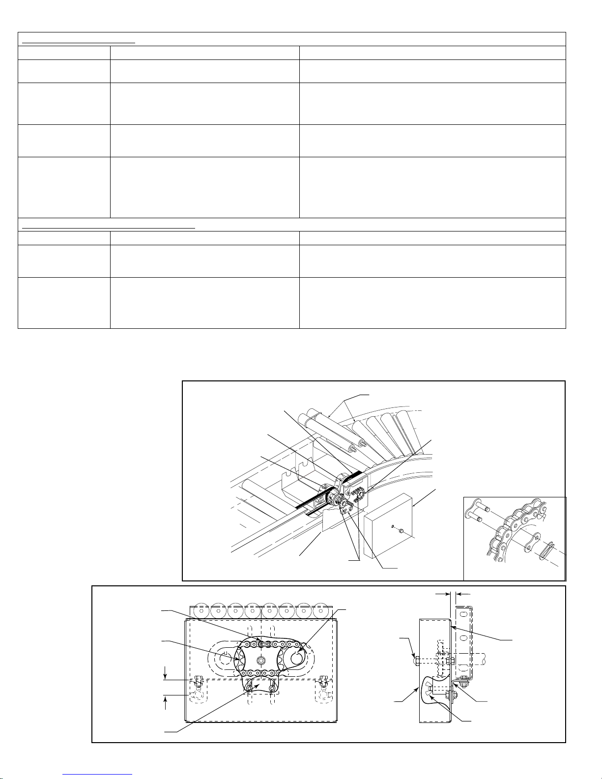
• Belt Alignment
190-LRC 90°
1. It is critical to align both idler sheaves with the drive sheaves so the belt
runs in the middle of the drive sheave to prevent belt wear.
2. Position a straight edge on the face of the drive sheave (on the bearing
side).
3. Move each idler sheave until the belt is parallel with the straight edge.
190-LRC 60°, 45°, and 30°
1. It is critical to align both idler sheaves with the drive sheaves so the belt
runs in the middle of the drive sheave to prevent belt wear.
2. Position a straight edge on the face of the drive sheave (on the channel
side).
3. Move each idler sheave until the belt is parallel with the straight edge.
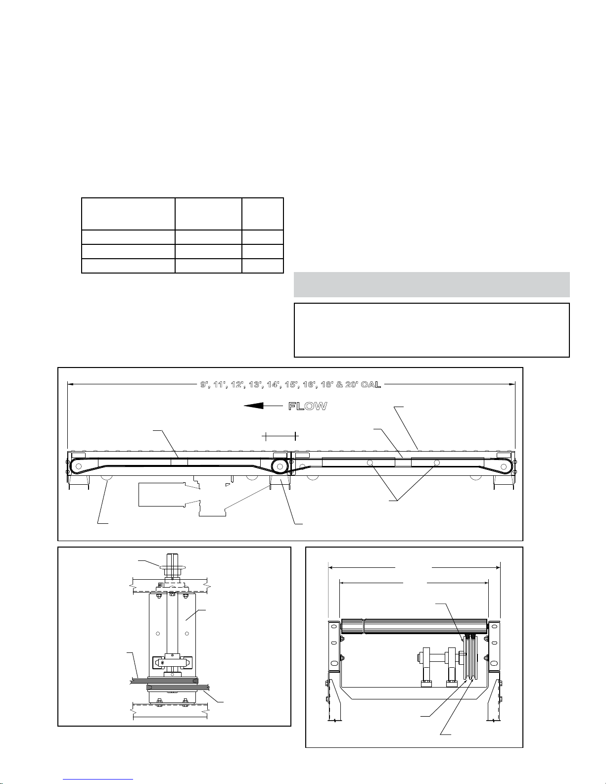
• Racked Sections
It is important that each bed section be checked for a “racked” or out-of-
square condition. If conveyor is not square, tracking problems will result.
Figure 6B indicates a racked section.
TO CORRECT AN OUT-OF-SQUARE SECTION
1. Locate points on corners of section and measure distance “A” & “B”. If the
dimensions are not equal, the section will need to be squared. (Figure 6C).
2. Use crossbracing supplied on underside of conveyor to square each
section. Adjust turnbuckle until Dimensions “A” & “B” are equal.
3. After all bed sections have been checked and corrected for “racked
condition”, tighten all butt couplings and pivot plate bolts.
4. Make final check to see that all conveyor sections are level across width
and length. If entire conveyor is level, supports can be lagged to floor.
• Electrical Equipment
CONTROLS
Electrical Code: All motor controls and wiring shall conform to the National
Electrical Code (Article 670 or other applicable articles) as published by
the National Fire Protection Association and as approved by the American
Standards Institute, Inc.
CONTROL STATIONS
A) Control stations should be so arranged and located that the operation of
the equipment is visible from them, and shall be clearly marked or labeled to
indicate the function controlled.
B) A conveyor which would cause injury when started shall not be started
until employees in the area are alerted by a signal or by a designated person
that the conveyor is about to start.
When a conveyor would cause injury when started and is automatically
controlled or must be controlled from a remote location, an audible device
shall be provided which can be clearly heard at all points along the conveyor
where personnel may be present. The warning device shall be actuated by
the controller device starting the conveyor and shall continue for a required
period of time before the conveyor starts. A flashing light or similar visual
warning may be used in conjunction with or in place of the audible device if
more effective in particular circumstances.
Where system function would be seriously hindered or adversely
affected by the required time delay or where the intent of the warning may
be misinterpreted (i.e., a work area with many different conveyors and allied
devices), clear, concise, and legible warning shall be provided. The warning
shall indicate that conveyors and allied equipment may be started at any time,
that danger exists, and that personnel must keep clear. The warnings shall be
provided along the conveyor at areas not guarded by position or location.
C) Remotely and automatically controlled conveyors, and conveyors where
operator stations are not manned or are beyond voice and visual contact from
drive areas, loading areas, transfer points, and other potentially hazardous
locations on the conveyor path not guarded by location, position, or guards,
shall be furnished with emergency stop buttons, pull cords, limit switches, or
similar emergency stop devices.
All such emergency stop devices shall be easily identifiable in the
immediate vicinity of such locations unless guarded by location, position, or
guards. Where the design, function, and operation of such conveyor clearly is
not hazardous to personnel, an emergency stop device is not required.
The emergency stop device shall act directly on the control of the
conveyor concerned and shall not depend on the stopping of any other
equipment. The emergency stop devices shall be installed so that they cannot
be overridden from other locations.
D) Inactive and unused actuators, controllers, and wiring should be removed
from control stations and panel boards, together with obsolete diagrams,
indicators, control labels, and other material which serve to confuse the
operator.
SAFETY DEVICES
A) All safety devices, including wiring of electrical safety devices, shall be
arranged to operate in a “Fail-Safe” manner, that is, if power failure or failure
of the device itself would occur, a hazardous condition must not result.
B) Emergency Stops and Restarts. Conveyor controls shall be so arranged
that, in case of emergency stop, manual reset or start at the location where
the emergency stop was initiated, shall be required of the conveyor(s) and
associated equipment to resume operation.
C) Before restarting a conveyor which has been stopped because of an
emergency, an inspection of the conveyor shall be made and the cause of
the stoppage determined. The starting device shall be locked out before
any attempt is made to remove the cause of stoppage, unless operation is
necessary to determine the cause or to safely remove the stoppage.
Refer to ANSI Z244.1-1982, American National Standard for Personnel
Protection – Lockout/Tagout of Energy Sources – Minimum Safety
Requirements and OSHA Standard Number 29 CFR 1910.147 “The Control
of Hazardous Energy (Lockout/Tagout).”
WARNING! Electrical controls shall be installed and wired by a qualified
electrician. Wiring information for the motor and controls are furnished by
the equipment manufacturer.
1. IT IS CRITICAL TO ALIGN BOTH IDLER SHEAVES WITH THE DRIVE
SHEAVES SO THE BELT RUNS IN THE MIDDLE OF THE DRIVE SHEAVE
TO PREVENT BELT WEAR.
2. POSITION A STRAIGHT EDGE ON THE FACE OF THE DRIVE SHEAVE
(ON THE CHANNEL SIDE).
3. MOVE EACH IDLER SHEAVE UNTIL THE BELT IS PARALLEL WITH THE
STRAIGHT EDGE.
NOTES FOR 60, 45 AND 30 DEGREE:
STRAIGHT EDGE
(BORDE RECTO)
IDLER
SHEAVE
(POLEA TENSORA)
DRIVE
SHEAVE
(POLEA
MOTRIZ)
NOTES FOR 90 DEGREE:
1. IT IS CRITICAL TO ALIGN BOTH IDLER SHEAVES WITH THE DRIVE
SHEAVES SO THE BELT RUNS IN THE MIDDLE OF THE DRIVE SHEAVE
TO PREVENT BELT WEAR.
2. POSITION A STRAIGHT EDGE ON THE FACE OF THE DRIVE SHEAVE
(ON THE BEARING SIDE).
3. MOVE EACH IDLER SHEAVE UNTIL THE BELT IS PARALLEL WITH THE
STRAIGHT EDGE.
DRIVE SHEAVE
(POLEA MOTRIZ)
IDLER
SHEAVE
(POLEA TENSORA)
STRAIGHT EDGE
(BORDE RECTO)
FIGURE 6A
1. IT IS CRITICAL TO ALIGN BOTH IDLER SHEAVES WITH THE DRIVE
SHEAVES SO THE BELT RUNS IN THE MIDDLE OF THE DRIVE SHEAVE
TO PREVENT BELT WEAR.
2. POSITION A STRAIGHT EDGE ON THE FACE OF THE DRIVE SHEAVE
(ON THE CHANNEL SIDE).
3. MOVE EACH IDLER SHEAVE UNTIL THE BELT IS PARALLEL WITH THE
STRAIGHT EDGE.
NOTES FOR 60, 45 AND 30 DEGREE:
STRAIGHT EDGE
(BORDE RECTO)
IDLER
SHEAVE
(POLEA TENSORA)
DRIVE
SHEAVE
(POLEA
MOTRIZ)
NOTES FOR 90 DEGREE:
1. IT IS CRITICAL TO ALIGN BOTH IDLER SHEAVES WITH THE DRIVE
SHEAVES SO THE BELT RUNS IN THE MIDDLE OF THE DRIVE SHEAVE
TO PREVENT BELT WEAR.
2. POSITION A STRAIGHT EDGE ON THE FACE OF THE DRIVE SHEAVE
(ON THE BEARING SIDE).
3. MOVE EACH IDLER SHEAVE UNTIL THE BELT IS PARALLEL WITH THE
STRAIGHT EDGE.
DRIVE SHEAVE
(POLEA MOTRIZ)
IDLER
SHEAVE
(POLEA TENSORA)
STRAIGHT EDGE
(BORDE RECTO)
6