HYTROL ProSort 100 Elite User manual

Installation
and
Maintenance
Manual
with Safety Information
and Parts List
RECOMMENDED SPARE PARTS HIGHLIGHTED IN GRAY
Manual
de Instalación
y
Mantenimiento
con Información sobre Seguridad
y Lista de Refacciones
LAS REFACCIONES RECOMENDADAS SE RESALTAN EN GRIS
IMPORTANT!
DO NOT DESTROY
¡IMPORTANTE!
NO DESTRUIR
PRESS OPTIMIZED FOR THE ENVIRONMENT
(IMPRESIÓN OPTIMIZADA PARA PROTEGER EL MEDIO AMBIENTE)
HYTROL | Jonesboro, Arkansas
© COPYRIGHT PENDING–HYTROL CONVEYOR CO., INC.
May 2017
(Supersedes August 2000)
Bulletin #695
Model ProSort 100 Elite

TABLE OF CONTENTS
INTRODUCTION
Receiving and Uncrating ........................2
How to Order Replacement Parts .................2
SAFETY INFORMATION .............................3
INSTALLATION
Location .....................................4
Conveyor Set-Up ..............................4
Electrical Equipment............................5
OPERATION
Conveyor Start-Up .............................5
MAINTENANCE
Lubrication ...................................6
Oiler Brush Adjustment..........................6
Controlling the ProSort......................6, 7, 8
Pneumatic Divert Switch Checklist.................8
Electric Divert Switch Checklist ...................8
Carrying Chain Installation.......................9
Install Guard Rails at Divert Locations..............9
Locating the Spurs .............................9
Pneumatic Divert Switch Removal Procedure .......10
Electric Divert Switch Removal Procedure..........10
Electric Switch Homing Procedure................10
Trouble Shooting .............................11
Maintenance Checklist .................Back Cover
REPLACEMENT PARTS
Lost Pin Prox Assembly
Parts Drawing & List...........................11
Pneumatic Divert Switch Assembly
Parts Drawing & List...........................12
Electric Divert Switch Assembly
Parts Drawing & List...........................13
Safety Switch Assembly
Parts Drawing & List...........................13
ProSort 131 Parts Drawings
Catenary Divert, Return Divert, & Drive Section .....14
Intermediate Divert & Tail Section ................15
Induction Unit . . . . . . . . . . . . . . . . . . . . . . . . . . . . . . . .16
Intermediate Section Assembly ..................17
30° Divert Section.............................17
ProSort 131 Parts List ......................18, 19
ProSort 121 Parts Drawings
Catenary Divert, Return Divert, & Drive Section .....20
Intermediate Divert & Tail Section ................21
Induction Unit . . . . . . . . . . . . . . . . . . . . . . . . . . . . . . . .22
Intermediate Section Assembly ..................23
22° Divert Section.............................23
ProSort 121 Parts List ......................24, 25
ProSort 132 Parts Drawings
Catenary Divert & Drive Section .................26
Dual Divert & Divert Return .....................27
Dual Divert Return Switch & Tail .................28
Induction Unit . . . . . . . . . . . . . . . . . . . . . . . . . . . . . . . .29
ProSort 132 Parts List ......................30, 31
ProSort 122 Parts Drawings
Catenary Divert & Drive Section .................32
Dual Divert & Divert Return .....................33
Dual Divert Return Switch & Tail .................34
Induction Unit . . . . . . . . . . . . . . . . . . . . . . . . . . . . . . . .35
ProSort 122 Parts List ......................36, 37
Spanish Version ......................38
INTRODUCTION
This manual provides guidelines and procedures for installing,
operating, and maintaining your conveyor. A complete parts list
is provided with recommended spare parts highlighted in gray.
Important safety information is also provided throughout the manual.
For safety to personnel and for proper operation of your conveyor, it
is recommended that you read and follow the instructions provided
in this manual.
• Receiving and Uncrating
1. Check the number of items received against the bill of lading.
2. Examine condition of equipment to determine if any damage
occurred during shipment.
3. Move all crates to area of installation.
4. Remove crating and check for optional equipment that may be
fastened to the conveyor. Make sure these parts (or any foreign
pieces) are removed.
• How to Order Replacement Parts
Includedinthismanualarepartsdrawingswithcomplete replacement
parts lists. Minor fasteners, such as nuts and bolts, are not included.
When ordering replacement parts:
1. Contact Dealer from whom conveyor was purchased or nearest
HYTROL Integration Partner.
2. Give Conveyor Model Number and Serial Number or HYTROL
Factory Order Number.
3. Give Part Number and complete description from Parts List.
4. If you are in a breakdown situation, tell us.
HYTROL Serial Number
(Located near Drive on Powered Models).
NOTE: If damage has occurred or freight is missing,
Contact your Hytrol Integration Partner.
Hytrol Conveyor
Company, Inc.
JONESBORO, ARKANSAS
SERIAL # 123456
YEAR
QR
CODE
2

SAFETY INFORMATION
• Installation
GUARDS AND GUARDING
Interfacing of Equipment. When two or more pieces of equipment
are interfaced, special attention shall be given to the interfaced area
to insure the presence of adequate guarding and safety devices.
Guarding Exceptions. Whenever conditions prevail that would
require guarding under these standards, but such guarding would
render the conveyor unusable, prominent warning means shall be
provided in the area or on the equipment in lieu of guarding.
Guarded by Location or Position. Where necessary for the
protection of employees from hazards, all exposed moving machinery
parts that present a hazard to employees at their work station shall
be mechanically or electrically guarded, or guarded by location or
position.
• Remoteness from frequent presence of public or employed
personnel shall constitute guarding by location.
• When a conveyor passes over a walkway, roadway, or work
station, it is considered guarded solely by location or position
if all moving parts are at least 8 ft. (2.44 m) above the oor or
walking surface or are otherwise located so that the employee
cannot inadvertently come in contact with hazardous moving
parts.
• Although overhead conveyors may be guarded by location, spill
guards, pan guards, or equivalent shall be provided if the product
may fall off the conveyor for any reason and if personnel would
be endangered.
HEADROOM
• When conveyors are installed above exit passageways, aisles,
or corridors, there shall be provided a minimum clearance of 6
ft. 8 in. (2.032 m) measured vertically from the oor or walking
surface to the lowest part of the conveyor or guards.
• Where system function will be impaired by providing the
minimum clearance of 6 ft. 8 in. (2.032 m) through an emergency
clearance, alternate passageways shall be provided.
• It is permissible to allow passage under conveyors with less
than 6 ft. 8 in. (2.032 m) clearance from the oor for other than
emergency exits if a suitable warning indicates low headroom.
• Operation
A) Only trained employees shall be permitted to operate conveyors.
Training shall include instruction in operation under normal conditions
and emergency situations.
B) Where employee safety is dependent upon stopping and/or
starting devices, they shall be kept free of obstructions to permit
ready access.
C) The area around loading and unloading points shall be kept clear
of obstructions which could endanger personnel.
D) No person shall ride the load-carrying element of a conveyor
under any circumstances unless that person is specically authorized
by the owner or employer to do so. Under those circumstances, such
employee shall only ride a conveyor which incorporates within its
supporting structure platforms or control stations specically designed
for carrying personnel. Under no circumstances shall any person ride
on any element of a vertical conveyor.
E) Personnel working on or near a conveyor shall be instructed as to
the location and operation of pertinent stopping devices.
F) A conveyor shall be used to transport only material it is capable
of handling safely.
G) Under no circumstances shall the safety characteristics of the
conveyor be altered if such alterations would endanger personnel.
H) Routine inspections and preventive and corrective maintenance
programs shall be conducted to insure that all safety features and
devices are retained and function properly.
I) Personnelshouldbealertedtothepotentialhazardofentanglement
in conveyors caused by items such as long hair, loose clothing, and
jewelry.
J) Conveyors shall not be maintained or serviced while in operation
unless proper maintenance or service requires the conveyor to be in
motion. In this case, personnel shall be made aware of the hazards
and how the task may be safely accomplished.
K) Owners of conveyor should insure proper safety labels are afxed
to the conveyor warning of particular hazards involved in operation of
their conveyors.
• Maintenance
• All maintenance, including lubrication and adjustments, shall be
performed only by qualied and trained personnel.
• It is important that a maintenance program be established to
insurethatallconveyorcomponentsaremaintainedina condition
which does not constitute a hazard to personnel.
• When a conveyor is stopped for maintenance purposes, starting
devices or powered accessories shall be locked or tagged out
in accordance with a formalized procedure designed to protect
all persons or groups involved with the conveyor against an
unexpected start.
• Replace all safety devices and guards before starting equipment
for normal operation.
• Whenever practical, DO NOT lubricate conveyors while they are
in motion. Only trained personnel who are aware of the hazard of
the conveyor in motion shall be allowed to lubricate.
Safety Guards
Maintain all guards and safety devices IN POSITION and IN SAFE
REPAIR.
Safety Labels
In an effort to reduce the possibility of injury to personnel working
around HYTROL conveying equipment, safety labels are placed at
various points on the equipment to alert them of potential hazards.
Please check equipment and note all safety labels. Make certain
your personnel are alerted to and obey these warnings. See Safety
Manual for examples of warning labels.
CAUTION! Because of the many moving parts on the conveyor, all
personnel in the area of the conveyor need to be warned that the conveyor
is about to be started.
REMEMBER Do not remove, reuse or modify material handling equipment
for any purpose other than it’s original intended use.
3

INSTALLATION
• Location
1. Determine direction of product flow.
Figure 4A indicates the flow as related
to the drive.
2. Refer to “Match-Mark” numbers on
ends of conveyor sections. (Figure 4A).
Position them in this sequence near
area of installation.
• Conveyor Set-Up
1. Mark a chalk line on floor to locate
center of the conveyor.
2. Attach supports and vibration pads to
all conveyor sections shown in Figures
4A and 4B. Adjust elevation to required
height. Hand tighten bolts only at this
time.
3. During installation, check to make
sure each bed section is square.
Measure the diagonals from corner to
corner of the frame. If they are not equal
the frame must be squared. Attach a
come-along or some other suitable pulling device across longest corners and pull until the section is
square.
4. Place the infeed (tail) section in position.
5. Install remaining sections, placing end without support on extended pivot plate of previous section
(Figure 4A).
6. Fasten sections together with splice plates and pivot plates. (Figure 4B).
7. Check to see that conveyor is level across the width and length of unit. Adjust supports as necessary.
8. After all sections have been squared and levelled, tighten all splice channels and support mounting
bolts and lag support to the floor.
9. Check alignment of wearstrip at all section joints. Sand wearstrip as necessary to provide a smooth
wear surface (Figure 4C).
10. Starting on the infeed end, fasten bearing profile to wearstrip guide using rubber mallet to force the
profile edge under the wearstrip (Figure 4C & 4F). Glue infeed end of profile to the support angle with
loctite # 401 or 454 adhesive.
11. Run 1/2” main air line the full length of the sorter, either on the outside attaching it to the bottom of
conveyor channel with cable ties, or through the bed spacer holes where rubber grommets are provided
on the inside of the channel. (Figure 4A). Connect 3/8”air lines at divert switches as shown in Figures
4D & 4E.
12. Connect main air line to the Filter/Regulator, (Figure 5A) Set regulator to working pressure of 60 P.S.I.
Install low pressure switch, at farthest point from regulator (Figure 4E).
13. Install electrical controls and wire motor. Verify correct motor rotation at this time. See Page 5 & 6 for
electrical control information.
14. Check each divert switch to see that it is operating properly. This must be done before carrying chains
are installed. See instructions on Page 8 & 9.
15. Check proximity switch clearance at each internal safety switch (Figure 5C). Adjust if necessary.
16. Install carrying chains per instructions on Page 8 & 9.
17. Install chain oiler at infeed and connect to oil lines as shown in Figure 5B. Refer to the Lubrication
section, page 6, for type of oil required. After mounting, the oiler will need to be adjusted for proper oiling
of mounting chains. Adjustment may be made using a combination of solenoid activation time and flow
adjustment screws. (A good rule of thumb for solenoid adjustment is to turn the oiler on for one complete
chain revolution for every 40 hours of sorter operation.) Typically, the chain on the divert side will need
slightly more oil; the flow adjustment screws can be altered to achieve volume. CAUTION: Do not allow
oil to drip on floor.
18. Locate spurs per instructions on Page 9.
FIGURE 4B
FLOW
MATCH MARK NUMBERS
(ETIQUETAS DE SCUENCIADE ARMADO)
KNEEBRACE
(SOPORTE ANGULAR)
INTERMEDIATE SUPPORT
(SOPORTE INTERMEDIOS)
DRIVE SUPPORT
(SOPORTE MOTRIZ)
DRIVE
(MOTOR)
CATENARY DIVERT
(DESVIACION CATENARIA)
RETURN DIVERT
(DESVIACION DE RETORNO)
INTERMEDIATE DIVERT
(DESVIACION INTERMEDIA)
TAIL
(RETORNO)
INFEED BELT DRIVE
(BANDA ALIMENTADORA
MOTRIZ)
INFEED INDUCTION BELT
(BANDA ALIMENTADORA DE INDUCCION)
5D
5A
4D
5B
4C 4E 4B 5C
FO:
MARK:
TOOL BOX
QR
CODE
H
Y
T
R
O
L
C
O
D
E
MODEL
A
FO:
MARK:
TOOL BOX
QR
CODE
H
Y
T
R
O
L
C
O
D
E
MODEL
A
(FLUJO)
FIGURE 4A
1/2" TEE
(TE DE 1/2")
MAIN AIR
(LINEA PRINCIPAL
DE AIRE)
3/8" TO 1/4" REDUCER
(REDUCTOR DE 3/8"A 1/4")
LINE TO VALVE
(LINEA A LA VALVULA)
1/2" TO 3/8" REDUCER
(REDUCTOR DE 1/2"A 3/8")
PRESSURE SWITCH
PRE SET AT 48 PSI
(INTERRUPTOR DE
PRESION AJUSTADO
A 48 PSI)
FIGURE 4E
3/8" LINE
(LINEA DE 3/8")
1/2" to 3/8" REDUCER
(REDUCTOR DE 1/2" A 3/8")
1/2" TEE
(TE DE 1/2")
1/2" MAIN LINE
(LINEA PRINCIPAL DE 1/2")
3/8" FEMALE TO 3/8" MALE
QUICK CONNECT FITTING
PLUG INTO VALVE
(HEMBRA DE 3/8" A MACHO DE 3/8"
DE RAPIDA CONEXION A VALVULA)
INTERMEDIATE
SWITCHES
(INTERRUPTORES
INTERMEDIOS)
FIGURE 4D
CHAIN COVER UHMW WEARSTRIP
CHAIN GUIDES
OVERLAP JOINT
BEARING PROFILE
BEARING PROFILE
UHMW
WEARSTRIP
CHAIN GUIDES OVERLAP
JOINT
SECTION JOINT
(SECCION DE UNION)
(TIRA DE DESGASTE
UHMW)
(JUNTA DE RECUBRIMIENTO
DE GUÍAS DE CADENA)
(PERFIL DEL
COJINETE)
(PERFIL DEL
COJINETE)
(CUBIERTA DE
CADENA ) (TIRA DE DESGASTE
UHMW)
(JUNTA DE RECUBRIMIENTO
DE GUÍAS DE CADENA)
FIGURE 4C
SIDE CHANNEL
(CANAL LATERAL)
VIBRATION PAD
(PROTECTORES
DE VIBRACION)
SPLICE
(EMPALME)
SIDE CHANNEL
(CANAL LATERAL)
PIVOT PLATE
(PLACA PIVOTE)
BED SPACER
(ESPACIADOR
DE CAMA)
BED SPACER
(ESPACIADOR DE CAMA)
FIGURE 4B
FORCE BEARING
PROFILE UNDER
WEARSTRIP
BEARING PROFILE
CHAIN GUIDE WEARSTRIP
CHAIN COVER
CHAIN GUIDE
MOUNTING ANGLE
(CUBIERTA DE
CADENA)
(SECCION DE UNION) (PERFIL DEL COJINETE)
(TIRA DE DESGASTE DE
GUÍA DE CADENA)
(FUERCE EL PERFIL DEL
COJINETE DEBAJO DE
LA TIRA DE DESGASTE)
FIGURE 4F
4

• Electrical Equipment
CONTROLS
Electrical Code: All motor controls and wiring shall conform to the National Electrical Code (Article 670
or other applicable articles) as published by the National Fire Protection Association and as approved
by the American National Standards Institute.
CONTROL STATIONS
A) Control stations should be so arranged and located that the operation of the equipment is visible
from them, and shall be clearly marked or labeled to indicate the function controlled.
B) Aconveyor which would cause injury when started shall not be started until employees in the area
are alerted by a signal or by a designated person that the conveyor is about to start.
When a conveyor would cause injury when started and is automatically controlled or must be
controlled from a remote location, an audible device shall be provided which can be clearly heard at all
points along the conveyor where personnel may be present. The warning device shall be actuated by
the controller device starting the conveyor and shall continue for a required period of time before the
conveyor starts. A flashing light or similar visual warning may be used in conjunction with or in place
of the audible device if more effective in particular circumstances.
Where system function would be seriously hindered or adversely affected by the required time
delay or where the intent of the warning may be misinterpreted (i.e., a work area with many different
conveyors and allied devices), clear, concise, and legible warning shall be provided. The warning shall
indicate that conveyors and allied equipment may be started at any time, that danger exists, and that
personnel must keep clear. The warnings shall be provided along the conveyor at areas not guarded
by position or location.
C) Remotely and automatically controlled conveyors, and conveyors where operator stations are
not manned or are beyond voice and visual contact from drive areas, loading areas, transfer points,
and other potentially hazardous locations on the conveyor path not guarded by location, position,
or guards, shall be furnished with emergency stop buttons, pull cords, limit switches, or similar
emergency stop devices.
All such emergency stop devices shall be easily identifiable in the immediate vicinity of such
locations unless guarded by location, position, or guards. Where the design, function, and operation
of such conveyor clearly is not hazardous to personnel, an emergency stop device is not required.
The emergency stop device shall act directly on the control of the conveyor concerned and shall
not depend on the stopping of any other equipment. The emergency stop devices shall be installed so
that they cannot be overridden from other locations.
D) Inactive and unused actuators, controllers, and wiring should be removed from
control stations and panel boards, together with obsolete diagrams, indicators, control
labels, and other material which serve to confuse the operator.
SAFETY DEVICES
A) All safety devices, including wiring of electrical safety devices, shall be arranged
to operate in a “Fail-Safe” manner, that is, if power failure or failure of the device itself
would occur, a hazardous condition must not result.
B) Emergency Stops and Restarts. Conveyor controls shall be so arranged that, in
case of emergency stop, manual reset or start at the location where the emergency
stop was initiated, shall be required of the conveyor(s) and associated equipment to
resume operation.
C) Before restarting a conveyor which has been stopped because of an emergency,
an inspection of the conveyor shall be made and the cause of the stoppage
determined. The starting device shall be locked out before any attempt is made to
remove the cause of stoppage, unless operation is necessary to determine the cause
or to safely remove the stoppage.
Refer to ANSI Z244.1, American National Standard for Personnel Protection –
Lockout/Tagout of Energy Sources – Minimum Safety Requirements and OSHA
Standard Number 29 CFR 1910.147 “The Control of Hazardous Energy (Lockout/
Tagout).”
OPERATION
• Conveyor Start-Up
Before conveyor is turned on, check for foreign objects that may have been left inside
conveyor during installation. These objects could cause serious damage during start-
up.
After conveyor has been turned on and is operating, check all moving parts to make
sure they are working freely.
WARNING! Electrical controls shall be installed and wired by a qualied electrician. Wiring information
for the motor and controls are furnished by the equipment manufacturer.
AIR SUPPLY TO
AIR VALVES
(SUMINISTRO DE
AIRE A LAS
VALVULAS)
1/2" UNION TEE
(UNION TE DE 1/2")
BOWL GUARD
(TAZON PROTECTOR)
FILTER/REGULATOR
(REGULADOR/FILTRO)
GAUGE
(MEDIDOR)
MAIN AIR
SUPPLY
LINE
(SUMINISTRO
PRINCIPAL
DE AIRE)
MOUNTING BRACKET
(FASTEN TO
CONVEYOR CHANNEL)
(PLACA DE MONTAJE
[SUJETAR AL CANAL
DEL TRANSPORTADOR])
LOCK-OUT VALVE
(VÁLVULA DE BLOQUEO)
FIGURE 5A
OIL CUP
(RECIPIENTE
DE ACEITE)
ADJUSTMENT SCREWS
(TORNILLOS DE AJUSTE)
OIL LINES TO BRUSHES
(LINEAS DE ACEITE
PARA LAS BROCHAS)
FIGURE 5B
SWITCH SENSOR
(INTERRUPTOR
DEL SENSOR)
PROXIMITY SWTICH
(INTERRUPTOR DEL
PROXIMIDAD)
1/8"-3/16" FROM PROX
FACE TO METAL PLA
TE
(1/8" - 3/16" DESDE LA
SUPERFICIE DE
PROXIMIDAD HASTA
LA PLACA METÁLICA)
L
TRANSITION ASSEMBLY
DETAIL
(DETALLE DE CONJUNTO
DE TRANSICIÓN)
FIGURE 5D
FIGURE 5C
CAUTION! Because of the many moving parts on the conveyor, all personnel in the area
of the conveyor need to be warned that the conveyor is about to be started.
5

MAINTENANCE
• Lubrication
BEARINGS
A) NO GREASE FITTING - Prelubricated - No lubrication required.
B) WITH GREASE FITTING - Relubricate approximately every 10 to 12 weeks with
lithium base grease suitable for ball bearing service.
RECOMMENDED CHAIN LUBRICANT
A good grade of clean non-detergent petroleum or synthetic oil is recommended.
See chart for proper viscosity.
REDUCERS
See recommendations by manufacturer.
OILER BRUSH ADJUSTMENT
It is very important that the oiler brush comes in contact with the chain for proper
lubrication and increased chain life. This can be done by using the adjusting nuts
and support brackets.
• Controlling the ProSort
Agood software package is essential for the proper operation of the ProSort sorter.
With proper controls, the sorter will provide accurate, efficient, reliable sorting for
many years. Inadequate controls, however, may result in poor sorter performance
and other mechanical failures of the sorter itself, including “crashes”. Hytrol
recommends using the Hytrol ProLogix software package.
Every sortation system is different, which means that the controls for the system
are custom and unique to that system. These custom controls are provided either
by Hytrol, the Hytrol Integration Partner or a third party.
Hytrol has built into the sorter some of the controls necessary to operate the divert
switches, eliminating the need to control this function externally. Other electrical
control components are provided with the sorter to allow the external controls to
monitor critical items and to provide an interface between the electrical controls
and the mechanical sorter. Still other control components must be provided by the
supplier of the custom controls package to insure proper sorter operation.
This section of the manual includes the following information for the custom
controls provider:
1.Adescription of the divert switch control components supplied, their function, and
how to interface with them.
2. A description of the other control components provided with the sorter and their
intended function.
3. A description of control components that are not included with the sorter that
must be provided by the controls supplier.
4. Some control do’s and dont’s to assist in the design and installation of the
controls package.
Please read this section thoroughly and share this information with the controls
provider.
DIVERT SWITCH CONTROL
Proper control of the divert switch is critical to the safe and reliable operation of
the sorter. Failure to properly control the divert switch is one of the most common
causes of switch damage and can cause “crashes.”
The divert switch functions similar to a switch on a train track to cause the divert
shoes to travel either in a straight-through, “non-divert” track or diagonally across
the sorter along a “divert track” to push product off of the sorter. When the switch is
in the “home” position, the divert shoes travel through the switch along the straight-
through track. When the switch is in the “divert” position, the shoes are caused to
move along the divert track.
The transition of the switch between the “home” and “divert” positions must be
accurately timed to prevent sorter crashes. Just as a train track switch cannot
be safely operated while a train is passing through the switch, the divert switch
cannot be safely operated while a divert shoe is passing through the switch. If the
movement of the switch mechanism is not timed to occur only when no shoe is
present in the switch, the guide pin of the shoe may collide with the point of the
divert block, resulting in damage to the switch and potentially costly downtime.
The ProSort has two control components at each divert switch that work together
to accurately time the divert switch movement or operation, eliminating the need
for the controls provider to do so. These components are the smart prox and the
high-speed solenoid air valve.
SMART PROX
The “smart prox” is a special inductive proximity sensor developed exclusively for
Hytrol that has the “intelligence” needed to control the switch timing built-in. The
prox plugs to the y-cable. See Figure 6A.
Brown—+24VDC power input to the prox.
Blue—Ground (-) lead for the prox.
Gray—Divert enable input lead for the prox. When a 24VDC (high) signal is given
to this lead by the system controls, the prox waits for the next time it detects a
divert shoe, at which time it provides a 24VDC output through the y-cable to the
high speed solenoid air valve. The solenoid air valve then causes the switch to
move to “divert” position. All shoes traveling through the switch will then follow the
divert track as long as the enable signal is active (held high). When the divert signal
is removed (taken low) the prox waits for the next time it detects a divert shoe, at
which time it will turn off the output to the solenoid air valve.The switch then returns
to the “home” position, and subsequent shoes will follow the “non-divert” track. The
enable signal to this lead is the only signal that the system controls must
provide to control divert switching.
Y Cable
The y-cable is used to connect the smart prox, solenoid air valve and the system
controls. The male micro cord set from the smart prox connects to the terminal
#1 of the y-cable. The pico pigtail, of the y-cable, connects to the male plug on
the solenoid air valve at divert switch. The micro cord set with female end, plugs
to terminal #2 of the y-cable. The leads from the terminal #2 cord set have the
following functions (Fig. 6A). NOTE: Y-cable not used on dual divert sections.
Black—Standard prox output lead. This lead provides a 24VDC (high) signal each
time the prox detects a divert shoe. This is an optional output and is to be used at
the discretion of the controls provider.
Ambient Temperature
Degrees F SAE ISO
20-40
40-100 20
30 46 or 68
100
SMART
PROX
SMART PROX SMART PROX
AND VALVE
CONNECTION
SMART PROX
TO SOLENOID
"Y" CONNECTOR
032.21124
SMART PROX
CORD SET
BROWN/CAFÉ
+24 VOLTS DC/+24 V CC
DC COMMON/CC COMÚN
SMART PROX ENABLE/
HABILITAR SMART PROX
SMART PROX STATE/
ESTADO DE SMART PROX
(NOT USED/SIN USAR)
BLUE/AZUL
GRAY/GRIS
BLACK/NEGRO
WHITE/BLANCO
1 2
(SMART PROX Y
CONEXION A
VALVULA SOLO)
(VALVULA
SOLENOIDE)
(SMART PROX Y
A SOLENOIDE
CABLE Y)
SOLENOID
VALVE
(JUEGO DE CABLES
SMART PROX)
FIGURE 6A
END VIEW
SERVO MOTOR CONNECTOR
TOP VIEW
SMART PROX CORD SET
SMART PROX
HOMING PROX
BROWN/CAFÉ +24 VOLTS DC/+24 V CC
BLACK/NEGRO DIVERT ENABLE/HABILITAR DESVIACIÓN
BLUE/AZUL +24 VOLTS DC/+24 V CC
WHITE/BLANCO PROX OUTPUT/SALIDA DEL SENSOR DE PROXIMIDAD
GRAY/GRIS ALL SYSTEMS GO SIGNAL/
SEÑAL DE TODOS LOS SISTEMAS LISTOS
(CONECTOR DE SERVOMOTOR)
(VISTA POSTERIOR)
(SENSOR DE PROXIMIDAD
DE AUTODIRECCIÓN)
(VISTA SUPERIOR)
(JUEGO DE CABLES
SMART PROX)
FIGURE 6B
OILER BRUSH ADJUSTMENT
TAIL SECTION
(SECCIÓN DE RETORNO)
WEARSTRIP
(TIRA DE DESGASTE)
ADJUSTING NUTS
(TUERCAS DE AJUSTE)
OILER SUPPORT BRACKET
(ENGRASADOR DE ESCUADRA
DE SOPORTE)
OILER BRUSH
(CEPILLO DEL ENGRASADOR)
CHAIN
(CADENA)
(AJUSTE DEL CEPILLO DEL ENGRASADOR)
6

ELECTRICAL REQUIREMENTS
• Customer supplied DC Power: 300mA at 24VDC
• All inputs to Smart Prox are sinking.
• All outputs from Smart Prox are sourcing.
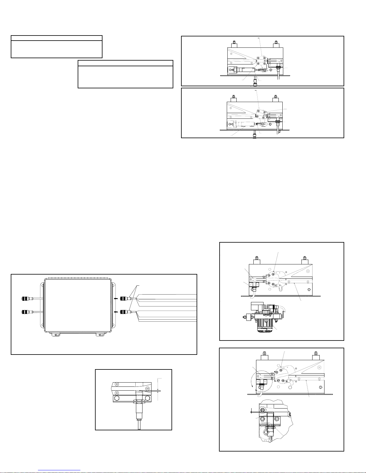
HIGH-SPEED SOLENOID AIR VALVE
The solenoid air valve is used to receive the smart prox output signal and provide
air to the proper end of the divert switch cylinder to move and hold the switch in
either the “home” or “divert” positions. The valve used is specially designed for the
high speed operation necessary for proper divert switch timing.
The two inputs of the solenoid are non-polarized, allowing either lead to be used
as input or ground for the valve. The solenoid requires 24VDC, 6W to operate.
The solenoid air valve is controlled directly by the smart prox. Direct control of this
valve by the controls package is not required or advised.
Other Control Components Supplied with the Conveyor
VARIABLE FREQUENCY DRIVE CONTROLLER
The variable frequency drive (VFD) is a motor controller that has three functions:
1. It provides a smooth acceleration of the drive motor, allowing the sorter to slowly
“ramp up” to full speed. This protects the sorter components from the stress of a
full-speed start up.
2. It allows the speed of the sorter to be adjusted to match speed requirements of
the system. Also, it allows the sorter to be operated at a very slow speed during
installation “Debugging” and when certain mechanical components are checked
after servicing.
3. It allows the sorter to be operated at a slower speed during “off-peak” seasons,
reducing energy consumption, noise, and wear.
Refer to the VFD manufacturer’s installation manual, provided with the sorter, for
wiring and adjustment instructions.
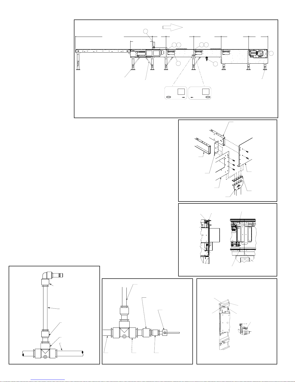
AIR PRESSURE SWITCH
The air pressure switch (Fig. 4E) is used to detect low operating air pressure.
Operation of the sorter at air pressures under 50 PSI can cause erratic switching
and potential switch damage. If air pressure falls below this level, the sorter must
be shut down until the cause of the pressure drop has been found and remedied.
The pressure switch provides a contact-type output which closes at pressures at
or above about 48 PSI and opens below that air pressure. The system controls
provider should use this switch to monitor air pressure at the sorter and should
shut down the sorter if an open (low) output is detected from the pressure switch.
Refer to the pressure switch manufacturer’s installation manual, provided with the
sorter, for wiring instructions.
SAFETY PROXIMITY SWITCHES
There are safety switch devices located at various locations in the sorter to indicate
when a divert shoe is out of place, an obstruction has entered the sorter, or when
some other event has occurred that could cause damage to the sorter or danger to
personnel. These safety switches use normal inductive proximity switches as the
electrical interface to the system controls.
There are two types of safety switches in the sorter:
1. Shoe position safety switches are switch mechanisms inside the sorter that trip
if a divert shoe passes them that is not in its proper track. They are also used to
detect foreign objects that might fall between the slats and enter the interior of the
sorter. They are made to detect problems on both the upper and return portions
of the sorter.
There is one shoe position safety switch located at the infeed end and one at the
discharge end of the sorter. There are additional switches included for every 30 feet
of sorter length after the first 30 feet. For example, a sorter 50 feet long will have a
total of 3 switches, a sorter 80 feet long will have a total of 4 switches and so on.
These additional switches are spaced evenly along the sorter’s length.
2. The transition safety switch is used to detect when the transition assembly on
the discharge end of the sorter is pushed out of position if a stray divert shoe or a
foreign object makes contact with them.
The normal state of the output of the safety proximity switch is”on” (high). If a switch
detects a problem the signal is changed to “off” (low). The system controls must be
configured to go to an “emergency stop” condition and shut down the sorter and
related equipment when a problem is detected. Restart must not be possible until
the problem is corrected and the safety switch that detected the problem is again
“on” (high).
Refer to the proximity switch manufacturer’s installation manual, provided with the
sorter, for wiring instructions.
CATENARY TAKE-UP PHOTO EYE
The catenary take-up photo-eye monitors the amount of chain sag occurring in
the drive’s catenary area. The photo-eye is a retro-reflective, light-operated type,
positioned in the catenary so that if the carrying chains allow the slats to sag below
a certain level, the beam of the eye is blocked.
The system controls must be configured to stop the sorter when the photo-eye
beam is continuously blocked (photo-eye output is “off” or “low”) and provide an
indication to the sorter operator that the chains must be taken up or shortened
before operating the sorter further.
Refer to the photo-eye manufacturer’s installation manual, provided with the sorter,
for wiring instructions.
ENCODER
An encoder is included with the sorter to provide a pulse signal to be used for
product tracking. The encoder provides a square-wave pulse signal of 30 pulses
per revolution of the sorter infeed shaft. This equates to one pulse for every 1.301
inches of sorter travel.
The encoder requires 24VDC power, and provides a 24VDC pulse output.
Refer to the encoder manufacturer’s installation manual provided with the sorter,
for wiring instructions.
CHAIN OILER SOLENOID
The chain oiler is used to provide automatic lubrication of the carrying chains
during sorter operation. When the oiler solenoid valve is energized, oil is allowed
to gravity feed from the oiler reservoir, through metering valves, to brushes located
above the return chains in the sorter.
The system controls should be configured to activate the chain oiler solenoid for a
duration equal to one complete revolution of the carrying chains about every forty
hours of operation. The actual amount of oil applied to the chains is controlled by
the metering screws (see “Conveyor Set-up” section of this manual). The chain
oiler solenoid requires 24VDC power to operate.
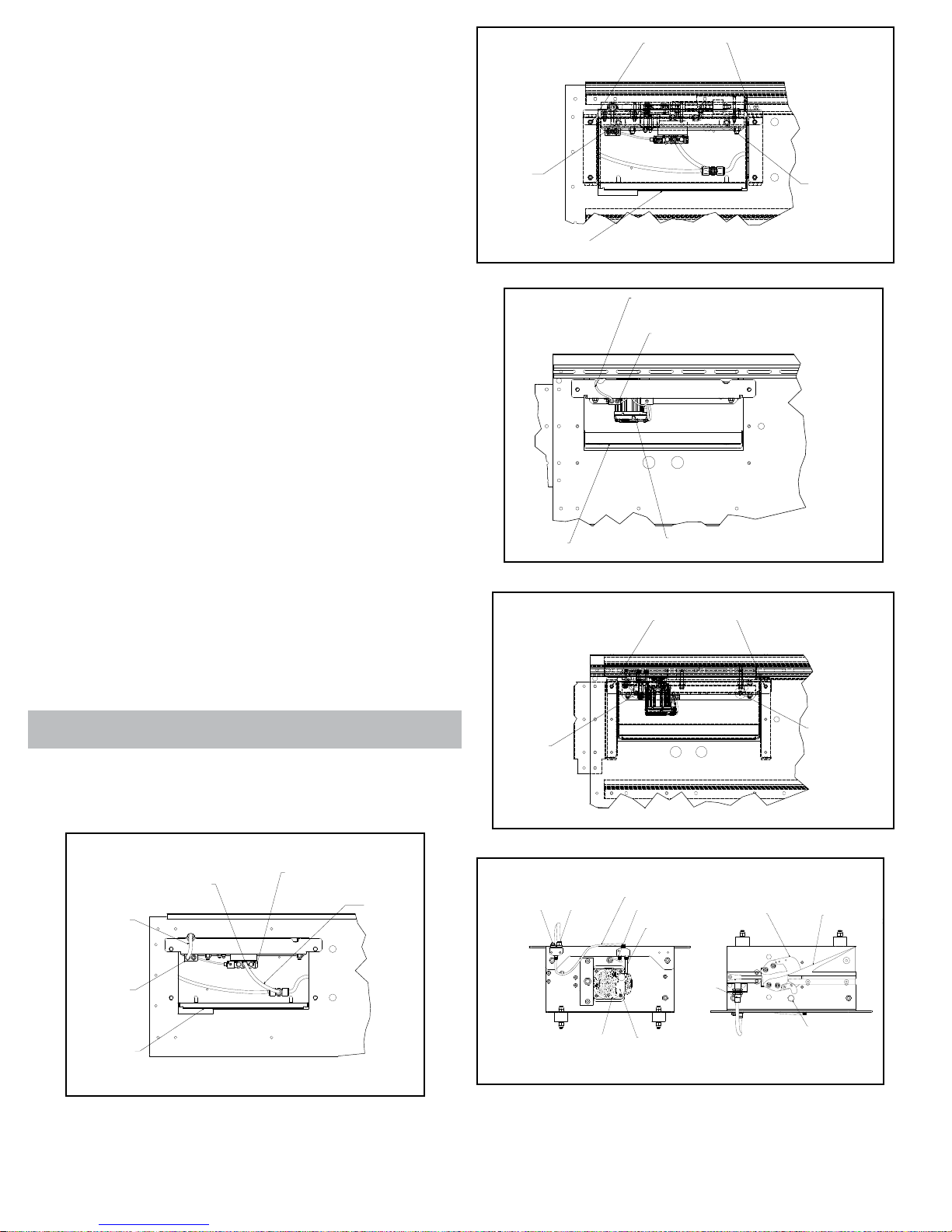
LOST BEARING DETECTION
The missing bearing block is used to detect a bearing missing from a divert shoe.
A divert shoe that does not have a bearing on the bottom can cause damage to
the sorter. The missing bearing block uses two proximity switches located in the
return section of the sorter to detect the presence of a bearing on the shoe. If one
prox detects a bearing being present but the other does not, the block removes its
output to indicate a missing bearing was detected. Missing bearing prox is located
in the bottom of the discharge divert section. The missing bearing detector has a
normally high signal that will output 24 Volts DC as long as no missing bearings/
pins are detected. If a missing bearing/pin is detected then the signal will go low
and the PLC should stop the sorter. Prior to restarting the sorter, the PLC should
pulse 24VDC to the RESET ERROR input on the missing bearing detector. Doing
this will reset the detector so that the output turns back to on.
The missing bearing detector also has the optional feature of testing for the
proper function of the prox sensors used by the detector. The detector has a
second output (BROKEN PROX ERROR) that is normally high (24 VDC) while
the sensors are functioning normally. This output is activated by a SORTER
RUNNING INPUT to the detector. If a signal (24 VDC) is supplied to that input
while the sorter VFD is enabled it will activate the test to detect a malfunctioning
prox sensor. The SORTER RUNNING INPUT must remain energized for the
BROKEN PROX ERROR OUTPUT to be energized as well as to continue testing
the prox sensors. If a malfunctioning prox sensor is detected then the prox
sensors and all connections to the sensors should be inspected and repaired or
replaced. The BROKEN PROX ERROR should be reset in the same manor to that
of the missing bearing error.
The power to operate the missing bearing detector, the prox sensors, and the
signals going back to the PLC are all from a customer supplied 24 VDC source.
The 24VDC, 200 mA power required is to be provided through the M12 connector
labeled ‘INPUT’.
Control Components Not Supplied with the Conveyor
In addition to the control components supplied with the ProSort sorter, there are
several components that must be supplied by the system control provider. Hytrol
recommends the following control components be used to protect the sorter from
damage due to product jams or other problems.
ADJUSTABLE INSTANTANEOUS MOTOR OVERLOADS
Instantaneous overloads provide protection against sorter “hang-ups” by turning
off the drive if a sudden increase in motor current is detected. By adjusting the
overload limit to slightly above the power required to operate the sorter, any
extra load on the motor, such as would be caused by a product jam or switch
malfunction, would cause the sorter to stop, possibly before significant damage is
done to the equipment.
The instantaneous overloads should be installed in the control panel for the sorter
and sized for the proper power requirements.
PHOTO-EYES
Photo-eyes are common components in systems controls. Hytrol recommends that
photo-eyes be installed at the following locations to perform listed functions. These
are, of course, in addition to other photo-eyes needed in the system.
Induction Photo-eye—A photo-eye mounted at the infeed point of the sorter. This
eye is used to perform the following functions:
1. Signal the system controls that a particular package has entered the sorter.
From this point forward, the package must be tracked using the encoder pulses to
determine when it reaches the proper divert location.
2. Measure the length of the package so that the system controls may assign the
proper number of divert shoes to the package for diverting. Note: Shoes are to be
assigned for the entire length of the package plus one extra shoe is to be assigned
to the trailing end of the package.
3. Check for the proper gap between packages for safe sorting. It is important to
check for the proper gap here, even if it has been set prior to this point, to insure
7

that the packages are truly spaced properly. Attempting to sort packages with too
little gap between them can cause jams.
Note: The minimum gap necessary for sorting a package is a function of the width
of the package. The charts below should be used in checking for proper gap.
* W = Maximum Package Width
Note: When sorting to both
sides, the minimum gap from the
above charts must be increased
by 3 in.
Jam/Confirmation Photo-eye—Photo-eyes mounted on each take-away spur of
the sorter, as close to the sorter as possible. These eyes perform two functions:
1. Detect a product jam at the sorter “exit point.” If a package blocks this photo-eye
for a longer time than it would take for the package to travel past the photo-eye
normally, this indicated that the package is jammed. The sorter should be stopped
and the jam cleared before restarting the sorter.
2. Divert confirmation. If a divert signal is given to a particular divert point, and no
package is detected by the associated jam/confirmation photo-eye, an error has
occurred. The sorter should be stopped and the error found and corrected before
restarting the sorter.
Full Line Photo-eye—Photo-eyes mounted on each divert lane from the sorter,
near the infeed end of that lane. These eyes are used to signal the system controls
that a particular divert lane is full. The controls should then send any further
packages assigned to that lane to the recirculation line until the full line photo-eye
on that lane no longer indicates the full condition.
Recommended Controls Procedures
The following are recommendations to assist in the design and installation of
system controls that are interfacing with ProSort sorters.
• Do not place 24VDC control wires in the same wireway with AC power wires,
especially if theAC power exceeds 240 volts. “Noise” produced in the control wires
by the power wires may produce undesirable effects.
• Do not use optional “standard prox output” of the smart prox as a substitute for
an encoder. The five inch spacing between divert shoes does not provide enough
tracking resolution to accurately sort packages.
• Do not use manual override operator of the solenoid air valve to operate a divert
switch while the sorter is running. Doing so bypasses the switch timing controls and
may cause switch damage or a sorter crash.
• Do treat the tripping of any safety switch, motor overload, or low air pressure
signal as an emergency stop. Inspect the safety switch and other parts of the
sorter to be sure everything is in good working order before starting or restarting
the sorter.
• Pneumatic Divert
Switch Checklist
After all ProSort sections are installed
and aligned, each divert switch should be
checked for proper operations as follows:
1. Before air pressure is supplied to the
divert switch solenoid air valve, manually
pivot the switch back and forth between
the non-divert and divert position
checking for a free and smooth pivoting
movement. Determine and remedy the
cause of any switch binding. For proper switch alignment see figures 8C & 8D.
If switch adjustment is necessary, loosen the jam nut on the cylinder rod. Screw
cylinder rod into or out of rod end to adjust the switch and retighten jam nut.
2. Turn air pressure on and verify that each divert switch is in, or moves to, the
home (non-divert) position (Figure 8C).
3. Check to insure that the smart prox is set properly. The face of the prox should
be set just out of the shoe pin guide path in the switch guide (Figure 8B)
•Electric Divert Switch Checklist
NOTE: All electric divert servo motors are paired with the associated drives at the
factory. Connecting motors to the wrong drive may have an adverse effect on the
divert operation and could result in physical damage to the sorter. Always connect
the drives to the factory paired motors to prevent damage.
1. Before running the sorter, apply power to the electric switch system and verify
that the diverts are fully in either the home or diverted position. Divert function was
tested at the factory to ensure proper operation. If the diverts are in the diverted
position, they can be returned to the home position, Figure 8E by removing the
enable signal to the Smart Prox and then flagging the Smart Prox to trigger a
move operation.
2. Each time diverts are powered on, the diverter will move slowly until it finds the
home position.
3. Ensure that the “All Systems Go” signal is on before running the sorter.
4. Check to ensure that the Smart Prox is set properly. The face of the prox should
be set just out of the shoe pin guide path in the switch guide (Figure 8F).
SWITCH BLOCK
(INTERRUPTOR DE
BLOQUEO)
ROD END
(EXTREMO DEL EJE)
NON-DIVERT POSITION
(POSICION DESVIADORA) AIR CYLINDER EXTENDER
(EXTREMO DEL EJE)
SWITCH BLOCK
(INTERRUPTOR DE
BLOQUEO)
ROD END
(EXTREMO DEL EJE)
DIVERT POSITION
(POSICION DESVIADORA)
AIR RETRACTED
(EXTREMO DEL EJE)
JAM NUT
(CONTRA TUERCA)
FIGURE 8D
* BROKEN PROX OUTPUT IS ONLY ACTIVE WHEN SORTER RUN INPUT IS ACTIVE.
BROWN/CAFÉ NOT USED
BLACK/NEGRO
OUPUT (24V=OK, 0V=MISSING BEARING DETECTED)
SALIDA (24 V = CORRECTO, 0 V = COJINETE FALTANTE DETECTADO)
BLUE/AZUL COMMON/COMÚN
WHITE/BLANCO BROKEN PROX ERROR (24=OK, 0V=ERROR)/
ERROR DE SENSOR DE PROXIMIDAD DAÑADO (24 = CORRECTO, 0 V = ERROR)
BROWN/CAFÉ POWER (+24VDC)/ENERGÍA (+24 V CC)
BLACK/NEGRO RESET ERROR INPUT/
ENTRADA DE ERROR DE RESTABLECIMIENTO
BLUE/AZUL COMMON/COMÚN
WHITE/BLANCO SORTER RUNNING INPUT (SORTER UP TO SPEED)
ENTRADA DE CLASIFICADOR EN FUNCIONAMIENTO
(CLASIFICADOR A VELOCIDAD NORMAL)
941.423003
OUTPUT
INPUT
TO PROX 2
TO PROX 1
(HACIA SENSOR DE
PROXIMIDAD 1)
(HACIA SENSOR DE
PROXIMIDAD 2)
(SALIDA)
(ENTRADA)
(LA SALIDA DE SENSOR DE PROXIMIDAD DAÑADO SOLO SE ACTIVA CUANDO LA
ENTRADA DE FUNCIONAMIENTO DEL CLASIFICADOR ESTÁ ACTIVA.)
FIGURE 8A
FIGURE 8C
1/32"
FIGURE 8B
V
V
NON-DIVERT POSITION
SERVO MOTOR
DIVERT BLOCK
PROX SWITCH
SWITCH GUIDE
NON-DIVERT POSITION
(POSICIÓN SIN DESVIACIÓN)
(GUÍA DEL
INTERRUPTOR)
(INTERRUPTOR
DE PROXIMIDAD)
(BLOQUE DE DESVIACIÓN)
(POSICIÓN SIN DESVIACIÓN)
(SERVOMOTOR)
FIGURE 8E
U
DIVERT POSITION
DIVERT BLOCK
SWITCH GUIDE
SWITCH BLOCK
PROX SWTICH
DETAIL U
SCALE 1.50 : 1
1/32
(BLOQUE DEL
INTERRUPTOR)
(GUÍA DEL
INTERRUPTOR)
(INTERRUPTOR
DE PROXIMIDAD)
(BLOQUE DE
DESVIACIÓN)
(POSICIÓN DE
DESVIACIÓN)
(DETALLE U)
(ESCALA 1.50: 1)
FIGURE 8F
ProSort 121 (22° Diverts)
0” < W ² 6” Minimum gap = 6”
6” < W ² 18” Minimum gap = 9”
18” < W ² 30” Minimum gap = 12”
ProSort 131 (30° Diverts)
0” < W ² 6” Minimum gap = 6”
6” < W ² 12” Minimum gap = 9”
12” < W ² 18” Minimum gap = 12”
18” < W ² 24” Minimum gap = 15”
8

• Carrying Chain Installation
The carrying chains are shipped on marked spools, cut to proper length for each
ProSort conveyor. Steps for installing are as follows:
1. Disconnect electrical power to drive motor to prevent accidental start up.
2. Check alignment of chain guides by using two short pieces of chain with slat/
shoe assemblies and bearings assembled to pins. This chain/slat/shoe assembly
should slide freely through chain guides in direction of travel for entire length of
conveyor.
3. Install carrying chains to both sides of conveyor with pins pointed inward
(Figure 9C). Make sure the pins of each chain are directly opposite each other.
Bearings with bushings are installed on each pin. It will be helpful while installing
chains to install one slat/shoe assembly every 4 feet to hold chain in guides.
4. Fasten ends of both chains with connector links as shown in Figure 9B. Follow
manufacturer’s instruction on proper lubrication when installing connector links.
5. Install slat/shoe assemblies onto the extended chain pins on one side of
conveyor – being careful to keep the beveled face of the shoe toward the discharge
end and the side with the rubber insert toward the spur side of conveyor (See
Figure 9B). Lift opposite chain out of chain guide (so chains may be spread apart)
and insert extended chain pins into opposite end of slat/shoe assemblies.
6. After all slat/shoe assemblies are installed, tighten carrying chains with take-up
bolts at drive shaft. Be sure drive and tail shafts are square. Retighten all drive
take-up plate mounting bolts. See Figure 9A for proper slack in chains.
7. Manually crank entire carrying chain assembly through the conveyor to see
that it operates freely and nothing has been dropped into the conveyor during
installation. Also inspect divert shoes to make sure all of them have been installed
on the correct centers. If chains are ever shortened it must be in increments of
three inches.
8. Reconnect electrical power to drive motor.
•InstallGuardRailsatDivertLocations
If guard rails are to be installed on the spurs and/or the spur side of the sorter,
care should be taken to insure that the guard rails do not interfere in any way with
the boxes being diverted. Particularly, guards should not be installed in a way that
produces a sharp edge or point in the divert area.
• Locating the Spurs
The take-away spurs must be mounted properly on the divert sections of the
ProSort to insure proper diverting of product. The following installation guidelines
apply to both powered and gravity spurs.
1. Attach spurs to the sorter by bolting the spur attachment bracket to the spur
mounting nuts in the unistrut channel on the sorter side channel (Figure 9D).
Support the spurs as required. Hand-tighten bolts only at this time.
2. Manually place 3 or more shoes along the divert angle as shown. Place a
straight-edge against the shoes to determine the location of the “divert line”. Verify
that the distance between the “divert line” and the “BR” of the spur is at least 1-1/4”
as shown (Figure 9E).
3. Position spur vertically so that the spur rollers/skatewheels are level with the
slats on the sorter. Tighten mounting bolts.
4. Jackbolt Assembly supplied with spur.
ALLOW FROM 5” TO 6” AT INSTALLATION
(PERMITA DE 5 A6 PULGADAS DE ESPACIO
DURANTE LA INSTALACION)
FIGURE 9A
CARRYING CHAIN
(CADENA)
SPRING CLIP
(CADENA)
COVER PLATE
(CADENA)
O-RINGS
(CADENA)
CONNECTOR LINK
(CADENA)
BEARING
(CADENA)
SLAT
(CADENA)
BUSHING
(CADENA)
FIGURE 9B
FLOW
(FLUJO)
FIGURE 9C
SPUR PLATE
(PLACA DE LA
ESPUELA)
SPUR ATTACHMENT
BRACKET
(BRAZO SOPORTE
DE LA ESPUELA)
UNISTRUT
(CANAL)
FIGURE 9D
DIVERT LINE
(LINEADESVIADORA) 1-1/4" Minimum
(1-1/4" como mínimo)
FIGURE 9E
9

• Pneumatic Divert Switch Removal
Procedure
The ProSort is designed for easy removal of the divert switch assembly for
maintenance or replacement. In order to remove the pneumatic switch assembly
follow the following steps.
1. Unplug the elbow from the fitting on the solenoid air valve by pushing in the red
flange of the fitting and then pulling on the elbow.
2. Disconnect prox switch cord set from y-cable connector (Figure 6A).
3. Remove the cover located on the side of the sorter under the divert switch
assembly by lifting and rotating down and out of the way (Figure 10B).
4. By reaching through the uncovered hole in the side channel remove the two nuts
at the back side of the switch assembly channel. Then remove the two bolts on the
outside of the sorter channel which hold up the front side of the switch assembly
channel (Figure 10B).
5. The front side of the switch assembly channel may then be lowered and the entire
assembly may be removed through the opening in the sorter channel.
6. Check the new switch assembly according to the “Divert Switch Checklist” on
page 8.
7. Install the new divert switch assembly by reversing the procedure by which the old
assembly was removed.
• Electric Divert Switch Removal Procedure
The ProSort is designed for easy removal of the divert switch assembly for
maintenance or replacement. In order to remove the electric switch assembly follow
the following steps.
1. Turn off all power going into the panel connected to the divert that is needing to be
removed. This includes turning the disconnect on the front of the panel to the OFF
position and disconnecting the 3-Phase supply power and control power.
2. Wait at least 90 seconds after removing all power to allow the power to fully
dissipate to a safe level.
3. After waiting 90 seconds, remove the cover located on the side of the sorter under
the divert switch assembly by lifting and rotating down and out of the way. Remove
the 5-wire M12 cable and black power cable from the splitter cable.
4. By reaching through the uncovered hole in the side channel, remove the two nuts
at the back side of the switch assembly channel. Then remove the two bolts on the
outside of the sorter channel which hold up the front side of the switch assembly
channel (Figure 10D).
5. The front side of the switch assembly channel may then be lowered and the entire
assembly may be removed through the opening in the sorter channel.
• Electric Switch Homing Procedure
1.Before starting the sorter, supply 24VDC power to homing prox and Smart prox.
2.Supply 48VDC to the servo motor (Figure 10E).
3.The servo motor goes through a homing procedure where the switch block rotates
to find the home location. This process takes approximately 10 seconds to complete.
4.Wait for the enable signal from the switch.
5.Sorter is now ready to run.
REMOVE
LOCK NUTS
(REMUEVA
LAS TUERCAS)
REMOVE
LOCK NUTS
(REMUEVA
LAS TUERCAS)
REMOVE BOLTS
(REMOVER
LOS TORNILLOS)
COVER
(CUBIERTA)
FIGURE 10B
REMOVE
LOCK NUTS
(REMUEVA
LAS TUERCAS)
REMOVE
LOCK NUTS
(REMUEVA
LAS TUERCAS)
REMOVE BOLTS
(REMOVER
LOS TORNILLOS)
FIGURE 10D
COVER
PROX SWITCH
CORD
Y-CABLE
AIR LINE FITTING SOLENOID AIR VALVE
AIR LINE
(CUBIERTA)
(CABLE Y)
(CABLE DEL
INTERRUPTOR
DE PROXIMIDAD)
(TUBERÍA
DE AIRE)
(VÁLVULA DE AIRE SOLENOIDE)
(ACCESORIO DE LA
TUBERÍA DE AIRE)
FIGURE 10A
COVER
(CUBIERTA)
SERVO MOTOR
SPLITTER CABLE
PROX SWITCH CORD
(SERVOMOTOR)
(CABLE DIVISOR)
(CABLE DEL INTERRUPTOR DE PROXIMIDAD)
FIGURE 10C
WARNING! Keep ngers clear of switch blcok during the homing procedure.
BOTTOM VIEW TOP VIEW
SWITCH BLOCK DIVERT BLOCK
HOMING PROX
SMART PROX
CUSTOMER SUPPLIED
24VDC SMART PROX
CONNECTION
SERVO I/O SPLITTER CABLE
I/O TO SERVO MOTOR
TO HOMING PROX
SERVO MOTOR HYTROL SUPPLIED
48VDC
(24 V CC PROPORCIONADA
POR EL CLIENTE) (CONEXIÓN DE
SMART PROX)
(CABLE DIVISOR DE E/S SERVO)
(HACIA SENSOR DE PROXIMIDAD
DE AUTODIRECCIÓN)
(E/S HACIA SERVOMOTOR)
(BLOQUE DEL
INTERRUPTOR )
(BLOQUE DE DESVIACIÓN)
(SENSOR DE PROXIMIDAD
DE AUTODIRECCIÓN)
(48 V CC PROPORCIONADA
POR HYTROL)
(SERVOMOTOR)
(VISTA INFERIOR ) (VISTA SUPERIOR)
FIGURE 10E
10

• Trouble Shooting
The following charts list possible problems that may occur in the operation of the ProSort.
TROUBLE SHOOTING DRIVES
TROUBLE CAUSE SOLUTION
Conveyor will not start or shuts off
automatically during operation.
1) Jam eye blocked
2) Tripped internal safety switch.
3) Transition rollers out of position.
4) Proximity switch for internal safety switch or transition rollers
mis-adjusted or defective.
5) Low air pressure.
a) Regular set low.
b) Air line restricted or broken.
c) Air lter clogged.
d) Compressor problem.
e) Lockout closed.
6) Electrical circuits.
7) Variable speed drive mis-adjusted or defective.
8) Drive motor defective.
1) Unblock jam eye.
2) Determine cause of tripping: foreign debris, mislocated divert
shoes, etc., and correct problem.
3) Determine reason for transition rollers being out of position and
correct problem.
4) Adjust or replace proximity switch.
5) Determine reason for low air pressure and correct problem.
6) Check power and wiring.
7) Refer to variable speed drive manufacturer’s manual for trouble
shooting.
8) Replace motor.
Conveyor takes long time to reach
speed or conveyor jerks when starting. 1) Variable speed drive mis-adjusted or defective. 1) Refer to variable speed drive manufacturer’s manual for trouble
shooting.
Divert shoes "jump" during diverting.
1) Divert shoe tight on slats.
2) Slats dirty.
3) Slats bent.
4) Switch mis-adjusted.
1) Replace slat/shoe assembly.
2) Clean surface. (Refer to Preventive Maintenance Details)
3) Replace slat/shoe assembly.
4) Refer to Divert Switch Checklist, Page 8 & 9.
Inoperative divert switch.
1) No air pressure to cylinder.
2) Lockout closed.
3) Air solenoid valve defective.
4) Proximity switch mis-adjusted or defective.
1) Check air line and filter regulator. Replace if necessary.
2) Open lockout.
3) Replace.
4) See page 8 & 9 for proper adjust or replace.
All divert switches inoperative. 1) Loss of power to air solenoid valves.
2) Controls failure. 1) Correct problem.
2) Trouble shoot control system.
Inoperative electric divert switch 1) No power to electric switch. 1) Check 3-Phase power to the servo drive enclosure.
30° LOST PIN PROX ASSEMBLY
22° LOST PIN PROX ASSEMBLY
1
4
2
1
2
3
3
6 9
4
6
10
7
8
7
8
69
610
Ref.
No. Part No. Description
1
2
3
4
-
-
941.650185
923.0227
-
092.1793
Y-Block Support Plate - Return (22° or 30°)
Prox Switch - 18MM
Fixing Clamp
-
Y-Block - LH, 22° Return
-
-
-
5
6
092.1783
092.17955
092.17855
EB-000068
041.800
Y-Block - RH, 22° Return
Y-Block - LH, 30° Return
Y-Block - RH, 30° Return
Missing Bearing Detection Controller
1/4-20 Hex Locknut - Nylon Insert
7
8
9
10
041.801
042.10234
042.654
042.6545
#8-32 Hex Locknut - Nylon Insert
#8-32 x 1-3/4 in. lg Round Head Machine Screw
1/4-20 x 2 in. lg Hex Socket Flat Head Cap Screw
1/4-20 x 2-1/2 in. lg Hex Socket Flat Head Cap Screw
Lost Pin Prox Assembly
Conjunto de sensor de proximidad de pasador perdido
11

LEFT-HANDED 22° SWITCH ASSEMBLY
SA-067120
TORQUE NUT
TO 225 IN-LB.
TORQUE BOLT TO 110 IN-LB.
TO PLATE.
8
39
20 16 22
38
12
14 23
10
17
12
10
8
43
20
35
9
37
36
28
1
7
44
8
20
3
34
14
4
21
41
40
27 26
42
27
32
33
24 25 29 30
31
15
2
A
20
21
12
4
3
39
40
34
20
44 728 36
36 9
8
43
37
18
20
35
8
23
22
12
8
LEFT-HAND 30° PNEUMATIC
SWITCH SHOWN SA-061764
27 32
39
11
2
TORQUE NUT
TO 225 IN-LB.
41
1
6
5
19
44
6
TORQUE BOLT
TO 110 IN-LB.
26
27
10
10
17
13
31
33
TORQUE NUT
TO 48 IN-LB.
LOCTITE
POSITIONING
STUD TO
CYLINDER WITH
271 LOCTITE
14
14
37
25
29
24
30
12
15
• Pneumatic Divert Switch Assembly Parts Drawing
Dibujo de piezas del conjunto de interruptor de desviación neumático
Ref.
No. Part No. Description
1
2
3
4
5
019.222
032.21124
032.2113
040.100
040.20255
Female Rod End - 5/16-24 RH Threads
Y-Plug Cable Connector
Smart Proximity Switch-24VDC, Customized
1/4-20 X 3/4 in. LG Hex Head Cap Screw, ZP
5/16-24 X 1-1/4 in. LG Hex Bolt, Full TH, GR 8
6
7
8
9
10
041.1012
041.596
041.798
041.799
041.800
5/16-24 Hex Nut - Grade 8, Yellow Zinc
5/16-24 NC2B Hex 2-WAY Jam Locknut- REG,
3/8-16 NC2B Hex Locknut- Nylon Insert, ZP
5/16-18 NC2B Hex Locknut-Nylon Insert, ZP
1/4-20 NC2B Hex Locknut-Nylon Insert, ZP
11
12
13
14
15
041.8005
041.802
042.59025
042.651
042.6515
#6-32 Hex Locknut - Nylon Insert, ZP
#10-24 NC2B Hex Locknut- Nylon Insert, ZP
#6-32 X 1-1/4 in. LG Socket Head Mach Screw
#10-24 X 1 in. LG Hex Skt Flat HD Cap Screw
#10-24 X 1-3/4 in. LG Hex Skt Flt HD Cap Screw
16
17
18
19
20
042.6535
042.654
042.6545
043.300
092.163
1/4-20 X 1-3/4 in. LG Hex Skt Flt HD Cap Screw
1/4-20 X 2 in. LG Hex Skt Flt HD Cap Screw
1/4-20 X 2-1/2 in. LG Hex Skt Flt HD Cap Screw
5/16 in. ID External Lockwasher, ZP
Rubber Vibration Mount - 1-1/2 in. DIA
21
22
23
-
24
092.1825
MP-002574
092.184905
092.184906
094.107955
Switch Guide - ProSort 100
Switch Block - PS100E
Divert Block - LH, 30 DEG, PS100E
Divert Block - RH, 30 DEG, PS100E
4-Way Single Solair Valve - 24VDC
25
26
27
28
29
094.10816
094.1149
094.11496
094.12021
094.140
1/8 in. Porous Bronze Mufer
3/8 in. OD Polyurethane Tubing - Black
1/2 in. OD Polyurethan Tubing - Black
Air Cylinder - 9/16 in. Stroke, 20MM Bore
Brass Conn-Straight Male,1/4 in. PLST-1/8 in. NP
30
31
32
33
34
094.14015
094.1406
094.14089
094.1465
911.0264
Brass Conn-Straight Male, 1/8 in. NPT-3/8 in. PLS
Plastic Elbow - Male, 360D Swivel W/RET
Plastic Tee-1/2 in. PLST-1/2 in. PLST-1/2 in. PLST
Plug-In Reducer - 3/8 in. PLST-1/2 in. Push-In
M18 Internal Tooth Lockwasher, ZP
35
36
37
38
39
923.0172
923.0173
043.101
MP-002541
-
Positioning Stud - 5/16 in. -18 X 2-1/2 in. LG
Urethane Bushing
5/16 in. ID Flat Steel Washer
Switch Bearing Block - Nylon, ProSort 100
Switch CHNL - PS100E (LH or RH)
40
41
42
43
44
-
-
-
-
-
PROX SWITCH MOUNTING ANGLE - PS100E
SWITCH MOUNTING ANGLE - PS100E
VALVE MOUNTING ANGLE - INSIDE AIRLINE
CYLINDER MTG ANGLE - BUSHING
SWITCH PLATE WELD -(LH or RH)
Ref.
No. Part No. Description
1
2
3
4
5
019.222
032.21124
032.2113
040.100
040.20255
FEMALE ROD END - 5/16-24 RH THREADS
Y-PLUG CABLE CONNECTOR
SMART PROXIMITY SWITCH-24VDC, CUSTOMIZED
1/4-20 X 3/4"LG HEX HEAD CAP SCREW, ZP
5/16-24 X 1-1/4"LG HEX BOLT,FULL TH,GR 8
6
7
8
9
10
041.1012
041.596
041.798
041.799
041.800
5/16-24 HEX NUT - GRADE 8, YELLOW ZINC
5/16-24 NC2B HEX 2-WAY JAM LOCKNUT- REG,
3/8-16 NC2B HEX LOCKNUT- NYLON INSERT,ZP
5/16-18 NC2B HEX LOCKNUT-NYLON INSERT,ZP
1/4-20 NC2B HEX LOCKNUT -NYLON INSERT,ZP
11
12
13
14
15
041.8005
041.802
042.59025
042.651
042.6515
#6-32 HEX LOCKNUT - NYLON INSERT, ZP
#10-24 NC2B HEX LOCKNUT- NYLON INSERT,ZP
#6-32 X 1-1/4"LG SOCKET HEAD MACH SCREW
#10-24 X 1"LG HEX SKT FLAT HD CAP SCR
#10-24 X 1-3/4"LG HEX SKT FLT HD CAP SCR
16
17
18
19
20
042.6535
042.654
042.6545
043.300
092.163
1/4-20 X 1-3/4"LG HEX SKT FLT HD CAP SCR
1/4-20 X 2"LG HEX SKT FLT HD CAP SCR
1/4-20 X 2-1/2"LG HEX SKT FLT HD CAP SCR
5/16"ID EXTERNAL LOCKWASHER, ZP
RUBBER VIBRATION MOUNT - 1-1/2"DIA
21
22
23
-
24
092.1825
MP-002574
092.184903
092.184904
094.107955
SWITCH GUIDE - PROSORT 100
SWITCH BLOCK - PS100E
DIVERT BLOCK - LH, 20 DEG, PS100E
DIVERT BLOCK - RH, 20 DEG, PS100E
4-WAY SINGLE SOLAIR VALVE - 24VDC
25
26
27
28
29
094.10816
094.1149
094.11496
094.12021
094.140
1/8” POROUS BRONZE MUFFLER
3/8”OD Polyurethane Tubing - Black
1/2” OD Polyurethan Tubing - Black
AIR CYLINDER - 9/16”STROKE, 20MM BORE
BRASS CONN-STRAIGHT MALE,1/4”PLST-1/8”NP
30
31
32
33
34
094.14015
094.1406
094.14089
094.1465
911.0264
BRASS CONN-STRAIGHT MALE,1/8”NPT-3/8”PLS
PLASTIC ELBOW - MALE, 360D SWIVEL W/RET
PLASTIC TEE-1/2”PLST-1/2”PLST-1/2”PLST
PLUG-IN REDUCER - 3/8”PLST-1/2”PUSH-IN
M18 INTERNAL TOOTH LOCKWASHER, ZP
35
36
37
38
39
923.0172
923.0173
043.101
MP-002541
-
POSITIONING STUD - 5/16”-18 X 2-1/2”LG
URETHANE BUSHING
5/16”ID FLAT STEEL WASHER
SWITCH BEARING BLOCK - NYLON,PROSORT 100
SWITCH CHNL - PS100E (LH or RH)
40
41
42
43
44
-
-
-
-
-
PROX SWITCH MOUNTING ANGLE - PS100E
SWITCH MOUNTING ANGLE - PS100E
VALVE MOUNTING ANGLE - INSIDE AIRLINE
CYLINDER MTG ANGLE
SWITCH PLATE WELD -(LH or RH)
12

30° LEFT-HAND ELECTRIC
SWITCH ASSEMBLY SA-071882-L
33
24
24
19
32
27
29
5
32
717
23
18
35
26
11
15
7
1
34
2
10 20
5
19 19
5
21 322 36
9
6
37
4
14
5
16
25
7
13
SAFETY SWITCH ASSEMBLY
SA-063997
110
7
10
925 6
1
3
2
4
8
5
6
Ref. No. Part No. Description
1
2
3
4
5
032.2113
040.100
040.2031
041.796
041.798
Smart Proximity Switch-24VDC, Customized
1/4-20 X 3/4 in. LG Hex Head Cap Screw, ZP
5/16-18 X 2 in. LG Hex Head Cap Screw, ZP
1/2-13 NC2B Hex Locknut- Nylon Insert,ZP
3/8-16 NC2B Hex Locknut- Nylon Insert,ZP
6
7
8
9
10
041.799
041.800
041.8005
041.801
041.802
5/16-18 NC2B Hex Locknut -Nylon Insert,ZP
1/4-20 NC2B Hex Locknut -Nylon Insert,ZP
#6-32 Hex Locknut - Nylon Insert, ZP
#8-32 Hex Locknut - Nylon Insert, ZP
#10-24 NC2B Hex Locknut - Nylon Insert,ZP
11
12
13
14
15
042.10338
042.59025
042.59505
042.6515
042.6535
#8-32 X 3/4 in. LG Round Head Machine Screw,ZP
#6-32 X 1-1/4 in. LG Socket Head Mach Screw
1/4-20 X 2-1/4 in. LG Skt HD Cap Screw,STD THD
#10-24 X 1-3/4 in. LG Hex Skt Flt HD Cap Screw
1/4-20 X 1-3/4 in. LG Hex Skt Flt HD Cap Screw
16
17
18
19
20
042.6545
042.6642
046.061
092.163
092.1825
1/4-20 X 2-1/2 in. LG Hex Skt Flt HD Cap Screw
3/8-16 X 3-1/4 in. LG Hex Skt Flt HD Cap Screw
M5-8MM Hex Locknut - Nylon Insert
Rubber Vibration Mount - 1-1/2 in. DIA
Switch Guide - ProSort 100
21
22
23
24
25
MP-002616
092.18466
092.184907
098.150
923.0220
Switch Bearing -Teknic, Nylon 6/6,PRO 400
Switch Block - Nylatron, ProSort 100E
Divert Block - RH, 30 DEG, PS100E
Spacer - .406 in. ID X .75 in. OD X .375 in. LG
Low Socket Cap Screw - M5-0.8 X 25MM
26
27
28
29
30
941.650184
941.721130
941.721132
941.72133
-
Inductive Prox - 12MM
Servo - Teknic 3421P, ProSort ELEC Switch
Power Cable - ProSort ELEC Switch Servo
Servo I/O Splitter Cable
Spacer Plate - Teknic Servo, 4GA
31
32
33
34
35
-
-
-
-
-
CAM - Teknic Servo, 1-5/8 in. DIA
Switch CHNL ELECT- PS100E (LH)
Switch Mounting Angle - PS100E
Prox Switch Mounting Angle - PS100E
Prox Plate
36
37 -
-Switch Pivot Weld (LH)
M18 Internal Tooth Lockwasher
• Electric Divert Switch Assembly Parts Drawing
Dibujo de piezas del conjunto de interruptor de desviación eléctrico
Ref. No. Part No. Description
1
2
3
4
5
032.2116
040.101
040.1035
041.100
041.800
Prox Switch - DC, Normally Open
1/4-20 x 1" lg. Hex head cap screw
1/4-20 x 1-3/4" lg. Hex head cap screw
1/4-20 Hex Nut
1/4-20 Hex Locknut w/nylon insert
6
7
-
-
-
043.100
-
069.715827
069.715833
069.715839
1/4" I.D. Flat steel washer
Sensor Belt
For 27"OAW
For 33"OAW
For 39"OAW
-
8
9
10
069.715845
090.220
-
-
For 45”OAW
Red Vinyl Plastisol Cap
Safety Switch Plate (specify OAW)
Mounting Bracket (LH or RH)
Safety Switch Assembly
Conjunto de interruptor de seguridad
13

30
RETURN DIVERT
BOTTOM VIEW
(SCALE: NONE)
RETURN DIVERT CATENARY DIVERT DRIVE
56 49 50
54
48
36
56
134
133
132
50
42
49
25 41
47
29
30
32 15 25 136 25
19
21
1
9
14124
18
34
35
38
124
36
3338
124
46 44 33 35 44 39 33 24 13 26
21
20
16
23
6
8
27
22
7
2
10
17
28
4
125
31
37
40
24
11
127126
33
11
11
45
45
39
40
39
40
52
55 43
53
51 12
13
3
5
137 137
• Model ProSort 131 Elite Parts Drawing
Dibujo de piezas del modelo ProSort 131 Elite
Catenary Divert, Return Divert, and Drive Section
(Sección de transmisión, desviación de retorno y desviación catenaria)
14

16
INTERMEDIATE DIVERT
TAIL
62 53
70
71
6
8
58
21
68
60 64 59
69
52 55 34
38
124
61 63
57 74
7273 77 44 33 127 34 35 38 124
3731
39
40
126
128129130
11
45
125
63
45
67
72
76
132131
65
75
66
137
137
• Model ProSort 131 Elite Parts Drawing
Dibujo de piezas del modelo ProSort 131 Elite
Intermediate Divert and Tail Section
(Sección de retorno y desviación intermedia)
NOTE:
Place chain covers so that no
seams are located within the spur/
diverting area.
NOTA:
Coloque las cubiertas de cadena para
que no haya empalmes en el área de
desvío con la espuela.
15

16
6
7
8
9
1
7
3
4
5
4
2
• Model ProSort 131 Elite Parts Drawing
Dibujo de piezas del modelo ProSort 131 Elite
Intermediate Section Assembly
(Conjunto de sección intermedia)
INFEED INDUCTION INDUCTION DRIVE
6 1/2
117 116
119
118 121 122
117 93 86
119120 123
98 85
86
100 94
97 79
89
96
92
84
88
90
85 108
114
95
115
87 107 91 78
111 79
95
102
101
99
107 105
112
106
80 103104 109 110
81
113
82 83
• Model ProSort 131 Elite Parts Drawing
Dibujo de piezas del modelo ProSort 131 Elite
Induction Unit
(Unidad de inducción)
Ref.
No. Part No. Description
1
2
3
4
5
P-01898
P-01899
P-01940
PT-141785
PT-141807
Chain Guide Wearstrip - Top (specify length)
Chain Guide Wearstrip - Bottom (specify length)
Chain Cover (specify length)
Chain Guide Mounting Angle (specify length)
Splice Plate - PS100E
6
7
8
9
PT-142073
P-02389
PT-145205
WA-040365
Pin Guide Spacer
Side Angle (specify length & LH or RH)
Joint Pin Guide Plate
Bed Spacer Weldment (specify OAW)
16

16
34
9
10
9
5
7
20
11
12
18
12
16
3
13
15 1
6
14
17
19
82
20
30° Divert Section
(Sección de desviación de 30°)
Ref.
No. Part No. Description
1
2
3
4
5
092.1785
092.1795
MP-002356
P-01898
P-01899
Y-BLOCK - LH, 30 DEG, PROSORT 100E
Y-BLOCK - RH, 30 DEG, PROSORT 100E
UHMW WEARSTRIP - J-LEG (specify length)
CHAIN GUIDE WEARSTRIP - TOP (specify length)
CHAIN GUIDE WEARSTRIP - BOTTOM (specify length)
6
7
8
9
10
P-01940
PT-141782
PT-141783
-
PT-141807
CHAIN COVER (specify length)
COVER PLATE SWITCH SIDE
COVER PLATE
CHAIN GUIDE MOUNTING ANGLE
SPLICE PLATE - PS100E
11
12
-
-
-
PT-142073
-
-
-
-
PIN GUIDE SPACER
SIDE ANGLE - DIVERT (specify length & LH or RH)
51” long for 27” OAW
60” long for 33” OAW
72” long for 39” OAW
-
13
14
15
16
-
-
PT-141784
-
SA-061764
81" long for 45" OAW
DIVERTANGLE - PS100E
Y-BLOCK SUPPORT PLATE, 30D
WEARSTRIP TIE STRAP
SWITCH ASSY - LH, 30 DEG
17
18
19
20
SA-066648
WA-040365
WA-040366
PT-174779
SWITCH ASSY - RH, 30 DEG
BED SPACER WELD (specify OAW)
SWITCH SUPT CHNL WELD
DIVERT ANGLE ALIGNMENT BLOCK
Alignment Offset
(Compensación de alineación)
Ref.
No. Part No. Description
1 PT-174779 DIVERT ANGLE ALIGNMENT BLOCK
NOTE:
Use the alignment offset tool to make sure that the divert rail is
properly aligned with the divert block.
NOTA:
Use la herramienta de compensación de alineación para garantizar
que el riel de desviación esté correctamente alineado con el bloque
de desviación.
WARNING! If divert rail and divert block are not properly aligned this can create
unwanted noise and potentially cause damage.
¡ADVERTENCIA! Si el riel de desviación y el bloque de desviación no están
correctamente alineados, se puede generar un ruido no deseado y potencialmente
provocar daños.
17

• Model ProSort 131 Elite Parts List
Lista de piezas del modelo ProSort 131 Elite
Ref.
No. Part No. Description
1
2
3
4
5
010.2052
020.150
032.2116
040.409
041.201
Bearing - Cast Iron, 4-bolt, 1-15/16” bore
Sheave - 1A, 8.95”OD X 1-1/2” bore
Proximity Switch
1/2-13 x 6”lg. Hex Bolt, full thread
1/2-13 Hex Jam Nut
6
7
8
9
10
SA-077155
375.03625
932.0187
MP-002368
PT-098832
Cushion Disk Assembly PS100E
O-ring - Orange, 3/8” diameter
Cushion Disk - 3/4” wide X 11-1/8”OD X 1.945” Bore
Chain Guide Wearstrip - Bottom
Belt Brush (specify OAW)
11
12
13
14
15
PT-142073
PT-144001
PT-144126
PT-145273
PT-145274
Pin Guide Spacer
Side Angle- Drive, Inside (LH or RH)
Side Angle- Drive, Outside (LH or RH)
Chain WearstripAngle - Drive
Drive Catenary Wearstrip
16
17
18
19
20
PT-145302
PT-145575
PT-145702
-
PT-152157
End Cover - Drive
Brush Holder - 31-1/2”lg. (LH or RH)
Joint Splice Plate - Drive
Torque Arm Bracket
Drive Shaft (specify OAW)
21
22
23
24
25
SA-063930
SA-066115
SA-068320
WA-040985
WA-040986
Sprocket Assembly
Transition Drive Assembly (specify OAW)
Transition Roller Assembly (specify OAW)
Bed Spacer Weldment (specify OAW)
Bed Spacer Weldment - Catenary, Lower (specify OAW)
26
27
28
29
30
WA-041274
WA-041284
WA-041286
033.2130
033.2131
Drive Bearing Mounting Channel Weldment (LH or RH)
Guard Weldment
Take-up Weldment
Photoeye - Retro-Reective, 10-40VDC
Photoeye Mounting Bracket - Ball Swivel
31
-
-
32
33
-
092.1785
092.1795
MP-002572
MP-002356
Y-Block
Y-Block - LH, 30°
Y-Block - RH, 30°
Catenary Block
UHMW Wearstrip - J-leg (specify length)
34
35
36
37
38
-
-
-
-
-
Chain Guide Wearstrip - Top (specify length)
Chain Cover (specify length x 8)
Cover Plate Switch Side
Y-Block Support Plate
Chain Guide Mounting Angle
39
40
41
42
43
-
-
-
-
-
Divert Angle (specify length)
Wearstrip Tie Strap (specify length)
Catenary Wearstrip
End Plate for Catenary (specify length)
Side Angle - Catenary
-
-
-
-
44
-
-
-
-
-
51 inch long, for 27”OAW 30° (LH or RH)
60 inch long, for 33”OAW 30° (LH or RH)
72 inch long, for 39”OAW 30° (LH or RH)
81 inch long, for 45”OAW 30° (LH or RH)
Pneumatic Switch Assembly
-
-
45
46
47
SA-061764
SA-066648
-
-
-
30 ° Pneumatic Switch Assembly - LH
30° Pneumatic Switch Assembly - RH
Bed Spacer Weldment (specify OAW)
Switch Support Channel Weldment
Photo-eye Channel Weld - Catenary, Lower (specify OAW)
48
49
50
51
52
092.18051
B-23847
MP-002544
-
-
Sweep Block - 30°
Pin Guide Block Plate
Pin Guide
Chain Guide Wearstrip - Bottom
Cover Plate
53
54
55
-
-
-
-
-
-
-
Splice Plate
Y-Block Support Plate, Return
Side Angle - Return Divert
51 inch long, for 27”OAW 30° (LH or RH)
60 inch long, for 33”OAW 30° (LH or RH)
-
-
56
57
58
-
-
SA-073869
MP-002583
095.150
72 inch long, for 39”OAW 30° (LH or RH)
81 inch long, for 45”OAW 30° (LH or RH)
Lost Pin Prox Assembly (22° or 30° & LH or RH)
Infeed Guide
Chain Lubricator w/2 feeds
59
60
61
62
63
095.155
927.0360
B-18450
MP-002345
PT-098832-256
Shank Brush for Chain Lubricator
Bearing - 4-Bolt, 1-15/16” bore
Oiler Mount Bracket
Chain Guide Wearstrip - Tail
Belt Brush - 32”lg.
Ref.
No. Part No. Description
64
65
66
67
68
PT-126624
PT-141806
PT-141808
PT-141809
PT-141810
Cover Plate (specify OAW)
End Channel - Tail (LH or RH)
Oiler Support Bracket
Tail Shaft (specify OAW)
Tail Channel - LH, 30”lg.
69
70
71
72
73
PT-141811
PT-141994
PT-141996
PT-145267
PT-145270
Tail Channel - RH, 30”lg.
Bearing Spacer Plate
Chain WearstripAngle - Tail
Brush Holder - 32”lg.
Brush Holder - Right Angle
74
75
76
77
78
PT-145325
PT-167701
SA-073294
WA-040390
010.203
Infeed Guide Plate
Drive Shaft Slot Cover
Bearing Cover Kit
End Cover Weldment (LH or RH)
Bearing - Cast Iron, 4-bolt, 1-7/16” bore
79
80
81
82
83
010.2045
049.310
-
-
-
Bearing - Cast Iron, 4-bolt, 1-11/16” bore
1/4-20 U-type Speed Nut
Timing Belt Sprocket - 1-11/16”Bore
Timing Belt Sprocket - 1-1/2”Bore
Timing Belt
84
85
86
87
88
B-04655
B-04842
B-15299
B-23116
B-23159
Bearing Guide Spacer - Take-up pulley
11/16” Hex Idler Mounting Bracket
25 Heavy Duty Snub Idler
Top Drive Cover
Cover Weldment
89
90
91
92
93
B-23162
B-23294
B-23296
B-23297
B-23299
Pulley Plate Weldment
Slider Pan (specify OAW)
6”Dia. Take-up Pulley Weldment (specify OAW)
Take-up Plate Weldment - 6” Take-up Pulley
Butt Coupling Angle (LH or RH)
94
95
96
97
98
B-23302
B-23575
PT-054185
PT-145144
PT-145145
Take-up Bolt Weldment
2-1/4” Dia. Pulley Assembly (specify induction OAW)
Induction Drive Channel
Drive Side Plate (LH or RH)
Drive End Channel (specify OAW)
99
100
101
102
103
PT-145147
PT-145156
PT-145175
PT-145227
PT-167436
Top Drive Cover - Slave Side
Bottom Drive Guard (specify OAW)
Pulley Mounting Bracket
Nip Point Guard (specify induction OAW)
Slave Guard Mounting Bracket
104
105
106
107
108
PT-167440
PT-167463
PT-167464
PT-167697
PT-167711
Slave Guard (LH or RH)
Bearing Extend Channel - Induction Drive
Bearing Flange Cover - Induction Drive
Take-up Bearing Cover
Bearing Guide - Take-up Pulley
109
110
111
112
113
PT-168478
-
SA-072835
SA-072884
B-23585
Slave Cut-out Cover - Induction Drive
Chain Guard Assembly
Bearing Cover Kit
8”Dia. Center Drive Pulley (specify OAW)
Belt Kit (specify BR & section length)
114
115
-
-
-
B-23578
-
B-22241
B-22242
B-22243
Pulley Mount
Bolt-in Pan (specify BR)
16-1/2” long
19-1/2” long
22-1/2” long
-
-
-
116
117
B-22244
B-22224
B-22245
B-23579
B-03191
25-1/2” long
28-1/2” long
31-1/2” long
Nip Point Guard (specify BR)
Butt Coupling Angle
118
119
120
121
122
B-03894
B-00944
B-01982
B-03916
-
2-1/8”OD Roller Assembly (specify BR)
7/16” Hex Idler Bracket
1.9”OD Galvanized Roller Assembly (specify BR)
Bed Spacer (specify BR)
Side Channel
-
-
-
-
-
B-21500
B-21501
B-21502
B-21170
B-21503
2 ft. Long
2 ft. 3 in. Long
2 ft. 6 in. Long
2 ft. 9 in. Long
3 ft. Long
-
-
-
-
-
B-21504
B-21505
B-21506
B-04923
B-21507
3 ft. 3 in. Long
3 ft. 6 in. Long
3 ft. 9 in. Long
4 ft. Long
4 ft. 3 in. Long
18

• Model ProSort 131 Elite Parts List
Lista de piezas del modelo ProSort 131 Elite
Ref.
No. Part No. Description
-
-
-
-
-
B-21508
B-21509
B-02636
B-23308
B-23309
4 ft. 6 in. Long
4 ft. 9 in. Long
5 ft. Long
5 ft. 3 in. Long
5 ft. 6 in. Long
-
-
-
-
-
B-23310
B-05494
B-23311
B-23312
B-23313
5 ft. 9 in. Long
6 ft. Long
6 ft. 3 in. Long
6 ft. 6 in. Long
6 ft. 9 in. Long
-
-
-
-
-
B-21606
B-23314
B-12082
B-23315
B-09908
7 ft. Long
7 ft. 3 in. Long
7 ft. 6 in. Long
7 ft. 9 in. Long
8 ft. Long
-
-
-
-
-
B-23568
B-23569
B-23570
B-21607
B-23571
8 ft. 3 in. Long
8 ft. 6 in. Long
8 ft. 9 in. Long
9 ft. Long
9 ft. 3 in. Long
-
-
-
123
124
B-23572
B-23573
B-02633
B-23581
069.7501
9 ft. 6 in. Long
9 ft. 9 in. Long
10 ft. Long
Gussett Angle (LH or RH)
Bearing Prole
125
126
127
128
129
SA-063997
SA-061763
092.1857
029.2658
029.2666
Saftey Switch Assembly (specify OAW)
Slat Assembly (specify OAW)
Divert Shoe
#60XLO Riveted O-ring Chain
Connector Link - #60XLO Chain
130
131
132
133
134
011.1004
PT-089907
094.1912
094.190
B-11302
Bearing - Single row radial
Encoder Cover
Pressure Switch
Filter Regulator
Mounting Angle - Filter/Reg. Kit
135
136
137
032.293
032.2185
PT-174779
Encoder Kit - 30PPR
Reector - 3.30” dia.
Divert Angle Alignment Block
19

30
RETURN DIVERT CATENARY DIVERT DRIVE
RETURN DIVERT
BOTTOM VIEW
(SCALE: NONE)
54
48
50
49
56
36 33 38 124
134
133
34
35
38
124
36 21
1
9
14124
19
25 136 25
15
41 32
47
29
30
26
21
20
16
23
8
6
24
13
40
39
33
24
11
44
22
7
2
10
17
28
4
125
31
37
27
11
45 126
127
46
56 50
42
49
25
35
52
43 18
55
53
51 12
13
3
5
137
137
• Model ProSort 121 Elite Parts Drawing
Dibujo de piezas del modelo ProSort 121 Elite
Catenary Divert, Return Divert, and Drive Section
(Sección de transmisión, desviación de retorno y desviación catenaria)
20
Table of contents
Other HYTROL Accessories manuals
Popular Accessories manuals by other brands

Rebelcell
Rebelcell Power Rebel 26K user manual

Cookology
Cookology TWC18BK instruction manual

Silver Cross
Silver Cross Universal Parasol manual

IFoundry Systems
IFoundry Systems IFSYS-5651 MSP430 Getting started guide

PCB Piezotronics
PCB Piezotronics 010D15 Installation and operating manual

Endress+Hauser
Endress+Hauser Prosonic S Series technical information