HYTROL ProSort SC1 Manual

Effective August 2015
(Supercedes February 2014)
Bulletin #660
Installation
and
Maintenance
Manual
with Safety Information
and Parts List
RECOMMENDED SPARE PARTS HIGHLIGHTED IN GRAY
Model ProSort SC1 &
ProSort SC2
Manual
de Instalación
y
Mantenimiento
con Información sobre Seguridad
y Lista de Refacciones
LAS REFACCIONES RECOMENDADAS SE RESALTAN EN GRIS
IMPORTANT!
DO NOT DESTROY
© COPYRIGHT 2009–HYTROL CONVEYOR CO., INC.
¡IMPORTANTE!
NO DESTRUIR
Hytrol Conveyor Co., Inc.
Jonesboro, Arkansas
PRESS OPTIMIZED FOR THE ENVIRONMENT
(IMPRESIÓN OPTIMIZADA PARA PROTEGER EL MEDIO AMBIENTE)

TABLE OF CONTENTS
INTRODUCTION
Receiving and Uncrating ....................2
How to Order Replacement Parts .............2
SAFETY INFORMATION
Installation Safety Precautions ...............3
Operation Safety Precautions ................3
Maintenance .............................3
INSTALLATION
Support Installation ........................4
Conveyor Set-Up..........................4
Electrical Equipment .......................5
Conveyor Start-Up.........................5
Lubrication ...............................5
Belt Installation .........................5, 6
Belt Tracking . . . . . . . . . . . . . . . . . . . . . . . . . . .7, 8
MAINTENANCE
Diverter Adjustment........................9
Diverter Wheel Alignment ...................9
Spur Installation/Placement.................10
Trouble Shooting .........................11
Maintenance Checklist .............back cover
REPLACEMENT PARTS
ProSort SC Parts Drawing..................12
ProSort SC Parts Drawing..................13
ProSort SC Parts Drawing..................14
ProSort SC Parts List .....................15
High Performance Shaft Mounted Drive
Parts Drawing & Parts List ...............16
Pneumatic Tensioner Parts Drawing
& Parts List ...........................17
Heavy Duty Shaft Mounted Parts Drawing
& Parts List ...........................18
Tail Assembly Parts Drawing & Parts List......19
Diverter Parts Drawing ....................20
Diverter Parts Drawing & Parts List...........21
Pneumatic Parts Drawing
(Single Sided Diverter) ..................22
Pneumatic Parts Drawing
(Double Sided Diverter) .................23
Powered Spur Parts Drawing ...............24
Powered Spur Parts List . . . . . . . . . . . . . . . . . . .25
Spanish Version ..................26
INTRODUCTION
This manual provides guidelines and procedures for installing, oper-
ating, and maintaining your conveyor. A complete parts list is pro-
vided with recommended spare parts highlighted in gray. Important
safety information is also provided throughout the manual. For
safety to personnel and for proper operation of your conveyor, it is
recommended that you read and follow the instructions provided in
this manual.
1. Check the number of items received against the bill of lading.
2. Examine condition of equipment to determine if any damage
occurred during shipment.
3. Move all crates to area of installation.
4. Remove crating and check for optional equipment that may be
fastened to the conveyor. Make sure these parts (or any foreign
pieces) are removed.
Included in this manual are parts drawings with complete replace-
ment parts lists. Minor fasteners, such as nuts and bolts, are not
included.
When ordering replacement parts:
1. Contact Dealer from whom conveyor was purchased or nearest
HYTROL Integration Partner.
2. Give Conveyor Model Number and Serial Number or HYTROL
Factory Order Number.
3. Give Part Number and complete description from Parts List.
4. Give type of drive. Example—8” End Drive, 8” Center Drive, etc.
5. If you are in a breakdown situation, tell us.
HYTROL Serial Number
(Located near Drive on Powered Models).
NOTE: If damage has occurred or freight is missing,
Contact your Hytrol Integration Partner.
JONESBORO, ARKANSAS
Model
XX
r
, Inc.
SERIAL # 123456
Model
2

SAFETY INFORMATION
GUARDS AND GUARDING
Interfacing of Equipment. When two or more pieces of equipment are
interfaced, special attention shall be given to the interfaced area to
insure the presence of adequate guarding and safety devices.
Guarding Exceptions. Whenever conditions prevail that would require
guarding under these standards, but such guarding would render the
conveyor unusable, prominent warning means shall be provided in
the area or on the equipment in lieu of guarding.
Guarded by Location or Position. Where necessary for the protection
of employees from hazards, all exposed moving machinery parts
that present a hazard to employees at their work station shall be
mechanically or electrically guarded, or guarded by location or
position.
Remoteness from frequent presence of public or employed•
personnel shall constitute guarding by location.
When a conveyor passes over a walkway, roadway, or work•
station, it is considered guarded solely by location or position if all
moving parts are at least 8 ft. (2.44 m) above the oor or walking
surface or are otherwise located so that the employee cannot
inadvertently come in contact with hazardous moving parts.
Although overhead conveyors may be guarded by location, spill•
guards, pan guards, or equivalent shall be provided if the product
may fall off the conveyor for any reason and if personnel would
be endangered.
HEADROOM
When conveyors are installed above exit passageways, aisles,•
or corridors, there shall be provided a minimum clearance of 6
ft. 8 in. (2.032 m) measured vertically from the oor or walking
surface to the lowest part of the conveyor or guards.
Where system function will be impaired by providing the minimum•
clearance of 6 ft. 8 in. (2.032 m) through an emergency clearance,
alternate passageways shall be provided.
It is permissible to allow passage under conveyors with less•
than 6 ft. 8 in. (2.032 m) clearance from the oor for other than
emergency exits if a suitable warning indicates low headroom.
A) Only trained employees shall be permitted to operate conveyors.
Training shall include instruction in operation under normal conditions
and emergency situations.
B) Where employee safety is dependent upon stopping and/or
starting devices, they shall be kept free of obstructions to permit
ready access.
C) The area around loading and unloading points shall be kept clear
of obstructions which could endanger personnel.
D) No person shall ride the load-carrying element of a conveyor
under any circumstances unless that person is specically authorized
by the owner or employer to do so. Under those circumstances, such
employee shall only ride a conveyor which incorporates within its
supporting structure platforms or control stations specically designed
for carrying personnel. Under no circumstances shall any person ride
on any element of a vertical conveyor.
E) Personnel working on or near a conveyor shall be instructed as to
the location and operation of pertinent stopping devices.
F) A conveyor shall be used to transport only material it is capable of
handling safely.
G) Under no circumstances shall the safety characteristics of the
conveyor be altered if such alterations would endanger personnel.
H) Routine inspections and preventive and corrective maintenance
programs shall be conducted to insure that all safety features and
devices are retained and function properly.
I) Personnel should be alerted to the potential hazard of entanglement
in conveyors caused by items such as long hair, loose clothing, and
jewelry.
J) Conveyors shall not be maintained or serviced while in operation
unless proper maintenance or service requires the conveyor to be in
motion. In this case, personnel shall be made aware of the hazards
and how the task may be safely accomplished.
K) Owners of conveyor should insure proper safety labels are afxed
to the conveyor warning of particular hazards involved in operation of
their conveyors.
All maintenance, including lubrication and adjustments, shall be•
performed only by qualied and trained personnel.
It is important that a maintenance program be established to•
insure that all conveyor components are maintained in a condition
which does not constitute a hazard to personnel.
When a conveyor is stopped for maintenance purposes, starting•
devices or powered accessories shall be locked or tagged out
in accordance with a formalized procedure designed to protect
all persons or groups involved with the conveyor against an
unexpected start.
Replace all safety devices and guards before starting equipment•
for normal operation.
Whenever practical, DO NOT lubricate conveyors while they are•
in motion. Only trained personnel who are aware of the hazard
of the conveyor in motion shall be allowed to lubricate.
Safety Guards
Maintain all guards and safety devices IN POSITION and IN SAFE
REPAIR.
Safety Labels
In an effort to reduce the possibility of injury to personnel working
around HYTROL conveying equipment, safety labels are placed at
various points on the equipment to alert them of potential hazards.
Please check equipment and note all safety labels. Make certain
your personnel are alerted to and obey these warnings. See Safety
Manual for examples of warning labels.
CAUTION!
Because of the many moving parts on the conveyor, all
personnel in the area of the conveyor need to be warned
that the conveyor is about to be started.
CAUTION!
Only trained personnel should track a conveyor belt which must be done
while conveyor is in operation. DO NOT attempt to track belt if conveyor is
loaded.
REMEMBER
Do not remove, reuse or modify material handling equipment for any
purpose other than it’s original intended use.
3

FLOW
(FLUJO)
DRIVE SECTION
(SECCION MOTRIZ)
ADJUST TO DESIRED ELEVATION
(AJUSTE A LA ALTURA DESEADA)
DRIVE
(UNIDAD MOTRIZ)
END DIVERTER
(DESVIADOR DEL EXTREMO)
END DIVERTER
(DESVIADOR DEL EXTREMO)
TAIL SECTION
(SECCION DE RETORNO)
INTERMEDIATE SECTION
(SECCION INTERMEDIA)
DIVERT SECTION
(SECCION DE DESVIACIÓN)
INTERMEDIATE DIVERTER
(DESVIADOR-INTERMEDIO)
"MATCH-MARK" NUMBERS
(ETIQUETAS DE SECUENCIA DE ARMADO)
MARK
CONVEYOR F.0.#
ITEM TO
HYTROL CONVEYOR CO. INC.
JONESBORO, AR
A
1
2
12345
MARK
CONVEYOR F.0.#
ITEM TO
HYTROL CONVEYOR CO. INC.
JONESBORO, AR
A
12
12345
NOTE: ALLOW FOR BELT THICKNESS WHEN ADJUSTING SUPPORTS
(NOTA: DEJE ESPACIO SUFICIENTE PARA EL ESPESOR DE LA BANDA CUANDO AJUSTE LOS SOPORTES)
INSTALLATION
1. Determine primary direction of product flow. Figure 4A indicates the preferred flow as related to the drive.
2. Refer to “Match-Mark” numbers on ends of conveyor sections. (Figure 4A) Position them in this sequence near the area of installation.
3. Attach supports to both ends of drive section and to one end of intermediate or tail sections (Figure 4A). Hand tighten bolts only at this time. Conveyors
angle of incline will determine where the knee brace mounting brackets are to be placed when required.
4. Adjust elevation to required height.
FIGURE 4A
1. Mark a chalk line on floor to locate the center of the conveyor.
2. Place the drive section in position.
3. Install remaining sections. Check the “Match-Mark” numbers to see that adjoin-
ing sections are in proper sequence (Figure 4A). It is important that each bed
section be checked for a “racked” or out-of-square condition. If conveyor is not
square, tracking problems will result. Figure 4C indicates a racked section.
3a. Locate points on corners of section and measure distance “A” & “B”. If the
dimensions are not equal, the section will need to be squared. (Figure 4D).
3b. Use crossbracing (where supplied) to square individual sections. Adjust turn-
buckle until dimensions “A” & “B” are equal.
4. Fasten sections together with splice plates and support spacers (Figure 4B).
5. Check to see that the conveyor is level across the width and length of the unit.
Adjust the supports as necessary and lag to floor.
6. Install electrical controls and wire motor. See Page 5.
7. Install and track belt per instructions on Pages 5, 6 &7.
(WHEN SUPPLIED)
RETURN IDLER
SUPPORT SPACER CHANNEL
CONVEYOR SIDE CHANNEL
PIVOT PLATE
STATIONARY SUPPORT
SPLICE PLATE
(PLACA DE EMPALME)
(SOPORTE DEL CANAL ESPACIADOR)
(RODILLO DE ALINEACIÓN)
BED SPACER
(ESPACIADOR
DE CAMA)
(PLACA PIVOTE)
(SOPORTE ESTACIONARIO)
(CANAL LATERAL DEL TRANSPORTADOR)
IMPORTANT! Being out of level across width of conveyor can cause package
drift on long conveyor lines.
SIDE CHANNEL
(CANAL LATERAL)
ROLLERS NOT SQUARE WITH SIDE CHANNELS
(LOS RODILLOS NO ESTAN ESCUADRADOS CON LOS CANALES)
“Racked” conveyor sections will cause package to travel toward side of conveyor.
"A"
"B"
SIDE CHANNEL
(CANAL LATERAL)
(SHORT ROD)
(VARILLA CORTA)
FRAME SPACER
(ESPACIADOR DE CAMA)
TURNBUCKLE
(TENSOR)
SIDE CHANNEL
(CANAL LATERAL)
(LONG ROD) CROSSBRACING
([VARILLA LARGA] TIRANTE TENSOR)
FIGURE 4B
FIGURE 4C
FIGURE 4D
4

CONTROLS
Electrical Code: All motor controls and wiring shall conform to the National
Electrical Code (Article 670 or other applicable articles) as published by
the National Fire Protection Association and as approved by the American
Standards Institute, Inc.
CONTROL STATIONS
A) Control stations should be so arranged and located that the operation of
the equipment is visible from them, and shall be clearly marked or labeled to
indicate the function controlled.
B) A conveyor which would cause injury when started shall not be started
until employees in the area are alerted by a signal or by a designated person
that the conveyor is about to start.
When a conveyor would cause injury when started and is automatically
controlled or must be controlled from a remote location, an audible device
shall be provided which can be clearly heard at all points along the conveyor
where personnel may be present. The warning device shall be actuated by
the controller device starting the conveyor and shall continue for a required
period of time before the conveyor starts. A flashing light or similar visual
warning may be used in conjunction with or in place of the audible device if
more effective in particular circumstances.
Where system function would be seriously hindered or adversely affected
by the required time delay or where the intent of the warning may be misinter-
preted (i.e., a work area with many different conveyors and allied devices),
clear, concise, and legible warning shall be provided. The warning shall
indicate that conveyors and allied equipment may be started at any time, that
danger exists, and that personnel must keep clear. The warnings shall be
provided along the conveyor at areas not guarded by position or location.
C) Remotely and automatically controlled conveyors, and conveyors where
operator stations are not manned or are beyond voice and visual contact from
drive areas, loading areas, transfer points, and other potentially hazardous
locations on the conveyor path not guarded by location, position, or guards,
shall be furnished with emergency stop buttons, pull cords, limit switches, or
similar emergency stop devices.
All such emergency stop devices shall be easily identifiable in the imme-
diate vicinity of such locations unless guarded by location, position, or guards.
Where the design, function, and operation of such conveyor clearly is not
hazardous to personnel, an emergency stop device is not required.
The emergency stop device shall act directly on the control of the con-
veyor concerned and shall not depend on the stopping of any other equip-
ment. The emergency stop devices shall be installed so that they cannot be
overridden from other locations.
D) Inactive and unused actuators, controllers, and wiring should be removed
from control stations and panel boards, together with obsolete diagrams, indi-
cators, control labels, and other material which serve to confuse the opera-
tor.
SAFETY DEVICES
A) All safety devices, including wiring of electrical safety devices, shall be
arranged to operate in a “Fail-Safe” manner, that is, if power failure or failure
of the device itself would occur, a hazardous condition must not result.
B) Emergency Stops and Restarts. Conveyor controls shall be so arranged
that, in case of emergency stop, manual reset or start at the location where
the emergency stop was initiated, shall be required of the conveyor(s) and
associated equipment to resume operation.
C) Before restarting a conveyor which has been stopped because of an
emergency, an inspection of the conveyor shall be made and the cause of
the stoppage determined. The starting device shall be locked out before any
attempt is made to remove the cause of stoppage, unless operation is neces-
sary to determine the cause or to safely remove the stoppage.
Refer to ANSI Z244.1-1982, American National Standard for Personnel
Protection – Lockout/Tagout of Energy Sources – Minimum Safety
Requirements and OSHA Standard Number 29 CFR 1910.147 “The Control
of Hazardous Energy (Lockout/Tagout).”
OPERATION
Before conveyor is turned on, check for foreign objects that may have been
left inside conveyor during installation. These objects could cause serious
damage during start-up. After conveyor has been turned on and is operating,
check motors, reducers, and moving parts to make sure they are working
freely.
MAINTENANCE
The drive chain is pre-lubricated from the manufacturer by a hot dipping
process that ensures total lubrication of all components. However, continued
proper lubrication will greatly extend the useful life of every drive chain.
Drive Chain lubrication serves several purposes including:
• Protecting against wear of the pin-bushing joint
• Lubricating chain-sprocket contact surfaces
• Preventing rust or corrosion
For normal operating environments, lubricate every 2080 hours of operation
or every 6 months, whichever comes first. Lubricate with a good grade of
petroleum or synthetic oil (i.e., Shell Rotella or Mobil 1). For best results,
always use a brush to generously lubricate the chain. The proper viscos-
ity of lubricant greatly affects its ability to flow into the internal areas of the
chain. Refer to the table below for the proper viscosity of lubricant for your
application.
The drive chain’s lubrication requirement is greatly affected by the operating
conditions. For harsh conditions such as damp environments, dusty environ-
ments, excessive speeds, or elevated temperatures, it is best to lubricate
more frequently. It may be best, under these conditions, to develop a custom
lubrication schedule for your specific application. A custom lubrication sched-
ule may be developed by inspecting the drive chain on regular time intervals
for sufficient lubrication. Once the time interval is determined at which the
chain is not sufficiently lubricated, lubricate it and schedule the future lubrica-
tion intervals accordingly.
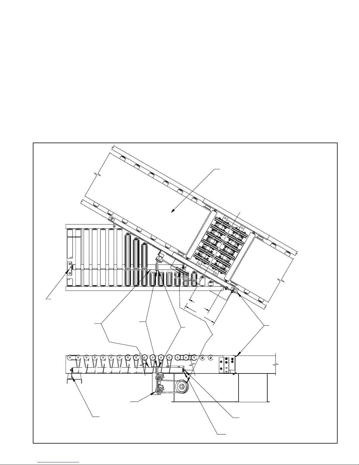
INSTALLING THE BELT
The conveyor drive belt has been pre-cut and the proper lacing attached at
the factory. Thread belt through conveyor per Figure 6B. Note that there
should be no air pressure on the pneumatic tensioner (if supplied). Pull belt
ends together and insert lacing pin. (Figure 6A). Adjust take-up to remove
slack from the belt.
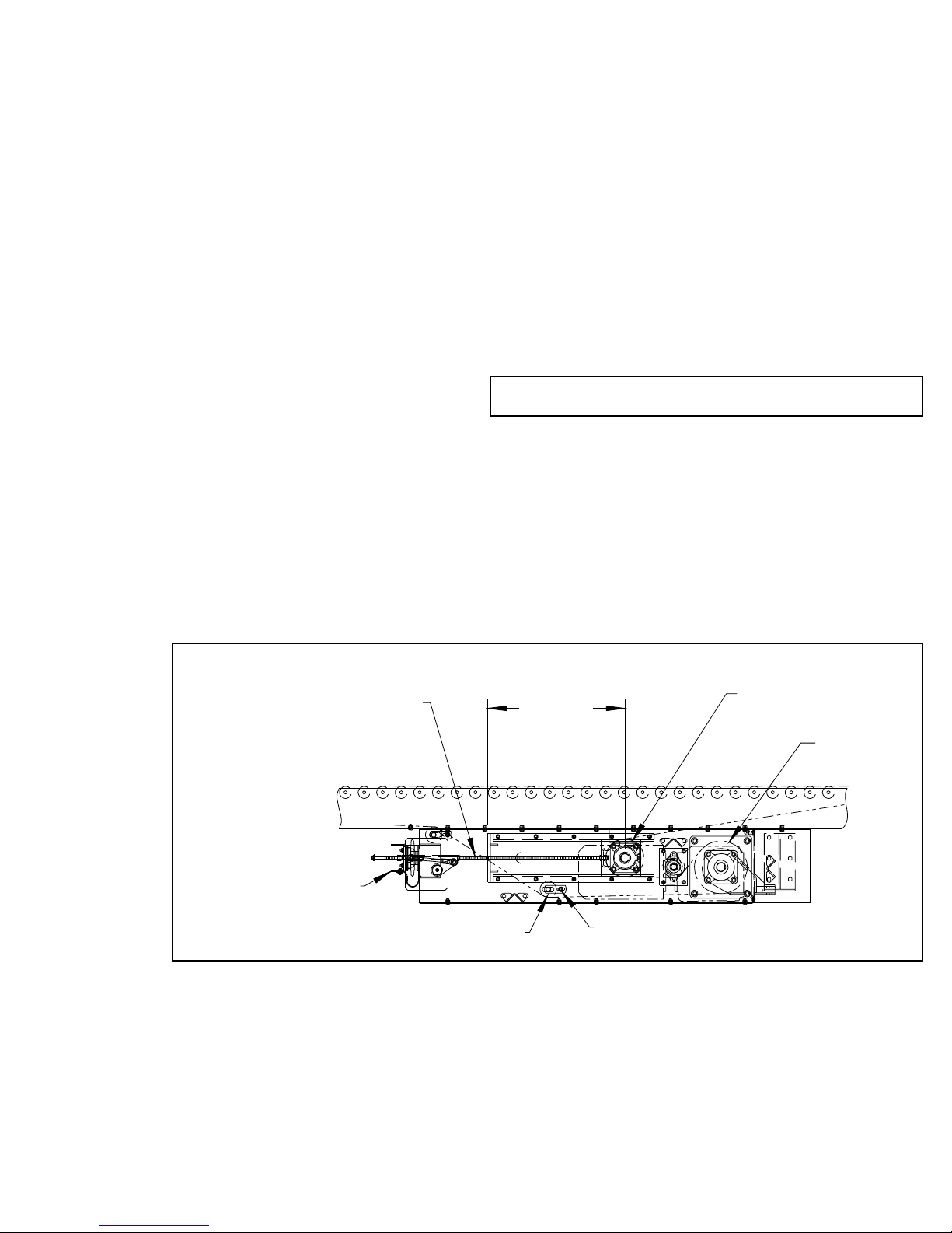
BELT TENSION
For maximum efficiency, maintain enough belt tension so drive pulley will
not slip when carrying the rated load. Belt tension should be adjusted with
the take-up pulley in the drive. (Figure 7) Keep pulley square with bed by
moving both take-up bolts an equal amount.
Pneumatic Tensioner (when supplied):
Initial Tension:
With no air pressure on tensioner, take up the belt until the unit runs and
the drive pulley does not slip (keeping pulley square). With unit turned
off, back the jam nuts off by a distance of 1/2”. Lock jam nuts at this loca-
tion. Starting at 10 psi, increase air pressure until the tensioner strokes
1/2” (measure gap between channel and UHMW block). Tensioner will now
have 2” of additional stroke and 1/2” of relief.
Resetting Tension:
When the tensioner approaches full stroke the take-up should be adjusted
until the tensioner is set at 1/2” again.
WARNING! Electrical controls shall be installed and wired by a qualified electrician.
Wiring information for the motor and controls are furnished by the equipment manu-
facturer.
CAUTION! Because of the many moving parts on the conveyor, all personnel in the
area of the conveyor need to be warned that the conveyor is about to be started.
Ambient Temperature
Degrees F SAE ISO
20-40 20 46 or 68
40-100 30 100
100-120 40 150
NOTE: If belt ends cannot be pulled together by hand, it may be necessary to loosen
take-up pulley (in drive) to minimum position or use a belt puller so lacing pin can be
easily inserted.
5

CAUTION! Excessive slippage will reduce
belt life and damage drive pulley lagging.
Never apply more tension than is needed.
Over-tension will cause extra wear to belt
and bearings and will require extra power
from drive.
TA IL ASSEMBLY
FLOW
DRIvE PULLEY
HIGH PERFORMANCE DRIvE
INTERMEDIATE DIvERTER
DIvERTER
INFEED END
DIvERTER
DISCHARGE END
RETURN BELT
RETURN BELT
RETURN BELT
TOP BELT
TOP BELT
TOP BELT
TA IL PULLEY
(POLEA DE RETORNO)
SNUB IDLER
(RODILLO DE
ALINEACION)
(BANDA SUPERIOR)
(BANDA DE RETORNO)
(BANDA DE RETORNO)
(BANDA DE RETORNO)
(BANDA SUPERIOR)
(BANDA SUPERIOR)
(DESVIADOR DEL EXTREMO
DE DESCARGA) (DESVIADOR DEL EXTREMO
DE ALIMENTACIÓN)
(MONTAJE DEL EXTREMO
DE RETORNO)
(UNIDAD MOTRIZ DE ALTO DESEMPEÑO)
(DESVIADOR INTERMEDIO)
TA IL PULLEY
(POLEA DE
RETORNO)
BELT
(BANDA)
TAKE UP PULLEY
(POLEA DE TENSION)
(POLEA MOTRIZ)
(FLUJO)
HEAv Y DUTY DRIvE
(UNIDAD MOTRIZ PARA TRABAJO PESADO)
PNEUMATIC TAKE UP
(WHEN SUPPLIED)
(TENSIONADOR NEUMÁTICO)
[CUANDO ES SUMINISTRADO]
SNUB IDLER
(RODILLO DE
ALINEACION)
FLOW
SUPPORT ANGLE
BELT
(BANDA)
(ANGULO DE SOPORTE)
(FLUJO)
SIDE “Y”
(LADO “Y”)
SIDE “X”
(LADO “X”)
B
D
BB
BA
C
BELT LACING
BELT
LACING PIN
(ENLACE DE BANDA)
(BANDA)
(PASADOR DE ENLACE)
FIGURE 6A
FIGURE 6B
FIGURE 6C
6

TRACKING THE BELT
The belt is tracked by one of two methods:
1. By manually adjusting drive pulley, tail pulley, return idlers, and snub
idlers.
2. By manually adjusting the diverter bank.
PRE-TRACKING INSPECTION
Before attempting to physically track the belt:
1. Make sure conveyor is level across the width and length of unit Adjust sup-
ports as necessary.
2. Check to make sure: drive pulley, tail pulley, snub idlers, and all return
idlers are square with conveyor bed. See illustrations 7 thru 8B. Dimension
“A” should be equal on both sides of unit.
3. Make sure belt has been properly threaded through conveyor. See “Belt
Installation’ page 6.
4. Check for improper loading. Feed should be in direction of belt travel,
centered on belt.
5. Make sure belt lacing has been installed correctly.
TRACKING BELT THROUGH DIVERTER BANK
(SEE FIGURE 6C)
Condition 1 (When belt is running in the direction (FLOW) With the arrow, but
belt drifts towards Side “Y”):
1. Remove center bolt and nut point (A).
2. Loosen bolts and nuts points (B).
3. Loosen jam nut point (C).
4. Tighten jam nut point (D) until belt tracks to desired location. (1/16” incre-
ments). (Let belt make at least one full revolution between 1/16” adjust-
ments.)
5. Tighten jam nut point (C).
6. Tighten bolts and nuts points (B).
Condition 2 (When belt is running in the direction (FLOW) with the arrow, but belt drifts
towards Side “X”):
1. Remove center bolt and nut point (A).
2. Loosen bolts and nuts points (B).
3. Loosen jam nut point (D).
4. Tighten jam nut point (C) until belt tracks to desired location.
5 Tighten jam nut point (D).
6. Tighten bolts and nuts points (B).
Note: When belt tracking adjustments are made,they should be minor (1/16
in. at a time.)
IMPORTANT: When belt tracking adjustments are made, they should be
minor (1/16 in. at a time on idlers, etc., should be sufficient.).
Give the belt adequate time to react to the adjustments. It may take several
complete revolutions around the conveyor for the belt to begin tracking prop-
erly on long, slow conveyor lines.
A) Stand at tail pulley looking toward drive and note what direction belt is
traveling.
B) Having observed belt and determined tracking problem, follow procedures
in “How to Steer The Belt”, See Figure 8C.
HOW TO STEER THE BELT
Condition 1. . .When the belt is running in the direction (FLOW) with the arrow,
but tracking (drifting) towards Side “X”, move the Snub Idler nearest the
INFEED end of Side “Y” towards the DISCHARGE end of the conveyor.
Condition 2. . . When the belt is running in the direction (FLOW) with the
arrow, but tracking (drifting) towards Side “Y”, move the Snub Idler nearest
the INFEED end of Side “X” towards the DISCHARGE end of the conveyor.
If Belt Direction (FLOW) is reversed, all the above conditions will remain the
same as in Figure 8C, except you are now viewing the conveyor from the
opposite end.
If belt continues to track improperly, re-check all items covered in “Pre-
Tracking Inspection” and make corrections as necessary.
TP SCREW TP PULLEY
DRIvE PULLE
Y
SNUB IDLER ADJUSTMENT BOLT
P
(POLEA TENSORA)
(ESCUADRANDO LAS POLEAS EN EL TENSOR MOTRIZ CENTRAL)
(TORNILLOS
TENSORES)
(POLEA MOTRIZ)
(RODILLO DE ALINEACION) (TORNILLO DE AJUSTE)
"A"
PNEUMATIC TAKE UP
(SUPPLIED WITH HIGH
PERFORMANCE DRIvE ONLY )
(TENSIONADOR NEUMÁTICO)
[SUMINISTRADO ÚNICAMENTE CON
LA UNIDAD MOTRIZ DE ALTO DESEMPEÑO)
NOTE: In all conditions, you are viewing the Conveyor Belt from the INFEED
end. All corrections will be made from the INFEED end of conveyor.
FIGURE 7
7

RETURN IDLER
(RODILLO DE RETORNO)
RETURN BELT
(BANDA DE RETORNO)
ADJUSTMENT BOLTS
(TORNILLO DE AJUSTE)
ADJUSTABLE IDLER BRACKET
(SOPORTE AJUSTABLE DEL RODILLO)
+ 1/16
- 0
1/8
"A"
(3 1/4" POLEA DE RETORNO)
[CARGA]
3 1/4" TAIL PULLEY (INFEED)
CLEARANCE
(ESPACIO LIBRE DE LA
GUARDA DE PUNTOS EXPUESTOS)
NIP POINT GUARD
6" TAIL PULLEY TP BOLT
(DISCHARGE)
(ESCUADRANDO LA POLEA
DE RETORNO DE 6")
[DESCARGA]
TAIL PULLEY
(TORNILLO TENSOR)
(6" POLEA DE RETORNO)
TAIL PULLEY
(POLEA DE
RETORNO)
SNUB IDLER
(RODILLO DE
ALINEACION)
FLOW
SIDE "X"
TAIL PULLEY
BELT SNUB IDLER
INFEED
DISCHARGE
TAIL PULLEY
SIDE "Y"
(RODILLO DE ALINEACION)
(POLEA DE RETORNO)(POLEA DE RETORNO)
(LADO"Y")
(BANDA)
(LADO"X")
(FLUJO)
(CARGA)
(DESCARGA)
FIGURE 8A
FIGURE 8B
FIGURE 8C
8

INFEED AND DISCHARGE PULLEYS AT DIVERTS
The pulleys have been designed to insure the product clears the belt. The
pulley shaft has one side milled out so the pulley can be installed in the high
position on the infeed end (see Fig. 9A, Detail A) and in a low position at the
discharge end (See Fig. 9A, Detail B). The discharge pulley will be place in
the frame with the milled portion of the shaft facing down this will lower the
pulley by approximately 1/8”.
ADJUSTING DIVERTER HEIGHT
The diverter will be adjusted to a height of 5/32 in. above the top of the belt.
This measurement should be taken where the belt is touching the bed not at
the pulley. Use a Straight edge placed on the belt at the infeed end of the
diverter; from bottom of straight edge to top of diverter wheel should measure
5/32 in. (see Fig. 9A, Detail D). If divert needs adjustment loosen 5/8-18 nut
atop adjustment Bolts; using screwdriver, adjust diverter to proper height.
Retighten 5/8-18 nuts atop adjustment bolts.
The pivoting diverter wheels have been aligned at the factory and should not
require initial adjustment. If it becomes necesary to align the diverter wheels,
the following procedure may be used.
1. Shut down the sorter.
2. Insure the diverter is in the straight through position. (See Figure 9B.)
3. Place a straight-edge against a diverter wheel support angle and check for
squareness with the conveyor frame.
4. Loosen the jam nut away from the rod end on the diverter cylinder rod.
5. Remove the bolt holding the rod end to the diverter pivot bar.
6. Adjust the rod end on the cylinder rod as needed to achieve proper align-
ment of the pivoting diverter wheels.
7. Tighten the jam nut, replace the rod end bolt, and re-check for square-
ness.
DETAIL A
SCALE 1:1
INFEED PULLEY
SET HIGH
PIvOT BAR ASSEMBLY
ADJUSTMENT BOLT
(POLEA DE ALIMENTA CIÓN
A NIVEL ALTO)
(TORNILLO HEXAGONAL 5/8-18 NC2B)
(TORNILLO DE AJUSTE) (ENSAMBLE DE LA BARRA PIVOTE)
(DETALLE “A”
ESCALA 1:1)
ADJUSTMENT BOLT
(TORNILLO DE AJUSTE)
ADJUSTMENT BLOCK
(BLOQUE DE AJUSTE)
DETAIL B
SCALE 1:1
(DETALLE “B”
ESCALA 1:1)
DISCHARGE PULLEY
SET LOW
(POLEA DE DESCARGA
A NIVEL BAJO)
DETAIL D
SCALE 1:1
(DETALLE “D”
ESCALA 1:1)
BDA
DIVERTER WHEEL
ROD END
JAM NUT
DIVERTER CYLINDER
PIVOT BAR
DIVERTER
ROD END BOLT
SUPPORT ANGLE
DIVERTER WHEEL
(ANGULO DEL SOPORTE DE LA
RUEDA DEL CLASIFICADOR)
(BARRA ACTUADORA)
(CONTRA TUERCA)
(EXTREMO DE BARRA)
(TORNILLO DEL
EXTREMO DE BARRA)
(BARRA DEL EJE
DEL DESVIADOR)
(RUEDA DEL DESVIADOR)
FIGURE 9A
FIGURE 9B
9

The ProSort SC1 and ProSort SC2 sorters may be supplied with or without
special slaved powered spurs at the diverters. This section explains how to
properly place any spur and how to properly install the spur drive o-ring on
slaved powered spurs.
SPUR PLACEMENT
1. Mount the spur to the side frame of the sorter using the supplied brackets at
the location shown in Figure 10. It may be necessary to drill a hole in the top
flange of the conveyor frame to accept the spur bracket mounting bolt.
2. Check to make sure that the spur is mounted at the proper height. (Proper
height is determined by laying a straight edge on sorter belt, spur rollers or
1st roll of skatewheels should be level with sorter belt). This should be done
to insure the proper diverting of packages. If the spur is a gravity spur, make
sure that the spur is set at a sufficient pitch to properly convey packages
from the sorter.
1. Route the drive o-ring as shown in figure 10. Make sure that the o-ring lies
in the groove of the plastic collar on the spur drive roller and is properly routed
through the idler sheaves as shown.
2. Using a smooth, stiff object, such as a large straight wrench, stretch the
o-ring over and onto the spur drive sheave of the diverter.
3. Visually inspect the o-ring routing. If the spur drive sheave appears to be
out of alignment with the idler sheaves, adjust it by loosening the set screws
in the sheave and sliding the sheave on the shaft until alignment is achieved.
Re-tighten the set screws.
4. Run the sorter and observe the spur for proper operation.
If it becomes necessary to replace a roller o-ring or a spur drive o-ring, the
following procedure should be used.
1. Pop the spur drive roller out of the mounting brackets by depressing the
spring-loaded hex shaft of the roller.
2. Slide the new o-ring over the spur drive roller, working it into position
through the existing o-rings.
3. Re-install the spur drive roller in the brackets, taking care to install the roller
shaft in the lower hole of the spur plate bracket and the inside hole in the
discharge end bracket, as shown.
12"
8 3/16"
END BRACKET
DISCHARGE
SPUR PLATE BRACKET
INSIDE HOLE OF BRACKET
INSTALL ROLLER SHAFT IN
LOWER HOLE OF BRACKET
INSTALL ROLLER SHAFT IN
IDLER SHEAvE
SHEAvE
SPUR DRIvE
COLLAR
PLASTIC
ROLLER
SPUR DRIvE SPUR MOUNTING BRACKET
C
(PLACA DE MONTAJE DE LA ESPUELA)
(POLEA IMPULSADORA
DE LA ESPUELA)
(GUÍA DEL
ANILLO-O)
(INSTALE EL EJE DEL RODILLO EN EL
ORIFICIO SUPERIOR DEL SOPORTE)
(RODILLO IMPULSADOR
DE LA ESPUELA)
(POLEA ACANALADA PARA RETORNO)
(SOPORTE DEL EXTREMO DE DESCARGA)
(INSTALE EL EJE DEL RODILLO EN EL
ORIFICIO INFERIOR DEL SOPORTE)
(PLACA SOPORTE DE LA ESPUELA)
(COLLAR
PLASTICO)
L
SORTER BELT
(BANDA DEL CLASIFICADOR)
FIGURE 10
10

TROUBLE SHOOTING DRIVES
TROUBLE CAUSE SOLUTION
Conveyor will not start or
motor quits frequently.
1) Motor is overloaded.
2) Motor is drawing too much current.
1) Check for overloading of conveyor.
2) Check heater or circuit breaker and change if necessary
Drive belt wears exces-
sively.
1) Belt is too loose. 1) Tighten belt.
2) Check pneumatic tensioner. (see below)
Loud popping or grind-
ing noise.
1) Defective bearing. 1) Replace bearing.
Motor or reducer over-
heating.
1) Conveyor is overloaded.
2) Low voltage to motor.
3) Low lubricant level in reducer.
1) Check capacity of conveyor and reduce load to recommended level.
2) Have electrician check and correct as necessary.
3) Relubricate per manufacturer’s recommendations.
Belt does not move, but
drive runs.
1) Conveyor is overloaded.
2) Belt is too loose.
3) Lagging on drive pulley is worn
1) Check capacity of conveyor and reduce load to recommended level.
2) Tighten belt.
3) Check pneumatic tensioner. (see below)
4) Replace drive pulley and tighten belt.
Diverter wheels not turn-
ing under loaded condi-
tions.
1) Conveyor is overloaded.
2) Package flow obstructed by guard rail or other
object.
1) Check capacity of conveyor and reduce load to recommended level.
2) Clear obstruction.
Inoperative diverter. 1) No air pressure to cylinder.
2) Air solenoid defective.
1) Check for restricted or broken air line.
2) Replace air solenoid.
Inoperative pneumatic
tensioner.
1) No air pressure to air bag.
2) Tensioner at full stroke.
1) Check for restricted or broken air line.
2) Resent tensioner. (see belt tension)
Product not diverting. 1) Divert height out of adjustment.
2) Out of spec product.
1) Adjust divert to proper height.
2) Remove or put product in tote.
Product bounces at
diverts.
1) Divert height out of adjustment.
2) Out of spec product.
1) Adjust divert to proper height.
2) Remove or put product in tote.
TROUBLE SHOOTING DRIVE BELT TRACKING
TROUBLE CAUSE SOLUTION
Belt creeps to one side
at tail pulley.
1) Return idler, or snub idler near tail pulley not prop-
erly aligned or square with bed.
1) Adjust as necessary. See “Belt Tracking” in this manual for details.
Entire belt creeps to one
side.
1) Conveyor not straight.
2) Conveyor not level.
3) Material build-up on rollers, pulleys, or idlers.
1) Re-align bed sections as necessary.
2) Correct as necessary.
3) Remove residue and install belt cleaners or scrapers if possible.
11

Dibujo de Partes del Modelo ProSort SC
22
21
10 15
16
17
9867
13
14
24
26
25
11
20
1
SEE PAGE 17 FOR PNEUMATIC
TENSIONER (SUPPLIED ON HIGH
PERFORMANCE DRIvE ONLY)
(VEA LA PAGINA 17 PARA EL
TENSIONADOR NEUMATICO)
[PROVEIDO SOLAMENTE CON
LA UNIDAD MOTRIZ DE ALTO
DESEMPEÑO]
SEE PAGE 16 FOR HIGH PERFORMANCE SHAFT
MOUNTED CENTER DRIvE AND
PAGE 18 FOR HEAvY DUTY SHAFT MOUNTED CENTER DRIvE
(VEA LA PAGINA 16 PARA EL EJE DE ALTO DESEMPEÑO MONTADO
EN UNIDAD MOTRIZ CENTRAL Y LA PAGINA 18 PARA EL EJE DE
TRABAJO PESADO MONTADO EN UNIDAD MOTRIZ CENTRAL.)
"A"
"A"
(SECCION "A-A")
SEE PAGE 19 FOR TAILS
(VEA LA PAGINA 19 PARA
LOS EXTREMOS DE
RETORNO)
2
OAW
BR
1 1/2"
6 1/2"
10 1/4"
12

Dibujo de Partes del Modelo ProSort SC
21 22
4
15
16
17
10 38697
24
25
13
12
11
SEE PAGE 20 & 21
FOR DIVERTERS
(VEA LA PAGINA 20 & 21
PARA DESVIADORES)
19
26
SEE PAGE 24 & 25 FOR SPURS
(VEA LA PAGINA 24 & 25 PARA ESPUELAS)
8 3/16"
12"
24" MIN
30°
14
13

2
2
21
22
SEE PAGE 24 & 25 FOR SPURS
(VEA LA PAGINA 24 & 25 PARA ESPUELAS)
SEE PAGE 19 FOR TAILS
(VEA LA PAGINA 19
PARA EXTREMOS DE RETORNO)
4
10
9
8
7
3
15
16
17
65
13
14
24
26
25
11
18
SEE PAGE 20 & 21 FOR DIVERTERS
(VEA LA PAGINA 20 & 21 PARA DESVIADORES)
"B"
"B"
SECTION "B-B"
(SECCION "B-B")
OAW
BR
1 1/2"
6 1/2"
10 1/4"
12
10
23
Dibujo de Partes del Modelo ProSort SC
14

Lista de Partes del Modelo ProSort SC
Ref No Part No Description
1
2
-
-
-
-
Drive
High Performance Shaft Mounted Drive with
Pneumatic Tensioner (See page 16 & 17)
Heavy Duty Shaft Mounted Drive (See page 18)
6” Tail Assembly (See page 19)
3
4
5
6
-
-
-
-
-
PT-132837-048
Diverter Assembly (See page 20 & 21)
Spur Assembly (See page 24 & 25)
3 1/4” Dia Tail Assembly (See page 19)
Bed Channel
4’ Long
-
-
-
-
-
PT-132837-060
PT-132837-072
PT-132837-084
PT-132837-090
PT-132837-096
5’ Long
6’ Long
7’ Long
7’6” Long
8’ Long
-
-
7
8
9
PT-132837-108
PT-132837-120
B-23316
B-03916
B-05477
9’ Long
10’ Long
Splice Plate
Bed Spacer (Specify BR)
Threaded Section Spacer (Specify BR)
10
11
12
-
-
B-01982
B-15299
-
SA-015669-116
SA-015669-164
1.9 Dia. Galvanized Roller (Specify BR)
2 1/2” Dia Snub/Idler Roller (Specify BR)
2 1/8” Dia. Roller Assembly
14 1/2” BR
20 1/2” BR
-
-
13
14
15
SA-015669-212
SA-015669-260
PT-016128
PT-013975
-
26 1/2” BR
32 1/2” BR
Support Channel
Bed Spacer (Specify BR)
Belt-Black Ultimate 140 BBS
-
-
-
-
065.5031
065.5061
065.5081
065.5091
15” BR
21” BR
27” BR
33” BR
16
17
18
19
-
-
-
-
PT-017045
PT-020332
PT-020333
PT-020334
# 2SPG Clipper Lacing (Specify Length)
# 13 Duralink Lacing Pin (Specify Length)
Snub Roller Guard (at Divert Infeed) (Specify BR)
Snub Roller Guard (at Divert-2 3/4 x 4 x 3/8) (Specify BR)
Snub Roller Guard (at Divert-2 3/4 x 4 x 1) (Specify BR)
Snub Roller Guard (at Divert-2 3/4 x 3 1/4 x 3/8) (Specify BR)
20
21
22
23
24
-
PT-020335
PT-017017-L
PT-017017-R
B-00944
-
B-00913
Snub Roller Guard (at Drive) (Specify BR)
Snub Guard Mounting Bracket (LH)
Snub Guard Mounting Bracket (RH)
7/16” Hex Idler Bracket
MS Type Pivot Plate
3 11/16” High
-
25
-
-
-
B-02112
-
B-00914
B-12777
B-12778
1 9/16” High
Floor Support Frame
6” High (Specify OAW)
7” High (Specify OAW)
8” High (Specify OAW)
-
-
-
-
-
B-00915
B-00916
B-00917
B-02098
B-00919
9” High (Specify OAW)
11 1/2” High (Specify OAW)
14 1/2” High (Specify OAW)
18 1/2” High (Specify OAW)
22 1/2” High (Specify OAW)
-
-
-
-
-
-
26
B-00921
B-00923
B-00925
B-02107
B-02109
B-02111
B-00911
32 1/2” High (Specify OAW)
44 1/2” High (Specify OAW)
56 1/2” High (Specify OAW)
68 1/2” High (Specify OAW)
78 1/2” High (Specify OAW)
90 1/2” High (Specify OAW)
Adjustable Foot Assembly (Specify Length)
15

OAW
BR 1 1/2"
9
2
21
1
12
8
625
27
510 11 13
3
4
14
19
20
26
22
17 15
16
18
23
7
24
Ref No Part No Description
1
2
-
-
3
Per Order
-
SA-006747
SA-012345
PT-016164-L
Gearmotor (Shaft Mounted)
8” Dia. Drive Pulley (Fully Lagged) (Specify OAW)
KA57 Gearmotor (3 and 5 hp)
KA67 Gearmotor (7 1/2 and 10 hp)
Drive Plate Assembly (LH)
4
5
6
7
-
-
8
PT-016164-R
B-23616
910.0018
-
WA-009783
WA-007993
-
Drive Plate Assembly (RH)
Pulley Plate
4-Bolt Flange Bearing-1 11/16” Bore
Mounting Angle Weldment
KA57 Gearmotor
KA67 Gearmotor
Torque Arm Weldment
-
-
9
10
11
WA-005018-L
WA-005018-R
WA-005063
PT-016285
010.00222
Left Hand Drive
Right Hand Drive
3 3/4” Dia. Snub Idler (Specify OAW)
Snub Idler Plate
2-Bolt Flange Bearing-1” Bore
12
13
14
15
16
B-24801
B-20935
B-18682
B-18686
B-18669
6” Dia Tail Pulley (Specify OAW)
Take-up Plate Assembly
Take-up Plate Weldment
HD Guide
Bearing Guide
17
18
19
20
21
910.0017
G-02425
B-04842
B-03916
B-08336
4-Bolt Flange Bearing-1 7/16” Bore
2 5/8” Dia Roller Assembly (Specify BR)
11/16” Hex Idler Bracket
Bed Spacer (Specify BR)
Rear Guard (Specify OAW)
22
23
24
25
26
B-18687
B-18688
B-18689
B-08339
B-03092-352
Bottom Guard (Infeed) (Specify OAW)
Bottom Guard (DIscharge) (Specify OAW)
Front Guard (Specify OAW)
Formed Clip
Take-up Screw-1/2-13 x 22” Lg
27 049.310 1/4-20 U-Type Speed Nut
Dibujo y Lista de Partes del Eje Montado de la Unidad Motriz de Alto Desempeño
16

7
1
19
11
12
2
22
5
8
93
18
20
22
16
15
25
17
4
14
6
10
23
OAW
BR
24
13
21
26
27
Dibujo y Lista de Partes del Tensionador Neumático
Ref No Part No Description
1
2
3
4
5
SA-009467
SA-009486
WA-006634
WA-006650
B-11302
Cam Roller Assembly (Specify OAW)
Linkage Assembly
Take-up Tube
Air Bag Support Weldment (Specify OAW)
Mounting Angle
6
7
8
9
10
PT-021883
PT-021884
PT-021885
PT-03092-576
PT-022040
Take-up Pull Channel (Specify OAW)
Front Guard (Specify OAW)
Guide Block
1/2-13 Take-up Bolt
Linkage Rod Attachment Angle
11
12
13
-
-
PT-022989-R
PT-022989-L
-
067.01079
067.02080
Side Guard RH
Side Guard LH
Air Bag Guard
18” OAW
20” OAW
-
-
-
-
-
067.02081
067.02082
067.02083
067.02084
067.02085
22” OAW
24” OAW
26” OAW
28” OAW
30” OAW
-
-
-
-
-
067.02086
067.02087
067.02088
067.02089
067.02090
34” OAW
36” OAW
40” OAW
42” OAW
46” OAW
-
-
-
14
15
067.02091
067.02092
067.02093
094.1072
094.1941
48” OAW
52” OAW
54” OAW
Air Bag
Filter Regulator (20 psi MAX)
16
17
18
19
20
094.197
094.14099
094.1408
094.1149
092.078
Shutoff Valve
Brass Reducer-Female to Male 1/4” NPTF
Plastic Elbow-Male 3/8” PLST-1/4” NPTF
3/8” OD Polyurethane Tubing
3/8” To 3/8” Brass Male Nipple
21
22
23
24
25
092.0081
049.5045
040.315
041.798
099.527
3/8” NPT 90 Brass Pipe Elbow
7/16-14 X 1 1/4” Lg. Hardened Hex Bolt
3/8-16 X 6” Hex Bolt
3/8-16 Nylon Locknut
Felt Washer
26
27
PT-047407
032.2116
Prox Bracket
Proximity Switch
17

Dibujo y Lista de Partes del Eje Montado para Trabajo Pesado
29
18 15
1
8
51"
7
14
23
4
12
3
13
6
24
22
17
21
11 19
10
16
520
12"
1 1/2 "
OAW
BR
Ref No Part No Description
1
2
3
4
5
Per Order
SA-010074
PT-023078-L
PT-023078-R
B-23616
Gearmotor (Shaft Mounted)
8” Dia. Drive Pulley (Fully Lagged) (Specify OAW)
Drive Plate Assembly (LH)
Drive Plate Assembly (RH)
Pulley Plate
6
7
8
-
-
910.0018
WA-007993
-
WA-006751-L
WA-006751-R
4-Bolt Flange Bearing-1 11/16” Bore
Mounting Plate Weldment
Torque Arm Weldment
Left Hand Drive
Right Hand Drive
9
10
11
12
13
B-24801
B-20935
WA-006741
PT-023134
PT-023133
6” Dia Tail Pulley (Specify OAW)
Take-up Plate Assembly
Take-up Plate Weldment
HD Guide
Bearing Guide
14
15
16
17
18
910.0017
G-02425
B-04842
B-03916
B-08336
4-Bolt Flange Bearing-1 7/16” Bore
2 5/8” Dia Roller Assembly (Specify BR)
11/16” Hex Idler Bracket
Bed Spacer (Specify BR)
Rear Guard (Specify OAW)
19
20
21
22
23
PT-023100
PT-024326
B-18689
B-08339
B-03092-200
Bottom Guard (Infeed) (Specify OAW)
Bottom Guard (DIscharge) (Specify OAW)
Front Guard (Specify OAW)
Formed Clip
Take-up Screw-1/2-13 x 12 1/2” Lg
24 049.310 1/4-20 U-Type Speed Nut
18

34
212
13 16 17 11
10
6
1
7
8
59
14
15
6" DISCHARGE TAIL
(EXTREMO DE DESCARGA DE 6")
3 1/4" INFEED TAIL
(EXTREMO DE CARGA DE 3 1/4")
18
19
21
20
Dibujo y Lista de Partes del Eje Montaje del Extremo de Retorno
Ref No Part No Description
-
1
2
3
4
-
WA-008284
WA-011933
WA-011934
B-21155
6” System End (Discharge)
6” Dia. Tail Pulley Assembly (Specify BR)
RH Channel Assembly
LH Channel Assembly
Slider Plate Assembly (Specify OAW)
5
6
7
8
9
PT-042063
B-14743
B-20445
090.262
010.10372
Bearing Spacer - 1 7/16” Bore
1.9” Dia. Galv. Roller (Specify BR)
1.9” Dia Galv Pop-out Roller (Specify BR)
Pop-out Roller Bracket
3-Bolt Flange Bearing - 1 7/16” Bore
10
-
11
12
13
093.215
-
SA-000676
PT-006399
B-23316
Roller Bracket
3 1/4” System End (Infeed)
3 1/4” Dia. Tail Pulley Assembly (Specify BR)
Channel
Splice Plate
14
15
16
17
18
B-03191
B-23060
PT-006398
B-25643
SA-035140
Butt Coupling
Slider Pan (Specify BR)
Pulley Mount
Nip Point Guard (Specify BR)
2-1/2” Dia. Snub/Idler Roller (Specify BR)
19
20
21
B-13708
B-13707
B-14734-H
Snub Guard (Specify BR)
Snub Guard Mounting Bracket
11/16” Hex Idler Bracket
19

Dibujo de Partes del Desviador
FLOW
(FLUJO)
FLOW
(FLUJO)
FLOW
(FLUJO) FLOW
(FLUJO)
FLOW
(FLUJO) FLOW
(FLUJO)
FLOW
(FLUJO)
DOUBLE SIDED WITH SLAvES
(DE LADO DOBLE CON ESCLAVADO)
DOUBLE SIDED W/O SLAvES
(DE LADO DOBLE SIN ESCLAVADO)
SINGLE SIDED WITH SLAvE
(DE LADO SENCILLO CON ESCLAVADO)
DISCHARGE END DIvERTER
(DESVIADOR EN EXTREMO DE DESCARGA)
INFEED END DIvERTER
(DESVIADOR EN EXTREMO DE CARGA)
INTERMEDIATE DIvERTER
(DESVIADOR INTERMEDIO)
SINGLE SIDED W/O SLAvE
(DE LADO SENCILLO SIN ESCLAVADO)
20
This manual suits for next models
1
Table of contents
Languages:
Other HYTROL Accessories manuals