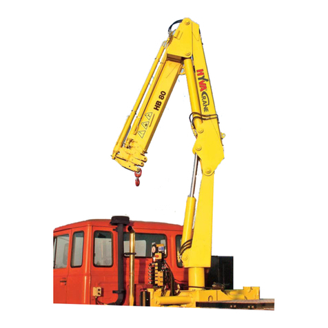
HYVA Crane HB Series User manual

COD H624149_02-00
Żuraw
Truck crane
Autolaadkraan
SERIA: TYP:
SERIES: HB MODEL:
SERIE: TYPE:
HB50
WAŻNE WG NUMERU SERYJNEGO
VALID FROM SERIAL NO.
GELDIG VANAF SERIENR.
200000
INSTRUKCJA OBSŁUGI, UTRZYMANIA, LISTA OSTRZEŻEŃ
•
WARNINGS - OPERATION AND MAINTENANCE MANUAL
•
HANDLEIDING VOOR WAARSCHUWINGEN, GEBRUIK EN
ONDERHOUD
ATTENTION! Lire attentivement ce manuel avant l’utilisation
CAUTION! Read this manual carefully prior to use
UWAGA! Przeczytaj uważnie instrukcje przed użyciem
CAUTION! Read this manual carefully prior to use
WAARSCHUWING!½Lees deze handleiding aandachtig door, voordat u met de kraan gaat werken

1
PREF1/HYVA.02-00
P 1/1
Prawa autorskie: Hyva International
B.V.
Publikacja: 07/2007
Adres producenta:
Hyva International B.V.
Ondernemingsweg 1
2404 HM Alphen aan den Rijn
The Netherlands
E-mail: info@hyva.com
www.hyva.com
Zabronione jest odtwarzanie,
umieszczanie w mediach lub
modyfikowanie treści
instrukcji lub jakichkolwiek
części niniejszego
podręcznika.
INFORMACJA:
Następujące części lub
urządzenia są standardowo
zamontowane tylko na żurawiu i
sprzedawane na rynkach Unii
Europejskiej.
Przyciski bezpieczeństwa i zawory.
Ogranicznik udźwigu.
Copyright: Hyva International B.V.
Published: 07/2007
Address of Manufacturer:
Hyva International B.V.
Ondernemingsweg 1
2404 HM Alphen aan den Rijn
The Netherlands
E-mail: info@hyva.com
www.hyva.com
It is forbidden to reproduce, store on
electronic media or modify the
contents of this manual or any
parts thereof.
NOTE:
The following parts or de-
vices are fitted standard
only on cranes sold within the
market of the European Union.
Emergency buttons and associated
solenoid valve
Rated capacity limiter.
Copyright: Hyva International B.V.
Publicatie: 07/2007
Adres van de Fabrikant:
Hyva International B.V.
Ondernemingsweg 1
2404 HM Alphen aan den Rijn
The Netherlands
E-mail: info@hyva.com
www.hyva.com
Het is verboden de inhoud van deze
handleiding of delen daarvan op
enigerlei wijze te vermenigvuldi-
gen, electronisch op te slaan of te
wijzigen.
NOTE:
De volgende onderdelen
of voorzieningen zijn al-
leen standaard gemonteerd op
kranen die binnen de Europese
Unie op de markt gebracht wor-
den.
Noodstopknoppen en bijbehorend
electro-magnetisch ventiel.
Lastmomentbegrenzer.

2
PREF2HYVA.02-00
P 1/1
Adres firmy montażowej
Data odebrania maszyny
Firma montażowa musi podać swój
adres i przybić pieczątkę w tym
miejscu.
OSTRZEŻENIE:
Jako użytkownik końcowy
jesteś
upoważniony do otrzymania
kopii instrukcji wydanych przez
Hyva International B.V.
zawierających informacje o
żurawiu.
Adresy
Addresses
Adressen
Installer’s address
Machine collection date
The installer must put his address and
stamp in this space.
WARNING:
As the end user, you are
entitled to ask the installer
for a copyof the assembly
manual containing the instructions
issued by Hyva International B.V.
for the installation of your crane.
Adres van de Opbouw -
leverancier
Afleverdatum van de
machine
De opbouwleverancier moet hier zijn
adres en stempel plaatsen.
LET OP:
Als eindgebruiker bent u
gerechtigd de opbouw-
leverancier om een copie van de
montage -instructies van Hyva
International B.V. te vragen.

Podręcznik ten składa się z 7
rozdziałów.
Strony poszczególnych rozdziałów
są identyfikowane odpowiednim
symbolem.
Użyte symbole opisane zostały
poniżej.
Rozdział A (Informacje Ogólne)
Rozdział ten zawiera ważne
informacje ogólne przeznaczone do
zapoznania Cię z maszyną, jak
również dane dotyczące identyfikacji
żurawia.
Specyfikuje umiejętności,
wymagania oraz inne cechy jakie
musi posiadać operator.
Rozdział B (Wymagania i
Specyfikacja)
Rozdział ten zawiera wszystkie
techniki charakterystyczne żurawia
w jego standardowym ustawieniu.
Rozdział C (Urządzenia i zasady
bezpieczeństwa
)
Rozdział ten przedstawia
wszystkie zasady, instrukcje
oraz informacje dotyczące
bezpieczeństwa operatorów i
urządzenia.
Spis rozdziałów
List of sections
Lijst van de Delen
This manual comprises 7 sections.
The pages of each section are iden-
tified by a symbol.
The symbols used are described
below.
Section A (General Information)
This section contains important gen-
eral information intended to ac-
quaint you with the machine, as
well as data for the exact identifi-
cation of the crane.
Specifies the skills, requirements
and other attributes that the op-
erator must posses.
Section B (Performance Data and
Specifications)
This section contains all the techni-
cal characteristics of the crane in
its standard set-up.
Section C (Safety Rules and De-
vices)
This section sets forth all the rules,
instructions and information re-
garding both operator and ma-
chine safety.
3
PREF3/718.02-00
P 1/2
Deze handleiding is onderverdeeld
in 7 hoofdstukken.
Op de bladzijden van ieder hoofd-
stuk staat een kenmerk.
De gebruikte symbolen worden
hieronder omschreven.
Deel A (Algemene Informatie)
Dit deel bevat belangrijke algeme-
ne informatie, bedoeld om u be-
kend te maken met de machine,
alsook met de exacte identificatie
gegevens van de kraan.
Dit deel specificeert de vaardighe-
den, eisen en attributen waaraan
de bedieningsman moet voldoen
en/of die hij moet bezitten.
Deel B (Prestaties en Specificaties)
Dit deel bevat alle technische spe-
cificaties van de kraan in stan-
daard uitvoering.
Deel C (Veiligheidsvoorschriften en
-voorzieningen)
Dit deel bevat opeenvolgend alle
regels, instructies en informatie
met betrekking tot de veiligheid
van de bedieningsman en zijn
machine.

3
PREF3/718.02-00
P 2/2
Rozdział E
(Opis sterowania i
narzędzi)
Rozdział ten wyjaśnia oraz ilustruje
różne sterowania i narzędzia
umieszczone na urządzeniu.
Rozdział F (Instrukcje sterowania)
Rozdział ten przedstawia oraz
ilustruje różne ruchy urządzenia.
Rozdział G (Utrzymanie)
Rozdział ten zawiera wykresy oraz
tabele informujące o pracach
serwisowych żurawia oraz o ich
harmonogramach.
Rozdział H (Serwisowe formularze
sprawdzające)
Zawiera formularze serwisowe i
konserwatorskie, które muszą być
wypełniane, oraz przykłady
szczegółów, które powinny być
zamieszczane.
Spis rozdziałów
List of sections
Lijst van de Delen
Section E (Description of Controls
and Instruments)
This section explains and illustrates
the various controls and instru-
ments located on the machine.
Section F (Operating Instructions)
This section describes and illus-
trates the various machine move-
ments.
Section G (Maintenance)
This section contains charts and ta-
bles covering crane maintenance
jobs and schedules.
Section H (Service Forms - Check
Sheet)
The appendix includes the mainte-
nance and servicing forms that
must be filled in and an example
of the details that should be re-
corded.
Deel E (Beschrijving van de Bedie-
ningselementen en Instrumenten)
Dit deel omschrijft en illustreert de
verschillende bedieningselemen-
ten en instrumenten die op de
machine aanwezig zijn.
Deel F (Bedieningsinstructies)
(Bedienungsanleitung)
Dit deel omschrijft en illustreert de
verschillende machinebewegin-
gen.
Deel G (Onderhoud)
Dit deel bevat diagrammen en ta-
bellen betreffende het onderhoud
en onderhoudsintervallen.
Deel H (Onderhoudsaantekenin-
gen)
De bijlage bevat de onderhouds- en
controlebladen die ingevuld die-
nen te worden; met daarbij een
voorbeeld.

Spis treści
Table of contents
Inhoudsopgave
4
PREF4/545.02-00
P 1/3
00.1 Wydanie - Ogólne
00.2 Adresy
00.3 Spis rozdziałów
00.4 Spis treści
A.00 ROZDZIAŁ A
(INFORMACJE
OGÓLNE
)
A.01 Objaśnienia użytych
terminów
A.02 Symbole
A.03 Identyfikacja żurawia
A.04 Lokalizacja ostrzeżeń na
żurawiu
A.05 Objaśnienia głównych
elementów
A.06 Informacje dla
użytkownika
A.07 Obowiązki i
odpowiedzialność
A.08 Istotne wymagania
A.09 Miejsce sterowania
B.00 ROZDZIAŁ B
(WYKONANIE I
SPECYFIKACJA
ŻURAWIA Z HAKIEM)
B.01 Zast. dozwolone
B.02 Charakterystyka
techniczna
B.03 Wymiary gabarytowe
B.04 Wykres pracy żurawia
B.05 Schemat hydrauliczny
B.06 Schemat elektryczny
C.00 ROZDZIAŁ C
(URZĄDZENIA I ZASADY
BEZPIECZEŃSTWA)
C.01 Główne zasady
bezpieczeństwa
C.02 Urządzenia bezp.
C.03 Pozostałe
niebezpieczeństwa i
obszary niebezpieczne
00.1 Edition- General notes
00.2 Addresses
00.3 List of sections
00.4 Table of contents
A.00 SECTION A
(GENERAL INFORMA-
TION)
A.01
Explanation of terms
used
A.02 Symbols
A.03 Crane identification
A.04
Notices located on the
crane
A.05 Description of main com-
ponent parts
A.06 Information for the user
A.07 Duties and
responsabilities
A.08 Essential requirement
A.09 Control station
B.00 SECTION B1
(PERFORMANCE
DATA AND SPECIFI-
CATIONS CRANE
WITH HOOK )
B.01
Permitted use
B.02
Technical characteristics
B.03
Overall dimensions
B.04
Crane working diagram
B.05
Hydraulic diagram
B.06
Wiring diagram
C.00 SECTION C
(SAFETY RULES
AND DEVICES)
C.01 General safety rules
C.02
Safety devices
C.03
Residual risks and risk
areas
00.1 Publicatie - Diversen
00.2 Adressen
00.3 Lijst van de Delen
00.4 Inhoudsopgave
A.00 DEEL A
(ALGEMENE INFOR -
MATIE)
A.01 Uitleg van de gebruikte
termen
A.02 Symbolen
A.03 Kraanidentificatie
A.04
Aanwijzingen op de
kraan
A.05
Beschrijving van de
hoofd-onderdelen
A.06
Informatie voor de ge-
bruiker
A.07 Plichten en verantwoor-
delijkheden
A.08 Fundamentele eisen
A.09 Bedienplaatsen
B.00 DEEL B
(PRESTATIES EN
TECHNISCHE GEGE-
VENS VAN DE KRAAN
MET HAAK )
B.01 Toegestane gebruik
B.02 Technische kenmerken
B.03 Totaalafmetingen
B.04 Werkdiagram
B.05 Hydraulisch schema
B.06 Bedradingsschema
C.00 DEEL C
(VEILIGHEIDSVOOR-
SCHRIFTEN EN -
VOORZIENINGEN)
C.01 Algemene veiligheidsei-
sen
C.02 Veiligheidsvoorziening
C.03 Resterende risicňs en ri-
sico-gebieden

4
PREF4/545.02-00
P 2/3
E.00 ROZDZIAŁ E E.00
(STEROWANIE I
NARZĘDZIA)
E.01 Lampki wskazujące na E.01
panelu żurawia
E.02
Wskaźnik poziomu
E.02
oleju
E.03 Sterowanie żurawia E.03
F.00 ROZDZIAŁ F F.00
(INSTRUKJCE STEROWANIA)
F.01 Wprowadzenie F.01
F.02 Uruchomienie F.02
F.03 Stabilizacja żurawia
F.03
F.04 Rozkładanie/składanie
F.04
żurawia
F.05 Używanie mechanicznego
F.05
wysięgu
F.06 Sprawdzenie żurawia
F.06
F.07 Problemy
F.07
F.08
Zadziałanie zaworu
F.08
YVH1
F.09 Wyłączenie/wykluczenie
F.09
ogranicznika udźwigu
G.00 ROZDZIAŁ G G.00
(UTRZYMANIE)
G.01 Wprowadzenie
G.01
G.02 Plan przeglądów
G.02
G.03 Smarowanie
G.03
G.04 Sprawdzanie poziomu G.04
oleju w zbiorniku
G.05 Wymiana oleju G.05
w zbiorniku
G.06 Wymiana filtra oleju G.06
W zbiorniku
G.07 Sprawdzenie zużycia płytek- G.07
ślizgowych
G.08 Sprawdzanie dokręcenia G.08
śrub
G.09 Charakterystyki olejów i G.09
smarów
G.10 Demontaż G.10
Spis treści
Table of contents
Inhoudsopgave
SECTION E E.00
(CONTROLS
AND INSTRUMENTS )
Indicator lights on crane E.01
pannels
Reservoir gauges E.02
Crane operation controls E.03
SECTION F F.00
(OPERATING
INSTRUCTIONS)
Introduction F.01
Start-up operations F.02
Stabilising the crane F.03
Opening /closing the
F.04
crane
Using the manual exten- F.05
sions
Crane check-up F.06
Troubleshooting F.07
Release of solenoid
F.08
valve YVH1
Exclusion of rated capac- F.09
ity limiter
SECTION G G.00
(MAINTENANCE )
Introduction G.01
Maintenance schedule G.02
Greasing G.03
Checking the oil level in G.04
the tank
Replacing the oil in the G.05
tank
Replacing the oilfilter in G.06
the tank
Cheking wear on sliding G.07
pads
Cheking screw tightness G.08
Oil and grease charac- G.09
teristics
Disassembly G.10
DEEL E (BEDIENINGS-
ELEMENTEN EN IN -
STRUMENTEN)
Controlelampen op be-
dieningspanelen van de
kraan
Indicatoren olietank
Bedieningshandles van
de kraan
DEEL F
( B E D I E N I N G S I N -
STRUCTIES)
Voorwoord
Voorbereidende hande-
lingen
Afstempelen van de
kraan Krans
Uitvouwen /invouwen
van de kran
Het gebruik van de Me-
chanische Secties
Kraan-inspectie
Het zoeken en oplossen
van storingen
Deblokkeren van de
elektromagneetklep
YVH1
Uitschakelen van de
momentbegrenzer
DEEL G
(ONDERHOUD)
Voorwoord
Onderhoudsschema
Smeren
Controleren van het olie-
peil in de tank
Verversen van de olie in
de tank
Vervangen van het olie-
filter in de tank
Het controleren van de
glijblokken op slijtage
Controleren op het vast-
zitten van bouten
Olie- en vetkenmerken
Demontage

Spis treści
Table of contents
Inhoudsopgave
H.00 ROZDZIAŁ H H.00 SECTION H
(SERWISOWE (CHECK SHEET -
FORMULARZE SERVICE FORMS)
SPRAWDZAJĄCE)
H.01 Formularze serwisowe H.01 Service Forms
4
PREF4/545.02-00
P 3/3
H.00 DEEL H
(ONDERHOUDSAAN -
TEKENINGEN )
H.01 Servicebladen

A
. 0 0
A.00.02-00
P 1/1
ROZDZIAŁ A
(INFORMACJE OGÓLNE)
SECTION A
(GENERAL INFORMATION)
DEEL A
(ALGEMENE INFORMATIE)

A
.01
A.01HYVA.02-00
P 1/2
Objaśnienia użytych terminów
Explanation of terms used
Uitleg van de gebruikte termen
W niniejszej instrukcji znajduje się lista
ułożona alfabetycznie w języku
angielskim, terminów użytych w tych
instrukcjach wraz z ich krótkim opisem.
Bezpieczeństwo aktywne:
Urządzenia sterowane przez
operatora w celu zapewnienia
bezpieczeństwa.
Dodatkowe wyposażenie
stabilizacyjne: Para extra
stabilizatorów.
Przegub: Przegub pomiędzy dwoma
lub więcej elementami.
Wysięgnik: Element wysuwany i
część zintegorawana wysięgnika.
Stały hak: Punkt ładunkowy na
stałym (nie wysuwnym) wysięgu.
Wysięgnik hydrauliczny: Siłownik
sterujący wysuwem wysięgnika.
Monter: Firma montująca żuraw na
pojezdzie.
Punkt limitu: Punkt poza którym nie
jest możliwe kontynuowanie ruchu.
Maszyna: Kombinacja żuraw-
pojazd.
Producent: Hyva International B.V.
Hak ruchomy: Punkt ładunkowy na
ostatnim wysięgniku.
Moment: Masa ładunku (kg) i jej
odległość od osi obrotu żurawia (m).
Operator: Osoba sterująca
żurawiem.
Below is a list, in alphabetical order
on the basis of the English text, of
the terms used in this manual, fol-
lowed by a short explanation.
Active safety: Devices controlled by
operator to ensure safety.
Additional stabiliser assembly:
Pair of extra stabilisers.
Articulation: Articulated joint be-
tween two or more elements.
Boom extension: Sliding element
and integral part of an articulated
boom.
Fixed hook: Load attachment point
on a fixed (non-sliding) extension.
Hydraulic extension: Cylinder-oper-
ated opening of boom extensions
alone.
Installer: Firm that effects the crane-
truck combination.
Limit point: Point beyond which it
is not possible to continue a move-
ment.
Machine:Crane-truck combination
Manufacturer:Hyva InternationalB.V.
Mobile hook:Load attachment point
on the last boom extension.
Moment: Product of load applied (kg)
and its distance from slewing axis
(m).
Operator: Person who operates the
crane.
Hieronder worden in alfabetische
volgorde op basis van de tekst in
het Engels de termen weergegeven
die in deze handleiding worden
vermeld, gevolgd door een korte
toelichting.
Actieve veiligheid: Door de bedie-
ningsman te beÔnvloeden voorzie-
ningenom de veiligheidteverzeke-
ren.
Extra stempelset: Twee extra steun-
poten.
Geleiding: Scharnierende verbinding
tussen twee of meer delen.
Giekverlenging: Schuivend en inte-
graal deel van een gelede giek.
Vaste haak: Ophangpunt voor de last
aan een vast giekdeel
Hydraulische giekverlenging: Uit-
schuiven van de giekverlenging
d.m.v. een cilinder.
Opbouwleverancier: Firma die de
kraan op het voertuig bouwt.
Begrenzingspunt: Het punt waarna
het niet meer mogelijk is een
beweging voort te zetten.
Machine: Kraan/voertuig combinatie.
Fabrikant: Hyva International B.V.
Beweegbare haak: Ophangpunt
voor de last aan een schuivend
giekdeel.
Lastmoment: Product van de last
(kg) en de afstand van die last tot
hart-kraan (m).
Bedieningsman: Persoon die de
kraan bedient.

Objaśnienia użytych terminów
Explanation of terms used
Uitleg van de gebruikte termen
A
. 0 1
A.01HYVA.02-00
P 2/2
Wskaźnik optyczny: Urządzenie
wskazujące osiągnięcie (90%-100%)
dopuszczalnego obciążenia.
Zasięg: Odległość pozioma pomiędzy
punktem ładunkowym i osią obrotu
żurawia.
Bezpieczeństwo pasywne:
Urządzenia zapewniające
bezpieczeństwo, które nie mogą być
sterowane przez operatora.
Układ zasilania: Elementy i
przewody przenoszące płyn sterujący
żurawiem
Ogranicznik udźwigu: Urządzenie
określające zakres obciążenia.
Zakres obciążenia: Maksymalny
ładunek, który może zostać podniesiony
na danej odległości. Tabliczka określająca
max. ładunek jest umieszczona blisko
punktu załadunku.
Pozostałe obciążenie: Waga pojazdu
ze złożonym żurawiem (bez ładunku).
Standardowe wyposażenie: Żuraw
bez opcjonalnych dodatków.
Optical indicator: Device for dis-
playing attainment (90%-100%) of
the rated capacity.
Outreach: Horizontal distance be-
tween load attachment point and
column axis.
Passive safety: Devices already in
place to ensure safety which can-
not be controlled by the operator.
Power circuit: Set of elements and
hoses that convey fluid for opera-
tion of the crane’s various features.
Rated capacity limiter: Device for
control of the rated capacity.
Rated capacity: Maximum load that
can be lifted at a given distance. A
plate specifying the load value is
located close to the point of appli-
cation.
Residual capacity: Load that can
be carried on the truck body on
completion of the machine.
Standard set-up: Crane without
optional extras.
Optische-indicator: Voorziening
die het bereiken van de (90%-
100%) grens van de maximum
capaciteit aangeeft.
Bereik: Horizontale afstand tussen
het hart van de last en het hart van
de kolom.
Passieve veiligheid: Reeds ge-
monteerde, niet door de bedie-
ningsman te beÔnvloeden, voor-
zieningen om de veiligheid te ver-
zekeren.
Hydraulische installatie: Samen-
stel van ventielen en slangen die
de olie transporteren, om de kraan
te laten werken.
Lastmomentbegrenzer: Voorzie-
ning die de opgegeven capaciteit
van de kraan bewaakt.
Maximum capaciteit: Maximale last
die kan worden getild op een be-
paalde afstand. De specificatie
vindt u op de lasttabel in de buurt
van de bedienplaatsen.
Nuttig laadvermogen: Het laadver-
mogen van het voertuig dat over-
blijft na montage van de kraan.
Standaard uitvoering: Zonder mo-
gelijke extrŕs.

A
. 0 2
A.02.02-00
P 1/1
W niniejszych instrukcjach
spotkasz rózne symbole wraz z
dołączoną do nich wiadomością.
Symbole te przeznaczone są do
ostrzegania użytkowników o
sytuacjach specyficznych,
opisanych w danej wiadomości.
OSTRZEŻENIE:
Przekazują operatorowi informacje
o metodach lub procedurach, które
są dozwolone lub zakazane.
UWAGA:
Ostrzegają operatora o warunkach lub
sytuacjach, które mogą być
niebezpieczne dla konstrukcji lub
ładunku na haku.
NIEBEZPIECZEŃSTWO:
Ostrzegają operatora o warunkach
lub sytuacjach, które mogą być
niebezpieczne dla niego jak i osób
stojących blisko maszyny.
Ten znak pokazuje, że sterowanie
wymaga co najmniej dwóch osób.
Symbole
Symbols
Symbolen
In this manual you will come across
various symbols accompanied by
a written message. The symbols
are intended to alert you to speci-
fic situations which are described
in the message.
WARNING:
Giving the operator information on
methods or procedures that are
either prohibited or recommended.
CAUTION:
Alerting the operator to conditions or
situations that could prove dange-
rous for the structure or the load
on the hook.
DANGER:
Alerting the operator to conditions or
situations that could prove dange-
rous for the operator or persons
standing close to the machine.
This symbol states that certain ope-
rations require at least two per-
sons.
In deze handleiding komtu verschil-
lende symbolen tegen naast de
geschreven tekst. Deze symbolen
zijn bedoeld om u op specifieke
situaties te wijzen die in de tekst
vermeld staan.
WAARSCHUWING:
Informeert de bedieningsman over
methodes of procedures die ver-
boden zijn, -f juist aanbevolen
worden.
WAARSCHUWING:
Maakt de bedieningsman attent op
omstandigheden of situaties die
schadelijk voor de constructie of
de geheven last kunnen zijn.
GEVAAR:
Wijst de bedieningsman op omstan-
digheden of situaties, die mogelijk
gevaarlijk kunnen zijn voor de be-
dieningsman of andere personen
in de buurt van de machine.
Dit symbool geeft aan dat het uitvo-
eren van bepaalde handelingen
minimaal twee personen vraagt.

Identyfikacja żurawia
Crane identification
Kraanidentificatie
A
.03
A.03HYVA.02-00
P 1/1
Na kolumnie żurawia umieszczona jest
tabliczka (A) pokazująca najważniejsze
informacje o żurawiu.
Na tabliczce umieszczone są
następujące dane:
1 Model żurawia
2 Numer seryjny
3 Rok produkcji
4 Waga maksymalna
5 Maksymalny udźwig
A
OSTRZEŻENIE:
Najważniejsza
charakterystyka żurawia
może być wywnioskowana z jego
identyfikacji danej w pozycji „1”
(model żurawia).
Located on the column of the crane
is the identification plate (A) of the
crane in its standard set-up.
This plate contains the following
details:
1 Crane model
2 Serial number
3 Year of manufacture
4 Maximum weight
5 Maximum rated load
WARNING:
The salient characteristics
ofthe crane can beinferred
from its identification given
in position "1" (cranemodel):
Op de kolom vindt u de type-plaat (A)
van de kraan in standaard uit-
voering.
Deze plaat bevat de volgende gege-
vens:
1 Kraan-type
2 Fabricagenummer
3 Bouwjaar
4 Maximum Gewichte
5 Maximum capaciteit
1 2 3
4
5
LET OP:
De belangrijkste kenmer-
ken van de kraan kunnen
afgeleid worden van de
typeplaat aangegeven onder nr. 1.

A
.04 Lokalizacja ostrzeżeń na żurawiu
A04.HB50R.02-00
P1/3
Poniższa lista przedstawia
wszystkie ostrzeżenia ulokowane
na maszynie z wyposażeniem
standardowym.
Zakaz (czerwone na białym tle).
Zabronione jest używanie wysokiego
ciśnienia strumienia wody (lub innych
substancji) do mycia części
oznaczonych powyższym symbolem.
Znak ostrzegawczy
(czarne na żółtym tle) symbole
przedstawiające następujące
ryzyka: porażenia, zawieszony
ładunek, pozostawanie w strefie
działania maszyny.
OSTRZEŻENIE
NIEBEZPIECZNE JEST
POZOSTAWINIE W
PROMIENIU DZIAŁANIA
ŻURAWIA
Znak niebezpieczeństwa (czarny na
żółtym tle).
Informacja zabraniająca
pozostawania lub ustawiania
obiektów wewnątrz zakresu
działania maszyny.
Listed below are all the notices lo-
cated on the machine in its stan-
dard set-up.
Prohibition notice
(red on white ground).
It is forbidden to use high pressure
jets of water (or other substances)
to wash the parts carrying this no-
tice.
Danger notice
(black on yellow ground)
with symbols illustrating the following
risks: electrocution, suspended
load, no waiting within machine’s
operating range.
WARNING
IT IS DANGEROUS TO
STAY IN THE CRANE
OPERATING RADIUS
Danger notice
(black on yellow ground).
Notice prohibiting waiting or the po-
sitioning of objects within the ma
chine’s operating range.
Alle op de machine in standaardui-
tvoering beschreven aanwijzingen
staan hieronder vermeld.
Verboden (rood op een witte onder-
grond).
Het is verboden om met een hoge-
drukstraal (water of een andere
vloeistof) de met dit teken aange-
geven onderdelen te reinigen.
Gevaar (zwart op een gele onder-
grond) met daarbij symbolen die
de volgende risicňs aangeven:
Electrocutie, Hangende last, Ver-
boden zich binnen het werkbereik
van de machine te bevinden.
ACHTUNG
DER AUFENTHALT UNTER DEM
SCHWEBENDEN LAST IST
VERBOTEN
Gevaar (zwart op een gele onder-
grond).
Geeft aan dat het verboden is men-
sen, of het plaatsen van voorwer-
pen binnen het werkbereik van de
kraan toe te laten.

Lokalizacja ostrzeżeń na żurawiu
Notices located on the crane
Aanwijzingen op de kraan
A
.04
A04.HB50R.02-00
P2/3
Informacja o ruchach (czarne na Manoeuvre notice Bedieningsaanwijzingen (zwart
żółtym tle) (black on yellow ground) op een gele ondergrond)
Pokazuje „zablokowaną” i Indicates the “locked” and “re- Geeft de "blokkeer"- en de "vrij"
„odblokowaną” pozycję nóg leased” position of the stabiliser stand van de stabilisatorstang aan.
podporowych. extention.
AVVISI DI ISTRUZIONE
- E' obbligatorio leggere le istruzioni contenute nel manuale Uso e Manutenzione prima di operare con la gru -
La manovra e l'uso della gru sono riservati solo a personale qualificato.
- La gru deve lavorare su terreno consistente , controllare la planaritŕ sull'apposito strumento.
- Prima di mettere in funzione la gru accertarsi del corretto funzionamento dei dispositivi di sicurezza e dei livelli
dei fluidi.
- Frenare l'autocarro e bloccare le ruote , estrarre completamente tutte le aste stabilizzatrici in dotazione ,
bloccarle in posizione di lavoro , posizionare gli stabilizzatori e bloccarli , chiudere i rubinetti sugli stessi.
- Prima dell'inizio di ogni operazione accertarsi che non vi sia alcuno nella zona di manovra della gru.
- Manovrare sempre assumendo la posizione prevista per l'azionamento dei comandi ed in modo da avere la
migliore visibilitŕ del campo di lavoro.
- Avvisare dell'inizio delle manovre con opportune segnalazioni.
- Verificare che il carico sollevato non superi i valori riportati sulla targa delle portate , che il gancio e gli
eventuali accessori di sollevamento siano in buono stato e che l'imbracatura del carico sia sicura.
- Evitare di far oscillare il carico ; evitare tiri obliqui.
- Evitare il sollevamento ed il trasporto dei carichi sopra zone di lavoro e di transito. Quando ciň non possa
essere evitato avvertire con apposita segnalazione sia l'inizio della manovra che il passaggio del carico. -
Mantenerela prescritta distanza dalle linee elettriche.
- Bloccare con l'apposito perno le prolunghe meccaniche in posizione di lavoro prima del loro utilizzo. - La
portata di sollevamento delle prolunghe manuali č fissa in qualunque configurazione della gru. - Le
prolunghemanuali non utilizzate devono essere smontate.
- E' vietato manomettere la apparecchiature elettriche , idrauliche e le protezioni in dotazione. - E'
vietato il sollevamento di persone.
- Non usare il dispositivo di arresto di emergenza per fermare una manovra normale.
- In caso di manovra d'emergenza e/o blocco del limitatore manovrare con gradualitŕ ed in modo da avvicinare il
carico a terra e verso l'asse di rotazione.
- Nella fase di chiusura della gru porre attenzione al passaggio del braccio gru sul posto di comando.
- Prima di abbandonare il posto di manovra richiudere completamente la gru , gli stabilizzatori e bloccarli in
posizione di trasferimento , disinserire l'interruttore generale.
Instrukcja Instruction notices Instructies
Przekazuje główne ostrzeżenia Giving the main safety warnings re- Dit zijn de belangrijkste veiligheid-
Odnoszące się do bezpiecz- garding crane operation. sinstructies met betrekking tot het
eństwa – dotyczące operacji żurawia. bedienen van de kraan.
A
XXX A3
Y.YY Y.YY Y.YY Y.YY
ZZZZ ZZZZ ZZZZ ZZZZ
Y.YY Y.YY
ZZZZ ZZZZ
573.565
Y.YY
ZZZZ
Y.YY
ZZZZ
B
Tabliczka obciążenia żurawia
podstawowego z mechanicznym
wysięgiem.
Odwołanie A: Żuraw podstawowy
Odwołanie B: Wysięg mechaniczny
Tabliczka zlokalizowana na każdej
stacji sterowania pokazuje
maksymalny dozwolony udźwig.
Rated capacity plate of base
crane with manual extensions
Reference A: Base crane
Reference B: Manual extensions
Located at each control station, the
plate indicates the maximum per-
mitted load values.
Plaatje met het draagvermogen
van de basiskraan met handbe-
diende verlengstukken
Referentie A: Basiskraan
Referentie B: Handbediende verlen-
gstukken.
Op elke bedienplaats vindt u een
lasttabel met daarop de maximale
hefvermogens.

A
.04
A04.HB50R.02-00
P 3/3
Lokalizacja ostrzeżeń na żurawiu
Notices located on the
crane Aanwijzingen op de
kraan

A
. 0 5
A.05/HB50.02-00
P 1/1
Objaśnienie głównych elementów
Description of main component parts
Beschrijving van de hoofd-onderdelen
Przestudiuj te informacje. Pomogą Ci
zidentyfikować główne elementy
maszyny oraz ich nazwy zawarte w
tej instrukcji.
OSTRZEŻENIE:
Poniższe ilustracje pokazują
wersję E1 żurawia typu HB50.
Study this illustration. It will help you
identify the various parts of the
machine as they have been named
in this manual.
WARNING:
This illustration shows the
E1 version of crane model
HB50.
2
Bestudeer de afbeelding: Deze zal u
helpen de verschillende onderdelen
van de machine die in de
handleiding beschreven staan te
herkennen.
LET OP:
Deze afbeelding laat de
HB50 uitvoering zien van
kraantype E1.
1
3
7 4
13 5
9
12
11 10
8 14 15 6
1 Kolumna 1 Column 1 Kolom
2 Siłownik 1-wszego wysięgnika 2 1st boom 2 Hoofdcilinder
articulation cylinder
3 Pierwszy wysięgnik 3 1st boom 3 Hoofd-arm
4 Siłownik 2-ego wysięgnika 4 2nd boom 4 Knikcilinder
articulation cylinder
5 Drugi wysięgnik 5 2nd boom 5 Knik-arm
6 Siłownik wysuwu wysięgnika 6 Boom extension cylinders 6 Uitschuifcilinders
7 Wysięgnik teleskopowy 7 Boom extensions 7 Giekverlengingen
8 Noga podporowa 8 Stabiliser leg 8 Steunpoot
9 Wysięgnik podpory 9 Stabiliser extension 9 Afstempelverbreding
10 Zbiornik oleju hydraulicznego 10 Hydraulic oil tank 10 Hydraulische olietank
11 Siłownik obrotu 11 Slewing cylinder 11 Zwenkcilinder
12 Sterowanie żurawia (strona lewa) 12 Crane controls (left-hand side) 12 Bedieningsorganen
(linkerzijde)
13 Sterowanie żurawia (strona 13 Crane controls (right-hand side) 13 Bedieningsorganen
prawa) (rechterzijde)
14 Obrotnica 14 Slewing assembly 14 Zwenkwerk
15 Podstawa 15 Base 15 Kraanvoet

Informacje dla użytkownika
Information for the user
Informatie voor de gebruiker
A
. 0 6
A.06HYVA.02-00
P 1/2
Na poniższych stronach termin
„Producent” odnosi się do
producenta –żurawia -
Hyva
International B.V.
Termin „Montażysta” odnosi się
do firmy odpowiedzialnej za
sprawdzenie, wprowadzenie i
certyfikację kombinacji
żuraw/pojazd.
Instrukcje te zostały opracowane
zgodnie z Dyrektywą Maszynową
98/37/EEC z jej późniejszymi
poprawkami.
Instrukcje obsługi zawarte w tym
dokumencie są opracowane przez
Producenta.
OSTRZEŻENIE:
Użytkownik musi znać
zakres odpowiedzialności.
Producent żurawia
Odpowiedzialny za produkt jaki
opuszcza fabrykę, w kontekście
użycia wskazanym w rozdziale B.
Montażysta
Odpowiedzialny jest za poprawną
kombinację pojazd/żuraw, za
elementy użyte i ustawienia
maszyny. Musi przestrzegać
ogólnych przepisów drogowych
oraz praw dotyczących tego typu
maszyn.
OSTRZEŻENIE:
Podczas odbioru maszyny
musisz sprawdzić
następujące punkty:
Obecność tabliczek dopuszczalnego
obciążenia w pobliżu każdej stacji
sterowania.
• Ostrzeżenia umieszczone na
On the following pages the term
“Manufacturer ” refers to the
crane manufacturer Hyva
International B.V.
The term “Installer” refers to the firm
responsible for supervising, imple-
menting and certifying the crane/
truck combination.
This manual has been compiled in
accordance with Machine Direc-
tive 98/37/EEC and subsequent
amendments.
The operating instructions contained
in this manual are those envisaged
by the Manufacturer.
WARNING:
The User must be familiar
with the following spheres of respon-
sibility:
Cranemanufacturer
Responsible for the product as it
leaves the factory, in the context
of the use envisaged in Section B.
Installer
Responsible for the correct crane-
truck combination, for the compo-
nents used and for the setting up
of the machine in compliance with
prevailing road circulation regula-
tions and the laws governing this
type of machine.
WARNING:
On collection of the ma-
chine, you must check the
following points:
• Presence of the rated capacity
plate near each control station.
• Warning notices fixed to the crane
De term “Fabrikant” op de volgen-
de paginŕs verwijst naar de Kraan-
fabrikant Hyva International B.V.
De term “Opbouwleverancier” verwijst
naar de firmaverantwoordelijk voor
het opbouwen, controleren, inbedrijf-
stellen en keuren van de kraan/
voertuigcombinatie.
Deze handleiding is samengesteld in
overeenstemming met de Machine
Richtlijn 98/37/EEC en de aanvul-
lende wijzigingen.
De bedieningsinstructies in deze
handleiding zijn die, zoals door de
Fabrikant bedoeld.
LET OP:
De gebruiker moet bekend
zijn met de verantwoordelijkheden
m.b.t. de volgende punten.
Kraanfabrikant
Verantwoordelijk voor het product
zoals dit de fabriek verlaat, in de
context van het beoogde gebruik
in Deel B.
Opbouwleverancier
Verantwoordelijk voor de correcte
kraan/voertuig combinatie, voor de
gebruikte onderdelen, voor de op-
bouw met inachtneming van de
wettelijke eisen ten aanzien van
deze machines en het transport
over de weg.
LET OP:
Bij het in ontvangst nemen
van de machine dient u de
volgende punten te controleren:
• Aanwezigheid van de last-tabel bij
elke bedienplaats.
• Waarschuwingen aangebracht op
de kraan in de vereiste taal.

A
.06
A.06HYVA.02-00
P 2/2
Informacje dla użytkownika
Information for the user
Informatie voor de gebruiker
żurawiu w wymaganym języku.
• Obecność instrukcji obsługi i
utrzymania w wymaganym języku.
•Obecność na żurawiu tabliczki EC
(zamocowanej przez montażystę).
• Obecność na ramie pośredniej
tabliczki EC (zamocowanej przez
montażystę)
• Certyfikat zgodności konstruktora
maszyny (montażysty).
UWAGA:
Specyfikacje,
dopuszczalne obciążenia
i inne informacje przedstawione w
tej instrukcji odnoszą się do
maksymalnych możliwości żurawia
opuszczającego fabrykę.
Zabronione jest wykonywanie
spawów, manipulowania z
elektrycznym i/lub hydraulicznym
wyposażeniem, zastępowania
elementów elementami nie
oryginalnymi i usuwania
zabezpieczeń i urządzeń
zabezpieczających.
Utrzymanie musi zawsze być
zgodne z instrukcjami i odstępami
czasowymi wyspecyfikowanymi w
Rozdziale G niniejszej instrukcji.
in the language requested.
• Presence of the operation and
maintenance manual in the lan-
guage requested.
• Presence on the crane of the EC
plate (fitted by the Manufacturer).
• Presence on the subframe of the
EC plate (fitted by the Installer).
• Machine constructor (Installer)
certificate of compliance.
CAUTION:
The specifications, rated
capacities and other infor-
mation contained in this manual
refer to the maximum capability of
the crane, as it leaves the factory.
It is forbidden to perform welds, to
tamper with the electrical and/or
hydraulic equipment, to replace
parts with anything but original
spares, and to remove protection
guards and devices.
Maintenance must always be per-
formed in accordance with the in-
structions and at the intervals
specified in Section G of this
manual.
• Aanwezigheid van de bedienings-
en onderhoudshandleiding in de
gevraagde taal.
• Aanwezigheid van het CE-merk op
de kraan (aangebracht door de
fabrikant).
• Aanwezigheid van het CE-merk op
het hulpframe (aangebracht door
de opbouwleverancier).
• Conformiteitsverklaring opbouwle-
verancier.
WAARSCHUWING:
De specificaties, hefver-
mogens en andere gege-
vens opgenomen in deze
handleiding, hebben betrekking op
de maximale capaciteit van de
kraan zoals deze de fabriek verla-
ten heeft.
Het is verboden aan de kraan te las-
sen, wijzigingen aan te brengen in
het electrisch en/of hydraulische
systeem, aan de veiligheidsvoor-
zieningen en aan de verzegelde
delen van de kraan.
Het onderhoud moet altijd in overe-
enstemming met de instructies en
met de juiste intervallen, beschre-
ven in Deel G van deze handlei-
ding, worden uitgevoerd.

Obowiązki i odpowiedzialność
Duties and responsibilities
Plichten en verantwoordelijkheden
A
. 0 7
A.07.02-00
P 1/1
Obowiązki:
Wymagania („tutaj”) są stworzone
jedynie dla operatorów
związanych z obsługą żurawia,
rozpoczynając od aktywacji
zasilania, sterowania różnymi
elementami aż do
złożenia/rozłożenia dodatkowych
elementów oraz prac
utrzymaniowych.
Operator musi być zatem w pełni
świadomy o zasadach
bezpieczeństwa, musi znac
obsługę sterowania i techniki
załadunku.
Odpowiedzialność:
Operator jest bezpośrednio
odpowiedzialny za sterowanie i
poprawne funkcjonowanie żurawia,
za jego utrzymanie, za zawieszony
ładunek oraz za każdą akcję przez
niego zapoczątkowaną w związku
z obowiązkami wskazanymi
poniżej.
Duties:
Reference is made here solely to the
operator’s duties connected with
operation of the crane, ranging
from activation of the power circuit
and operation of the various fea-
tures to the assembly/disassem-
bly of the optional extras and main-
tenance work.
The operator must therefore be fully
aware of the safety rules and de-
vices and must also be familiar
with the use of the operating con-
trols and load harnessing tech-
niques.
Responsibilities:
The operator is directly responsible
for the operation and correct func-
tioning of the crane, for its mainte-
nance, for the load being handled
and for every action he performs
in the context of the duties referred
to above.
Plichten:
We praten hier uitsluitend over de
verplichtingen van de bedienings-
man verbonden aan het bedienen
van de kraan, van het inschake-
len van de aandrijving, uitvoeren
van de diverse handelingen tot de
montage/demontage van de mo-
gelijke extrŕs en het onderhoud.
De bedieningsman moet zich volle-
dig bewust zijn van de veiligheids-
regels en -voorzieningen en te-
vens bekend zijn met de bediening
van de handles en technieken met
betrekking tot het aanslaan van de
last.
Verantwoordelijkheden:
De bedieningsman is direct verant-
woordelijk voor de bediening en
het goed functioneren van de
kraan, het onderhoud, het behan-
delen van de last en voor elke han-
deling die hij uitvoert in de context
van de hierboven genoemde plich-
ten.
This manual suits for next models
1
Table of contents
Other HYVA Construction Equipment manuals

HYVA
HYVA Amco Veba 933 Operating instructions

HYVA
HYVA HB60 Series User manual

HYVA
HYVA AMCO VEBA NG Series User manual

HYVA
HYVA HC101 User manual

HYVA
HYVA HB170 User manual

HYVA
HYVA HB120 User manual

HYVA
HYVA HB250 User manual

HYVA
HYVA HB40 User manual

HYVA
HYVA HB100 User manual

HYVA
HYVA AMCO VEBA 816T User manual

HYVA
HYVA Amco Veba 809T User manual

HYVA
HYVA Amco Veba 825 User manual

HYVA
HYVA HC1151 User manual

HYVA
HYVA Amco Veba 946 User manual

HYVA
HYVA HC501 User manual

HYVA
HYVA Amco Veba 103 User manual

HYVA
HYVA HA15 User manual

HYVA
HYVA HB70 User manual

HYVA
HYVA Amco Veba 815T 2S Operating instructions

HYVA
HYVA Amco Veba 812 User manual