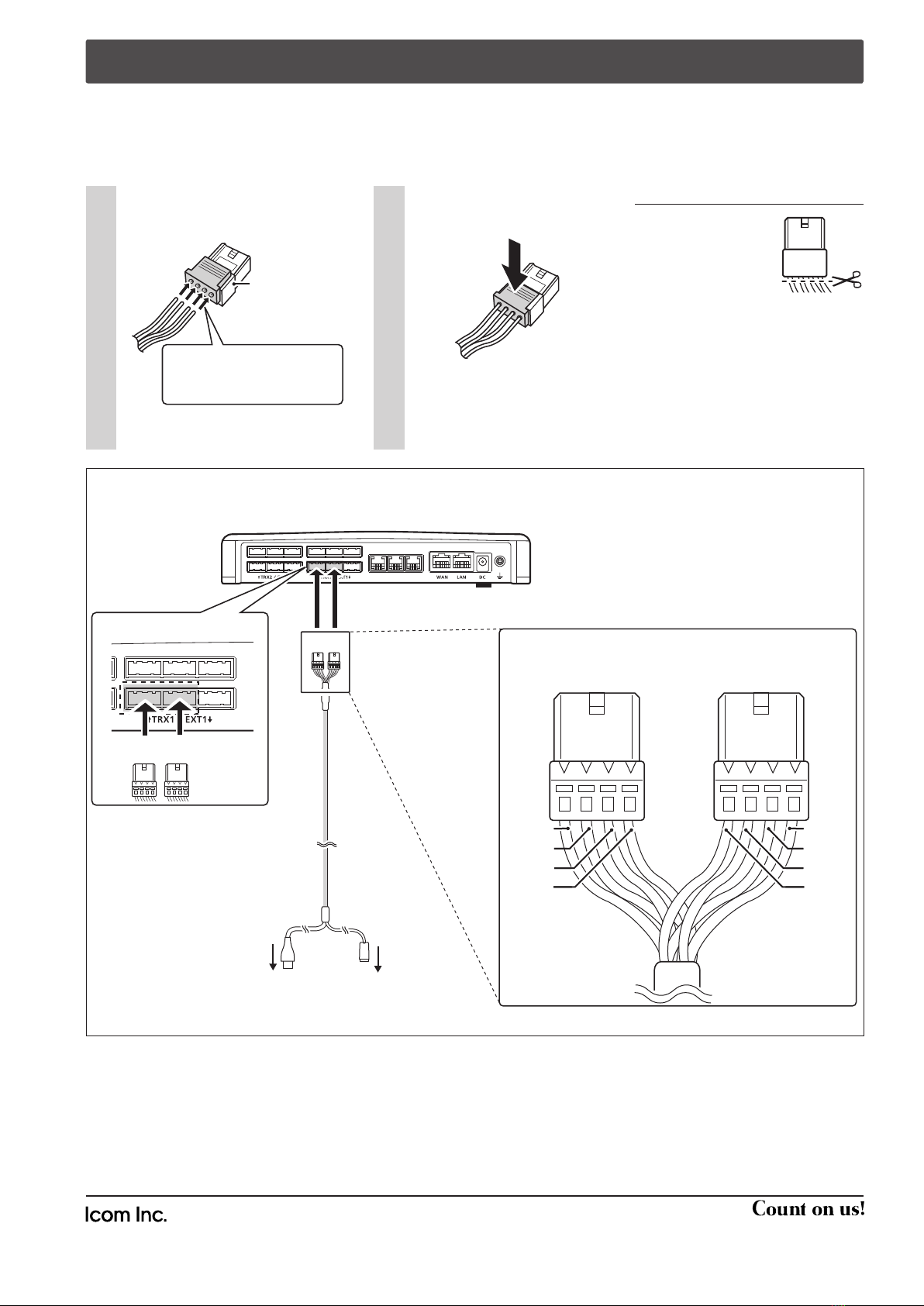
REPLACING THE CONNECTOR
If the cable becomes damaged, replace the connector(s). Make wire connections as described below.
• Spare connectors*1are supplied with the VE-PG3.
*1Manufacturer: DDK. Name: 232D-04S1B-DA5-FA (Equivalent to the OPC-2276 connector.)
The connector has two parts; a black base and a clear insert. DO NOT lock the connector parts before inserting all wires.
Insert the wires into the holes
according to the assigned pin
numbers.
1Press the clear insert down
until it locks in place.
2
Connector
(Supplied with
the VE-PG3)
Connector
(Supplied with
the VE-PG3)
Connector
(Supplied with
the VE-PG3)
The wires for each hole are
assigned by color. See the
illustration below.
OPC-2276
To the microphone To the speaker
• Turn OFF the VE-PG3 before connecting or disconnecting the OPC-2276.
• Follow the example to correctly connect the microphone and speaker to [EXT1] on the VE-PG3.
LINE2 LINE1
PHONE
BA
1234 1234
AB
YellowYellow
BrownBrown
WhiteWhite
GrayGray
BlackBlack
RedRed
BlueBlue
GreenGreen
Connector top (Expanded view)
VE-PG3 (Rear view)
VE-PG3 (Rear view)
AB
To [EXT1] (Lower slots)
OPC-2276 connection and wires assignment
RECOMMENDATION
If reconnecting is re-
peated about 30 times,
cut the wires*2 *3near
the connector and re-
place the connector.
*2Remove the cable from the VE-PG3,
before cutting the wires.
*3DO NOT cut the wires too short. Other-
wise it will be difficult to reconnect them
to the VE-PG3.
• After the insert is locked, it is
impossible to release it again.
Icom, Icom Inc. and the Icom logo are registered trademarks of Icom Incorporated (Japan) in Japan, the United States, the
United Kingdom, Germany, France, Spain, Russia and/or other countries.
A-7045X-1EX
Printed in Japan
© 2012 Icom Inc.
1-1-32 Kamiminami, Hirano-ku, Osaka 547-0003, Japan


