Icom IC-207H User manual

INSTRUCTION MANUAL
i207H
VHF/UHF FM TRANSCEIVER
This device complies with Part 15 of the FCC rules. Operation is sub-
ject to the following two conditions: (1) This device may not cause
harmful interference, and (2) this device must accept any interference
received, including interference that may cause undesired operation.

RWARNING! NEVER connect the transceiver to an
AC outlet. This may pose a fire hazard or result in an electric
shock.
RWARNING! NEVER operate the transceiver while
driving a vehicle. Safe driving requires your full attention—
anything less may result in an accident.
NEVER connect the transceiver to a power source of more
than 16 V DC. This connection will ruin the transceiver.
NEVER connect the transceiver to a power source using
reverse polarity. This connection will ruin the transceiver.
NEVER cut the DC power cable between the DC plug and
fuse holder. If an incorrect connection is made after cutting,
the transceiver might be damaged.
NEVER place the transceiver where normal operation of
the vehicle may be hindered or where it could cause bodily
injury.
NEVER let objects impede the operation of the cooling fan
on the rear panel.
DO NOT push the PTT when not actually desiring to transmit.
i
IMPORTANT
READ ALL INSTRUCTIONS carefully and completely before
using the transceiver.
SAVE THIS INSTRUCTION MANUAL—This instruction man-
ual contains important operating instructions for the IC-207H.
EXPLICIT DEFINITIONS
The explicit definitions below apply to this instruction manual.
CAUTIONS
WORD DEFINITION
RWARNING Personal injury, fire hazard or electric shock
may occur.
CAUTION Equipment damage may occur.
NOTE If disregarded, inconvenience only. No risk
of personal injury, fire or electric shock.

ii
UNPACKING
Accessories included with the transceiver: Qty.
➀DC power cable (OPC-346)............................................. 1
➁Mobile mounting bracket ................................................. 1
➂Microphone (HM-98*) ...................................................... 1
➃Fuse (20 A)...................................................................... 1
➄Knob bolt (M4 ×8) ........................................................... 4
➅Mounting bolt (M5 ×12)................................................... 4
➆Nut (M5)........................................................................... 4
➇Spring washer (M5) ......................................................... 4
➈Flat washer (M5).............................................................. 4
➉Self-tapping screws (A0 5 ×16)....................................... 4
*Some versions are supplied with the HM-96 instead.
DO NOT allow children to play with any radio equipment
containing a transmitter.
During mobile operation, DO NOT operate the transceiver
without running the vehicle’s engine. When transceiver power
is ON and your vehicle’s engine is OFF, the vehicle’s battery
will soon become exhausted.
BE CAREFUL! The transceiver will become hot when
operating it continuously for long periods.
AVOID using or placing the transceiver in areas with tem-
peratures below –10°C (+14°F) or above +60°C (+140°F) or
in areas subject to direct sunlight, such as the dashboard.
AVOID
the use of chemical agents such as benzine or alcohol
when cleaning, as they can damage the transceiver surfaces.
USE Icom microphones only (supplied or optional). Other
manufacturer’s microphones have different pin assignments
and may damage the transceiver if attached.
➀➁ ➂
➃
➄
➅➉
➆➇
➈
Note that in this manual, sections beginning with a
microphone icon (as at left) designate operation via
the HM-98 microphone.

TABLE OF CONTENTS
iii
IMPORTANT .................................................................................... i
EXPLICIT DEFINITIONS ................................................................. i
CAUTIONS ...................................................................................... i
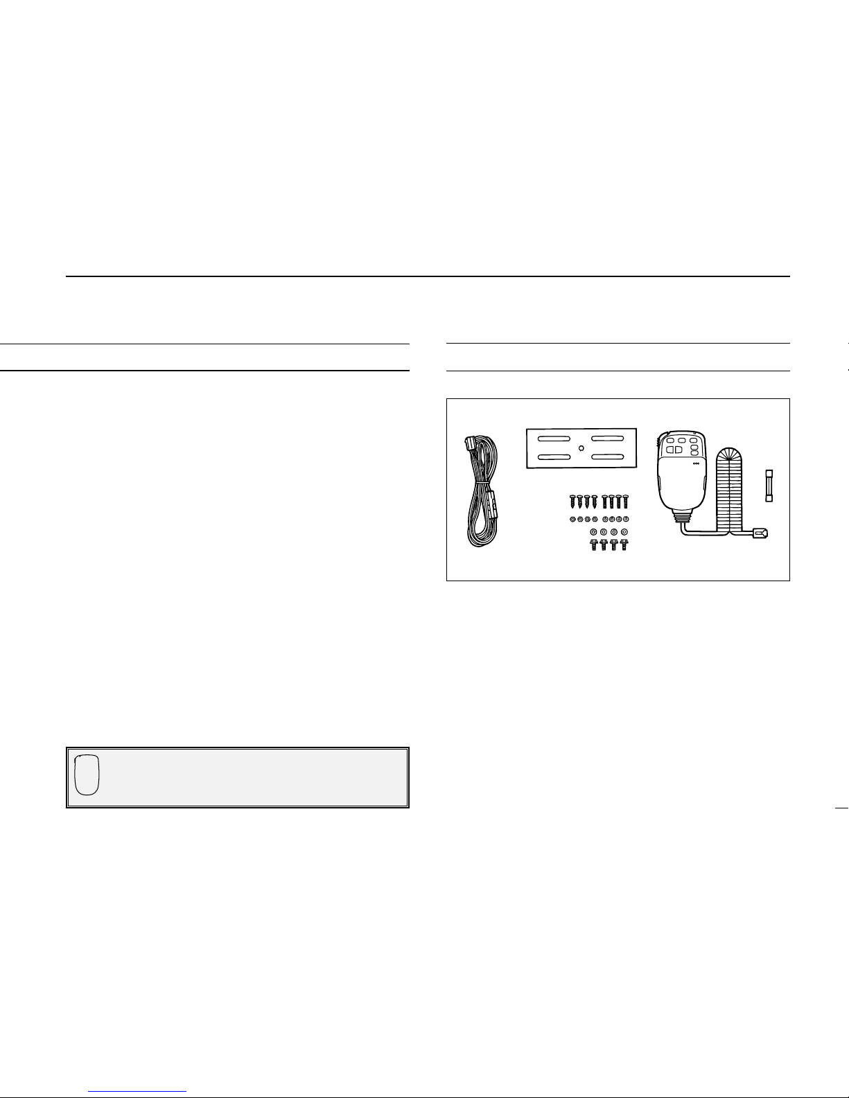
UNPACKING ................................................................................... ii
TABLE OF CONTENTS ................................................................. iii
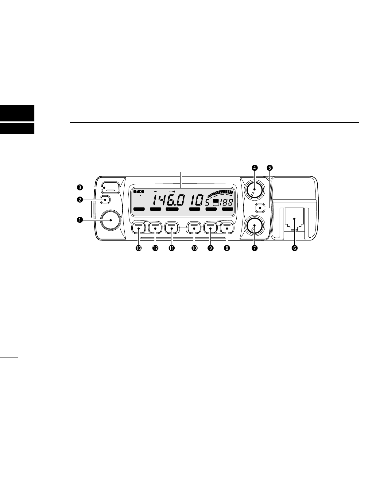
1 PANEL DESCRIPTION ....................................................... 1 – 8
■Front panel ........................................................................................... 1
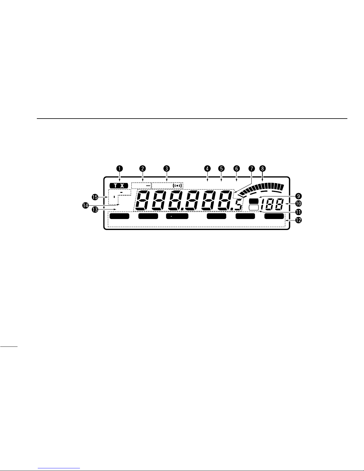
■Function display ................................................................................... 3
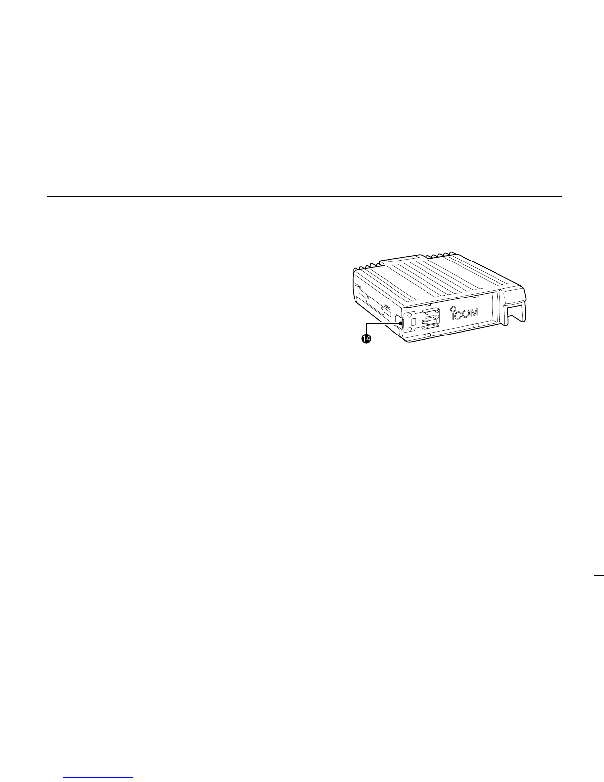
■Rear panel ............................................................................................ 5
■Microphone .......................................................................................... 6
■Microphone keypad .............................................................................. 7
2 INSTALLATION ................................................................. 9 – 14
■Installation methods ............................................................................. 9
■Location .............................................................................................. 10
■Single body installation ...................................................................... 10
■Microphone connection ...................................................................... 11
■Separate installation ........................................................................... 11
■Optional MB-58 installation ................................................................ 12
■Battery connection ............................................................................. 13
■DC power supply connection ............................................................. 13
■Antenna installation ............................................................................ 14
3 SETTING A FREQUENCY .............................................. 15 – 19
■Preparation ......................................................................................... 15
■Lock functions .................................................................................... 16
■Using the tuning dial ........................................................................... 17
■Using [Y]/[Z] switches ....................................................................... 17
■Tuning step selection ......................................................................... 18
■Using the keypad ............................................................................... 19
4 BASIC OPERATION ....................................................... 20 – 23
■Receiving ........................................................................................... 20
■Monitor function .................................................................................. 21
■Audio mute function ........................................................................... 21
■Avionics band receive ........................................................................ 21
■Transmitting ........................................................................................ 22
■Selecting the output power ................................................................. 22
■One-touch PTT function ..................................................................... 23
5 REPEATER OPERATION ............................................... 24 – 28
■Accessing a repeater ......................................................................... 24
■Subaudible tones ............................................................................... 26
■Offset frequency ................................................................................. 27
■Auto repeater ..................................................................................... 28
6 MEMORY OPERATION .................................................. 29 – 33
■General description ............................................................................ 29
■Memory channel selection ................................................................. 29
■Programming a memory channel ....................................................... 30
■Programming a memory channel via the microphone .......................... 31
■Transferring memory contents ........................................................... 32
■Memory clearing ................................................................................. 33
7 CALL CHANNEL OPERATION ...................................... 34 – 35
■Calling up a call channel .................................................................... 34
■Transferring call channel contents ..................................................... 34
■Programming a call channel ............................................................... 35
8 SCRATCH PAD MEMORY .............................................. 36 – 37
■What is a scratch pad memory? ......................................................... 36
■Calling up a scratch pad memory ....................................................... 36
■Transferring scratch pad memory contents ........................................ 37

iv
9 SCAN OPERATION ........................................................ 38 – 43
■Scan types ......................................................................................... 38
■Scan start/stop ................................................................................... 39
■Programming scan edges .................................................................. 40
■Programming scan edges via the microphone ................................... 41
■Skip channel setting ........................................................................... 42
■Scan resume condition ....................................................................... 43
10 PRIORITY WATCH .......................................................... 44 – 45
■Priority watch types ............................................................................ 44
■Priority watch operation ...................................................................... 45
11 DTMF MEMORY ENCODER .......................................... 46 – 49
■Programming a DTMF code ............................................................... 46
■Clearing the DTMF memory contents ................................................ 46
■Programming a DTMF code via the microphone ............................... 47
■Transmitting a DTMF code ................................................................. 48
■DTMF speed ...................................................................................... 49
12 POCKET BEEP AND TONE SQUELCH ........................ 50 – 52
■Pocket beep operation ....................................................................... 50
■Tone squelch operation ...................................................................... 51
■Tone scan ........................................................................................... 52
13 WIRELESS OPERATION ................................................ 53 – 58
■Connection ......................................................................................... 53
■HM-90
WIRELESS MICROPHONE
............................................................ 53
■EX-1759 installation ........................................................................... 54
■HM-90 switches .................................................................................. 55
■Microphone address ........................................................................... 58
14 OTHER FUNCTIONS ...................................................... 59 – 66
■Beep tones on/off ............................................................................... 59
■Time-out timer .................................................................................... 59
■Auto power-off .................................................................................... 60
■Cooling fan setting ............................................................................. 60
■Microphone [F-1]/[F-2] keys ............................................................... 61
■Display dimmer setting ....................................................................... 61
■Demonstration display ........................................................................ 62
■Squelch delay ..................................................................................... 62
■Packet operation ................................................................................ 63
15 MAINTENANCE .............................................................. 67 – 69
■Troubleshooting .................................................................................. 67
■Fuse replacement .............................................................................. 69
■Partial resetting .................................................................................. 69
■Resetting the CPU ............................................................................. 69
16 SPECIFICATIONS .................................................................. 70
17 OPTIONS ........................................................................ 71 – 72
18 MODE ARRANGEMENT ................................................ 73 – 74

PANEL DESCRIPTION
1
1
qTUNING DIAL
Selects the operating frequency (p. 17), the memory chan-
nel (p. 29), the contents of the set mode display and the
scanning direction. (p. 39)
wSELECT MEMORY/MEMORY WRITE SWITCH
[S.MW(MW)]
➥
Selects a memory channel for programming. (p. 30)
➥
Programs selected memory when pushed and held.
(p. 30)
eBAND SWITCH [BAND]
➥
Toggles between 144 and 430(440) MHz operation.
(p. 15)
➥
When a call channel is selected, this switch toggles be-
tween the 2 available call channels. (p. 34)
rVOLUME CONTROL [VOL]
Adjusts the audio level. (p. 20)
tPOWER SWITCH [PWR]
Turns power ON and OFF when pushed for 1 sec.
yMICROPHONE CONNECTOR
Connects the supplied microphone. (p. 11)
uSQUELCH CONTROL [SQL]
Varies the squelch level. (p. 20)
• RF attenuator activates and increases the attenuation when ro-
tated clockwise to the center position and further.
BAND
MW
S.MW
PWR
VOL
SQL
DTMFDUP LOCK
SET
BUSYAOTOTDATATDUP SQL
MONILOW
PRIO T SCAN
M⁄CALL TONE
SCAN
V⁄MHz
MUTE
PRIOLO
MID H I
M
SKIP
19
5
Function display (p. 3)
■Front panel

1
PANEL DESCRIPTION
2
iSET/LOCK SWITCH [SET(LOCK)]
➥
Selects SET mode when pushed. (p. 70)
➥
Toggles the lock function ON and OFF when pushed
and held. (p. 16)
oMONITOR/DTMF SWITCH [MONI(DTMF)]
➥
Toggles squelch opened and closed when pushed.
(pgs. 20, 24)
➥
Turns the DTMF memory encoder ON and OFF for auto
patch operation when pushed and held. (p. 46)
!0 OUTPUT POWER/DUPLEX SWITCH [LOW(DUP)]
➥
Each push changes the output power selection. (p. 22)
•There are 4 output powers available: low, mid-low, mid-high
and high.
➥
Push and hold to select a duplex setting. (p. 24)
•There are 3 duplex settings available: minus duplex (“– DUP”
appears, plus duplex (“+ DUP”appears) and simplex.
!1 TONE/TONE SCAN SWITCH [TONE(T-SCAN)]
➥
Each push selects a tone function. (p. 50)
•Tone encoder, pocket beep, tone squelch or tone function
OFF can be selected.
➥
Push and hold to start/stop the tone scan function.
(p. 52)
!2 MEMORY/CALL CHANNEL SWITCH [M/CALL(PRIO)]
➥
Selects and toggles memory mode or a call channel
(pgs. 29, 34)
➥
Activates the priority watch function when pushed and
held. (p. 44)
!3 VFO/MHz SWITCH [V/MHz(SCAN)]
➥
Selects and toggles VFO mode and 1 MHz tuning dis-
play. (p. 17)
➥
Starts a scan when pushed and held. (p. 39)
!4 FRONT PANEL RELEASE LATCH
While pushing this latch, slide the front panel to the left to
remove it.

1PANEL DESCRIPTION
3
qTRANSMIT INDICATOR (p.22)
➥
Appears while transmitting.
➥
Flashes while transmitting with the one-touch PTT func-
tion (p. 23).
wDUPLEX INDICATORS (p. 24)
“DUP–” or “DUP”appears during semi-duplex operation
(repeater operation).
eTONE INDICATORS
➥
“T”appears while the subaudible tone encoder is in
use. (p. 26)
➥
“T SQL”appears while the tone squelch function is in
use. (p. 51)
➥
“T SQLS”appears while the pocket beep function is
in use. (p. 50)
rTOT (TIME-OUT TIMER) INDICATOR (p. 59)
Appears while the time-out timer has been activated.
tAUTO POWER-OFF INDICATOR (p. 60)
Appears while the auto power-off function is in use.
yBUSY INDICATOR (p. 20)
Appears while a signal is being received or the squelch is
open ([MONI] is being pushed).
uFREQUENCY READOUT
Shows the operating frequency, set mode contents, etc.
•The decimal point of the frequency flashes while scanning.
(p. 39)
•“d”appears in place of the 100 MHz digit while the DTMF mem-
ory function is in use.
DTMFDUP LOCK
SET
BUSYAOTOTTDUP SQL
MONILOW
PRIO T SCAN
M⁄CALL TONE
SCAN
V⁄MHz
MUTE
PRIOLO
MID H I
M
SKIP
19
5
■Function display

4
1
PANEL DESCRIPTION
iS/RF INDICATORS (p. 22)
➥
Show the relative signal strength while receiving sig-
nals.
➥
Show the output power while transmitting.
oMEMORY INDICATOR (p. 15)
Appears when memory mode is selected.
!0 MEMORY CHANNEL READOUTS
➥
Show the selected memory channel numbers.
➥
A capital “L”appears while the frequency lock function
is in use. (p. 16)
➥
“C1”or “C2”appears while on a call channel. (p. 34)
➥
One of “L1–L5”appears when a scratch pad memory is
selected. (p. 36)
➥
One of “r1–r5”appears when a duplex scratch pad
memory is selected. (p. 36)
➥
A small “c”appears when VFO mode is selected from
the call channel or a scratch pad memory. (pgs. 34, 37)
!1 SKIP INDICATOR (p. 42)
Appears when the displayed memory channel is specified
as a skip channel.
!2 SWITCH INDICATORS
Indicate the function(s) of the front panel switches directly
below the function display.
!3 AUDIO MUTE INDICATOR (p. 56)
Appears when the audio mute function is activated via mi-
crophone control.
•This function is cancelled when any switch or control is operated.
!4 PRIORITY WATCH INDICATOR (p. 45)
Appears while the priority watch is activated; flashes while
the watch is paused.
!5 OUTPUT POWER INDICATORS (p. 22)
➥
“LO”appears for low output power. (5 W)
➥
“MID-LO”appears for mid-low output power. (10 W)
➥
“MID-HI”appears for mid-high output power. (20 W)
➥
“HI”appears for high output power.
(50 W VHF; 35 W UHF)

1PANEL DESCRIPTION
5
■Rear panel
q
w
r
e
qANTENNA CONNECTOR [ANT]
Accepts a 50 Ωdual band antenna with a PL-259 connec-
tor. (p. 14)
wSPEAKER JACK [SP]
Connects a 4–8 Ωspeaker, if required. Outputs the se-
lected band’s audio.
eDATA JACK [DATA]
6-pin mini DIN jack to connect a TNC, etc. for packet op-
eration.
NOTE: The connection between this jack and the TNC
differs depending on whether 1200 bps or 9600 bps op-
eration is chosen in initial set mode (p. 63). See right
for pin assignments.
rPOWER RECEPTACLE [DC13.8V]
Accepts 13.8 V DC with the supplied DC power cable.
DDATA JACK PIN ASSIGNMENTS
qDATA IN (1200 bps: AFSK
9600 bps: G3RUH,
GMSK)
wGND
ePTTP
rDATA OUT (9600 bps)
tAF OUT (1200 bps)
ySQ
qDATA IN
Input terminal for data transmit. See p. 63 for details on
how to toggle data speed between 1200 and 9600 bps.
wGND
Common ground for DATA IN, DATA OUT and AF OUT.
ePTTP
PTT terminal for packet operation only. Connect ground to
transmit data.
rDATA OUT
Data out terminal for 9600 bps operation only.
tAF OUT
Data out terminal for 1200 bps operation only.
ySQ (squelch out)
Becomes high (+5V) when the transceiver receives a sig-
nal which opens the squelch.
•To avoid unnecessary TNC transmission, connect squelch to the
TNC to inhibit transmission when receiving signals.
•Keep audio output at a normal level, otherwise a “SQ”signal will
not be output.

1
PANEL DESCRIPTION
6
■Microphone (HM-98*)
LOCK
VFO
CALL
MR
SUB
BAND
MW
FUNC
A
CLR
D-OFF
B
SET
PTT-M
3
PRIO
DTMF
6
LOW
AFC-OFF
2
SCAN
CSQL
5
MID
AFC
1
MONI
PGR
4
HIGH
T-OFF
C
ENT
TSQL
9
SIMP
16
KEY LOCK
#
TSQLS
8
DUP+
TONE-2
0
TONE
7
DUP
TONE-1
F-2
F-1
DTMF-S
MUTE
D
SQLSQLVOLVOL
Mic element
qUP/DOWN SWITCHES [Y]/[Z]
➥Push either switch to change the operating frequency,
memory channel, set mode contents, etc. (pgs. 17, 29)
➥Push and hold either switch to start scanning. (p. 39)
wPTT SWITCH
➥Push and hold to transmit; release to receive. (p. 22)
➥Toggles between transmitting and receiving while the
one-touch PTT function is in use. (p. 23)
eVFO SWITCH [VFO(LOCK)]
➥Push to select VFO mode.
➥Push and hold to toggle the lock function ON and OFF.
rMEMORY SWITCH [MR(CALL)]
➥Push to select memory mode. (p. 29)
➥Push and hold to select the call channel. (p. 34)
tACTIVITY INDICATOR
Lights red while a key is pushed; lights green while the
one-touch PTT function is in use.
yBAND SWITCH
Push to toggle the operating band. (p. 15)
uFUNCTION SWITCHES [F-1]/[F-2] (p. 61)
Assign your desired key function from the front panel
switches.
•Default settings are [LOW] for [F-1] and [TONE] for [F-2].
iFUNCTION INDICATOR
➥Lights orange while [FUNC] is activated—indicates the
secondary function of switches can be accessed.
➥Lights green when [DTMF-S] is activated—DTMF sig-
nals can be transmitted with the keypad. (p. 48)
oKEYPAD
Used for controlling the transceiver, transmitting a DTMF
encoder, etc. See the following 2 pages for details.
*Some versions are supplied with the HM-96 instead.

1PANEL DESCRIPTION
7
■Microphone keypad
FUNCTION SECONDARY FUNCTION (after )
FUNC
OTHER FUNCTIONS
Toggles between opening and closing the
operating band’s squelch. (p. 21)
No secondary function.
After :
Transmit the appropriate
DTMF code or push [0] to
[9], [A] to [D] to transmit
the DTMF memory con-
tents when the DTMF
memory encoder is acti-
vated. (p. 48)
DTMF-S
Starts and stops scanning. (p. 39) No secondary function.
Starts and stops priority watch. (p. 45) Turns the one-touch PTT function ON and
OFF. (p. 23)
Selects high output power. (p. 22) No secondary function.
Selects mid-high output power. (p. 22) No secondary function.
Selects low output power. (p. 22) Turns the DTMF memory encoder function
ON. (p. 47)
Selects –duplex. (p. 25) Turns the subaudible tone encoder ON.
(p. 25)
Selects +duplex. (p. 25) Turns the pocket beep function ON. (p. 50)
Selects simplex (p. 25) Turns the tone squelch function ON. (p. 51)
Increases the audio output. (p. 20)
•The [VOL] control on the front panel has prior-
ity when rotated.
While being pushed, transmits a 1750 Hz
tone. (p. 25)
AFC
1
MONI
AFC-OFF
2
SCAN
PTT-M
3
PRIO
PGR
4
HIGH
CSQL
5
MID
DTMF
6
LOW
TONE
7
DUP–
TSQLS
8
DUP+
TSQL
9
SIMP
TONE-2
0
VOL
KEY

1
PANEL DESCRIPTION
8
KEY FUNCTION SECONDARY FUNCTION (after )
FUNC
OTHER FUNCTIONS
•Clears a digit before entry. (p. 19)
•Cancels the scan, priority watch or DTMF
memory function. (pgs. 39, 45, 48)
•Writes the VFO contents into the memory
channel or call channel. (pgs. 31, 35)
•Advances the memory channel number
when continuously pushed after program-
ming is completed. (p. 31)
[A] to [D] transmit DTMF
memories. (p. 48)
Enters set mode and advances the set
mode selection order.
DTMF memory OFF.
•Sets the keypad for numeral input.
(p. 19)
•Decreases the set mode selection order
after entering set mode.
Turns the subaudible tone encoder, pocket
beep or tone squelch OFF. (pgs. 25, 50, 51)
Increases the squelch level. (p. 20)
•The [SQL] control on the front panel has prior-
ity when rotated.
Mutes the operating band’s audio. (p. 21)
•Mute function is released when any operation is
performed.
Decreases the squelch level. (p. 20)
•The [SQL] control on the front panel has prior-
ity when rotated.
Locks the digit keys on the keypad (including
the A–D, # and Mkeys. (p. 16)
Decreases the audio output. (p. 20)
•The [VOL] control on the front panel has prior-
ity when rotated.
Sends a 1750 Hz tone signal for 0.5 sec.
(p. 25)
MW
A
CLR
D-OFF
B
SET
16
KEY LOCK
#
SQL
T-OFF
C
ENT
MUTE
D
SQL
TONE-1
M
VOL
After :
Transmit the appropriate
DTMF code. (p. 48)
DTMF-S

DSeparate installation
•Optional OPC-600
SEPARATION CABLE
(3.5 m; 11.5 ft) or
OPC-601 (7.0 m; 23.0 ft) is necessary.
•Optional MB-58
REMOTE CONTROLLER BRACKET
is available
for front panel mounting.
•Optional MB-65
MOUNTING BASE
is available for increasing
front panel mounting possibilities (MB-58 is necessary).
•Optional OPC-440
MICROPHONE CABLE
(5.0 m; 16.4 ft) and
OPC-647 (2.5 m; 8.2 ft) are available to extend the micro-
phone cable.
•Optional OPC-441
SPEAKER CABLE
(5.0 m; 16.4 ft) is avail-
able to extend the speaker cable.
INSTALLATION
2
9
■Installation methods
DSingle body installation
•It is not necessary to purchase a mounting bracket. The
supplied mounting bracket (or optional MB-17A) can be
used for installation.
Main body
Front panel

2
INSTALLATION
10
■Location
Select a location which can support the weight of the trans-
ceiver and does not interfere with driving in any way. We rec-
ommend the locations shown in the diagram below.
■Single body installation
➀Drill 4 holes where the mounting bracket is to be installed.
•Approx. 5.5–6 mm (3⁄16 in) when using nuts; approx. 2–3 mm (1⁄16
in) when using self-tapping screws.
➁Insert the supplied screws, nuts and washers through the
mounting bracket and tighten.
➂Adjust the angle for the clearest view of the function dis-
play.
NEVER place the transceiver or remote controller where
normal operation of the vehicle may be hindered or where
it could cause bodily injury.
NEVER place the transceiver or remote controller where
air bag deployment may be obstructed.
DO NOT place the transceiver or remote controller where
hot or cold air blows directly onto it.
AVOID placing the transceiver or remote controller in di-
rect sunlight.
•EXAMPLE INSTALLATION LOCATIONS
Nut
Spring washer
Spring
washer
When using
self-tapping
screws
Flat washer
Mounting
bracket
Flange
bolt
20°

2INSTALLATION
11
■Microphone connection
The microphone connector is located behind the front panel.
Connect the supplied microphone as follows:
➀Slide the supplied microphone cable connector (and at-
tached microphone) into the microphone jack on the main
body of the transceiver until it clicks into place.
➁To remove the microphone, push the release lever on the
bottom of the microphone cable connector.
■Separate installation
Using an optional OPC-600/601
SEPARATION CABLE
, the front
panel can be separated from the main body, doubling as a re-
mote controller.
➀Detach the front panel as
at right.
➁Connect a separation
cable between the front
panel and main body
using the supplied screws
as illustrated below.
Connect microphone
here
Rear of front panel Main body
OPC-600 or OPC-601
➀8 V OUT
➁Freq. up/down
➂8 V control IN
➃PTT
➄Mic AF (–)
➅Mic AF (+)
➆Ground
➇Data IN
➇➀
Microphone pin assignments

2
INSTALLATION
12
■Optional MB-58 installation
The optional MB-58
REMOTE CONTROLLER BRACKET
is avail-
able for separate installation.
➀Drill 2 or 4 holes where the bracket or mounting base is to
be installed, respectively.
•Approx. 4 mm (1⁄8in) when using nuts; approx. 1–2 mm (1⁄16 in)
when using self-tapping screws.
➁Insert the supplied screws, bolts and washers through the
mounting base and tighten.
➂Adjust the angle for the clearest view of the function dis-
play and tighten 2 screws when the mounting base is used.
Bracket
When using self-
tapping screws.
Mounting
base
Mounting
bolt
➃Attach the supplied Velcro pads (large) to the remote con-
troller and bracket.
➄Attach the supplied Velcro pad (small) or rubber pad to the
bracket as shown below; then attach the remote controller.
DWhen using the MB-65
;
;
;
;;
;;
;;
;;
;;
;;;;
;;;;
MB-58 IC-207H remote controller
;
;
MB-58
MB-65
Adjust the viewing
angle for maximum
visibility of the func-
tion display.

2INSTALLATION
13
■Battery connection ■DC power supply connection
Use a 13.8 V DC power supply with more than 12 A capabil-
ity. An optional IC-PS30
DC POWER SUPPLY
is available for
using the transceiver with a DC power supply in your home.
Make sure the ground terminal of the DC power supply is
grounded.
NEVER connect the transceiver directly to a 24 V battery.
DO NOT use the cigarette lighter socket for power con-
nections.
Attach a rubber grommet when passing the DC power
cable through a metal plate to prevent short circuits.
•CONNECTING TO A DC POWER SOURCE
See p. 69 for fuse replacement.
Fuses
20 A
black
red⊕
red
Grommet
⊕
−
black
−
12 V
Supplied
DC power cable
•CONNECTING TO A DC POWER SUPPLY
See p.69 for fuse replacement.
DC power
supply 13.8 V
to an
AC
outlet
Fuses
20 A
black
red⊕
−
⊕
−

2
INSTALLATION
14
■Antenna installation
DAntenna location
To obtain maximum performance from the transceiver, select
a high-quality antenna and mount it in a good location. A non-
radial antenna should be used when using a magnetic mount.
DAntenna splitter
You can use a dual band antenna because a duplexer is in-
stalled in the transceiver. However, an external duplexer must
be connected when using a separate antenna for each band.
DAntenna connector
The antenna uses a PL-259 connector.
30 mm
10 mm (soft solder)
10 mm
1–2 mm
solder solder
Soft
solder
Coupling ring
•PL-259 CONNECTOR
➀
➂
➃
➁
Slide the coupling ring
down. Strip the cable
jacket and soft solder.
Slide the connector
body on and solder it.
Screw the coupling
ring onto the connec-
tor body.
Strip the cable as
shown at right. Soft
solder the center con-
ductor.
(10 mm ≈3⁄8 in)
Roof-mount antenna
(Drill a hole or use a magnetic mount.)
Gutter-mount antenna
Trunk-mount
antenna

SETTING A FREQUENCY
3
15
■Preparation
DTurning power ON/OFF
Push [PWR] for 1 sec. to turn power ON or OFF.
DOperating band
The IC-207H can receive/transmit on the 144 MHz and
430(440) MHz bands, or receive only on the avionics band
(USA version only).
Push [BAND] one or more times to select the desired operat-
ing band.
•The frequency changes to indicate the selected band.
•The operating band cannot be changed unless you are in VFO
mode (see right).
Push [BAND] one or more times to select the de-
sired operating band.
DVFO and memory modes
The transceiver has 2 normal operating modes: VFO mode
and memory mode.
Push [V/MHz] to select VFO mode when the transceiver is
not in VFO mode.
•If VFO mode is already selected, the digits below 100 kHz disap-
pear. In this case, push [V/MHz] again (or push twice depending on
version).
Push [VFO] to select VFO mode.
Push [PWR] for 1 sec.
BAND
Appears when memory mode
is selected.
VFO mode is selected.
HI 19
5HI 19
5
d
VFO
Other manuals for IC-207H
3
Table of contents
Other Icom Transceiver manuals

Icom
Icom IC-7200 Setup guide

Icom
Icom IC-M25 User manual

Icom
Icom IC-A4 User manual

Icom
Icom IC-M90 User manual

Icom
Icom IC-F3160 SERIES User manual

Icom
Icom IC-P2A User manual

Icom
Icom IC-7100 Installation and operating instructions

Icom
Icom IC-F3201DEX Installation guide

Icom
Icom IC-F21 User manual

Icom
Icom IC-V82 User manual

Icom
Icom IC-F61-L User manual

Icom
Icom IC-T2H User manual

Icom
Icom IC-2iA User manual

Icom
Icom IC-2000 User manual

Icom
Icom IC-706MKIIG User manual

Icom
Icom IC-7610 Installation guide

Icom
Icom IC-F9010 SERIES User manual

Icom
Icom IC-746PRO User manual

Icom
Icom IC-7851 User manual

Icom
Icom F6220D 16 USA User manual