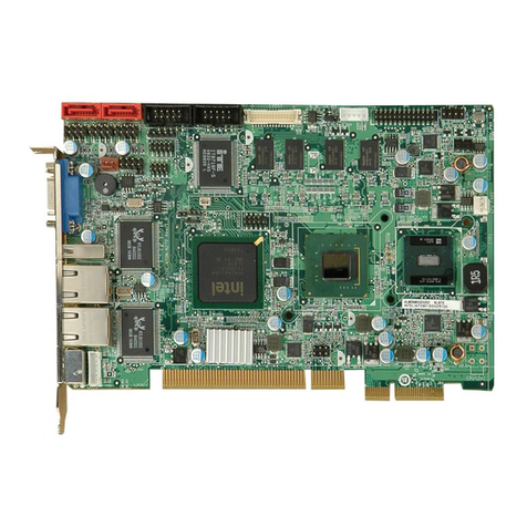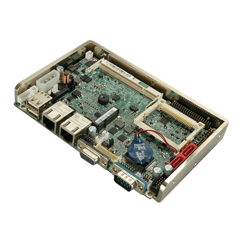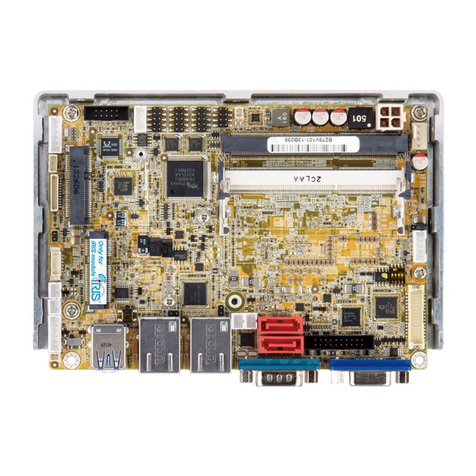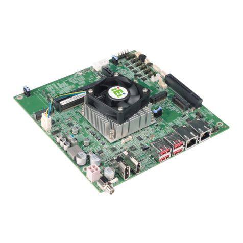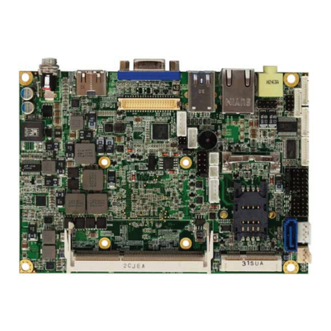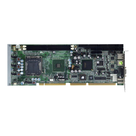
WAFER-ULT/ULT2-i1 3.5" SBC
Page vi
3.2.9 Internal DisplayPort Connector...................................................................... 27
3.2.10 IPMI LED Connector..................................................................................... 28
3.2.11 iRIS Module Slot............................................................................................. 28
3.2.12 Keyboard and Mouse Connector ................................................................... 29
3.2.13 LAN LED Connectors.................................................................................... 31
3.2.14 LVDS Backlight Control Connector............................................................... 31
3.2.15 LVDS Connector ............................................................................................ 32
3.2.16 PCIe Mini Card Slot ...................................................................................... 34
3.2.17 Power and HDD LED Connector.................................................................. 35
3.2.18 Power Button Connector................................................................................ 36
3.2.19 Reset Button Connector ................................................................................. 37
3.2.20 SATA 6Gb/s Connectors................................................................................. 38
3.2.21 Serial Port Connector, RS-232....................................................................... 39
3.2.22 Serial Port Connector, RS-422/485................................................................ 40
3.2.23 SMBus Connector .......................................................................................... 41
3.2.24 SO-DIMM Slots.............................................................................................. 42
3.2.25 SPI Flash Connector...................................................................................... 43
3.2.26 System Fan Connector................................................................................... 43
3.2.27 USB 2.0 Connector ........................................................................................ 44
3.3 EXTERNAL INTERFACE CONNECTORS....................................................................... 45
3.3.1 Ethernet Connectors ........................................................................................ 46
3.3.2 USB 3.0 Ports................................................................................................... 46
3.3.3 Serial Port Connector (COM1) ....................................................................... 47
3.3.4 VGA Connector................................................................................................ 48
4 INSTALLATION ......................................................................................................... 49
4.1ANTI-STATIC PRECAUTIONS...................................................................................... 50
4.2 INSTALLATION CONSIDERATIONS.............................................................................. 50
4.3 SO-DIMM INSTALLATION ....................................................................................... 52
4.4 IRIS-1010 MODULE INSTALLATION.......................................................................... 52
4.5 FULL-SIZE PCIE MINI CARD INSTALLATION............................................................. 54
4.6 HALF-SIZE PCIE MINI CARD INSTALLATION............................................................. 56
4.7 SYSTEM CONFIGURATION......................................................................................... 58
4.7.1 DC 5V Jumper for LVDS Backlight Dimming ................................................. 59
4.7.2 AT/ATX Power Mode Selection........................................................................ 60
