IME adeunis TEMP Sigfox RC1 User manual

User Guide - TEMP - Sigfox RC1 1
User Guide - TEMP - Sigfox RC1
Published
Category SIGFOX SENSOR
Document version V3.1.1
Language EN
Type User Guide
Product/Service TEMP / TEMP2S EU868 / RC1
https://s3-us-west-2.amazonaws.com/secure.notion-static.com/00e5f77c-913
9-455d-9f4a-e3aa1c618807/User_Guide_TEMP_IP68_Sigfox_RC1_V3.1.1_
(1).pdf
www.ime.de

User Guide - TEMP - Sigfox RC1 2
💡
This document applies to the following products :
TEMP V4 IP68 Sigfox 863-870 ambient probe and remote probe
TEMP V4 IP68 Sigfox 863-870 TEMP two external probes
Part number:
ARF8180BCA
ARF8180BCB
Firmware version:
RTU version: V02.00.01
APP version: V02.01.00
Document Information
Title TEMP IP68 Sigfox 863-870 - User Guide
Document type User Guide
Version 3.1.1
DOCUMENTATION GUIDE
PREAMBLE
DISCLAIMER
TECHNICAL SUPPORT
RECOMMENDATIONS
INTRODUCTION
https://s3-us-west-2.amazonaws.com/secure.notion-static.com/66a0b375-e64
4-452c-b81e-c83e406a789e/EU_declaration_of_conformity(_TEMP_Sigfox_
ARF8181xx).pdf
PRODUCTS AND REGULATORY
INFORMATION
www.ime.de

User Guide - TEMP - Sigfox RC1 3
1. PRODUCT PRESENTATION
1.1. General description
1.2. Dimensions
1.3. Electronic board
1.4. Two versions of the product
1.5. Technical specifications
1.5.1 General characteristics
1.5.2 Electric characteristics
1.5.3 Probes characteristics
1.5.4 Autonomy
1.5.5 Environmental conditions and ingress protection
2. PRODUCT OPERATION
2.1. Global operation
2.1.1 PARK mode
2.1.2 COMMAND mode
2.1.3 PRODUCTION mode
2.1.4 Low battery management
2.2. Transmission modes
2.2.1 Periodical transmission with or without historisation
2.2.2 Periodical transmission with redundancy
2.2.3 Transmission on threshold overpassed
2.2.4 Transmission on threshold overpassed with alarm repetition
2.2.5 Transmission of the Keep Alive frame
2.3. Operation of the LED
3. REGISTERS AND FRAME DESCRIPTION
4. CONFIGURATION AND INSTALLATION
4.1. Configuration and installation of the transmitter
4.2. Installation of the remote probe
5. WIRING
5.1. Disconnect a probe
5.2. Wiring a probe
5.3. Wiring external supply
DOCUMENT HISTORY
TABLE OF CONTENTS
PRODUCTS AND REGULATORY INFORMATION
www.ime.de

User Guide - TEMP - Sigfox RC1 4
IMPORTANT NOTE: The TEMP V4 IP68 Sigfox RC1 can be started with a magnet
or switching the product in PRODUCTION mode with the IoT Configurator.
Description :
• The TEMP IP68 Sigfox RC1 is a ready-to-use radio device enabling temperatures
to be measured and transmitted by wireless communication network.
• This product exists in 2 versions: one including an ambient probe and a remote
probe and a second one with two remote probes.
• These two products answer the users need to monitor the temperature (ambient or
contact) of a storage room, cold room or all rooms needing a product able to
withstand more or less harsh environment.
• The use of the Sigfox RC1 protocol allows the user to integrate the TEMP IP68
Sigfox RC1 into any network that is already deployed.
• The product emits the data from the sensors either periodically or in an event-
based way based on top and/or bottom thresholds.
• The configuration of the transmitter is accessible by the user via a micro-USB port
or via the network, allowing in particular a choice of modes of transmission,
periodicity or triggering thresholds.
• The TEMP IP68 Sigfox RC1 is powered by a replaceable internal battery and/or an
external supply.
• The TEMP IP68 Sigfox RC1 is compatible with the KARE+ service.
Composition of the package
The product is supplied in a cardboard box containing the following items:
top casing, electronic card, casing base plate, 2 screws for the plate, cable gland, 3
gland seals, 2 CBLZ 2.2 x 19mm screws, 2 Fischer SX4 plugs, Removable LiSOCl2
FANSO (battery-pack ER18505H+W36+51021)
1. PRODUCT PRESENTATION
www.ime.de

User Guide - TEMP - Sigfox RC1 5
1.1. General description
www.ime.de

User Guide - TEMP - Sigfox RC1 6
1.2. Dimensions
Values in millimeters
www.ime.de

User Guide - TEMP - Sigfox RC1 7
1.4. Two versions of the product
Product with ambient probe and remote probe:
1.3. Electronic board
www.ime.de

User Guide - TEMP - Sigfox RC1 8
Product with two external probes:
1.5. Technical specifications
1.5.1 General characteristics
Parameters Value
Working temperature -25°C / +70°C
Dimensions 132 x 62 x 34mm
Weight 148g 1 Remote probe, 185g 2 remote probes
Casing IP 68
Radio standards EN300220-1 et EN300220-2
www.ime.de

User Guide - TEMP - Sigfox RC1 9
Parameters Value
Sigfox network EU863-870
Max power transmission 14 dBm
1.5.2 Electric characteristics
Supply Characteristics Value Unit
Battery FANSO
ER18505H+W36mm+51021
connector :
Voltage 3.6 V
Battery FANSO
ER18505H+W36mm+51021
connector :
Current max 150 mA
External : Input range 4.5 to 6.5 V
External : Current max 110 mA
USB Tension 5 V
USB Courrent max 110 mA
The external power supply chosen must comply with the above electrical
characteristics and must conform to the standards EN/IEC 62368-1 and EN 61000-
3-2, EN 61000-4-2, EN 61000-4-4, EN 61000-4-5.
Example of reference tested by adeunis and functional with the product by cutting
the wires: GS05E-USB - Wall Mount AC Adapters 5W 5V 1A W/Euro Plug
WallMount USB Output from Mean well.
1.5.3 Probes characteristics
Characteristics
Ambient probe - temperature range [-25°C /+70°C]
Remote probe - sensor temperature range 55°C..+155°C
Remote probe - wire temperature range 30°C+105°C
Remote probe - wire length 2m
Precision [0°C/+60°C] +/- 0,2°C
Precision [-35°C/0°C] +/- 0,5°C
Precision [-55°C/-35°C] -0,6 /+0,8°C
www.ime.de

User Guide - TEMP - Sigfox RC1 10
Characteristics
Precision [+60°C/105°C] +/- 2°C
CAUTION: Allow a few minutes for the probe to come back to room temperature
before any manual operations to avoid mechanical damages. In addition, please
respect the minimum and maximum temperatures for the sensor and the wire (cf.
Table here-above).
1.5.4 Autonomy
Usage conditions :
Product storage before use: 1 year maximum.
Calculations made with a temperature at 20°C and 1downlink per day
Nb of frame per day Sampling (minutes) Event per day Autonomy (years)
2 10 0 9.8
2 10 10 4.1
2 60 0 >10
2 60 10 4.2
24 10 0 2.4
24 10 10 1.8
24 60 0 2.4
24 60 10 1.8
48 10 0 1.3
48 10 10 1.1
48 60 0 1.3
48 60 10 1.1
144 10 0 <1
144 10 10 <1
144 60 0 <1
144 60 10 <1
Values above are estimations done under certain conditions of use and environment.
They do not represent in any case a commitment on the part of Adeunis.
www.ime.de

User Guide - TEMP - Sigfox RC1 11
1.5.5 Environmental conditions and ingress protection
The casing of the TEMP V4 IP68 Sigfox RC1 has been tested to ensure a certain
level of dust and water protection.
For dust: level 6 guarantees complete sealing against
For water: level 8 guarantees at least a complete waterproof casing for more
than 1 hour in one meter deep.
The tests carried out by Adeunis for the immersion were under the following
conditions: immersion for 10 hours at a depth of 1 meter in water at room
temperature (around 20 ° C) followed by an immersion for one hour in water at 60
°C.
We can therefore guarantee the waterproofness of our IP68 case for immersions
less than or equal to these times. Any use of our sensor outside the criteria
mentioned above cannot be guaranteed by Adeunis.
Important: the degree of protection IP68 does not, in any way, guarantee protection
against condensation linked to ambient humidity and temperature variations. Large
variations in temperature and / or prolonged high relative humidity can lead to an
early end of product life.
Depending on the mission profile of your product, we advise you to contact us.
2. PRODUCT OPERATION
2.1. Global operation
IMPORTANT NOTE : Adeunis use the most significant byte first format.
The product has several operating modes:
www.ime.de

User Guide - TEMP - Sigfox RC1 12
2.1.1 PARK mode
The product is delivered in PARK mode, it is in standby mode and its consumption is
minimal. To switch the product out of the Park* Mode pass a magnet across it for a
duration higher than 5 seconds. The green LED illuminates to indicate the detection
of the magnet and then flashes quickly during the product starting phase.
The device then sends its configuration and data frames.
2.1.2 COMMAND mode
This mode allows the user to configure the registers of the product.
To enter in this mode, plug the micro-USB cable and use the IoT configurator or AT
command. Exit from command mode is done when USB is disconnected or with an
ATO command. The product will return in its previous state, PARK or
PRODUCTION.
2.1.3 PRODUCTION mode
This mode allows the user to operate the product in its finale use.
2.1.4 Low battery management
When the product detect that the battery is not able to deliver the level of power
required for a emission (extreme temperature or end-of-life of the battery), it waits to
be able to transmit. If it detect that the generated delay is longer than 1 minute, it
informs the user activating the “lowbattery” flag in the status byte of each frame sent.
www.ime.de

User Guide - TEMP - Sigfox RC1 13
The “battery low” flag is automatically disappearing when the battery is replaced or
when temperature conditions are favorable to the proper functioning of the battery.
2.2. Transmission modes
The product allows to measure temperature on 2 probes or 1 probes only, to save
the information and to send it according to 3 modes of emission.
Periodical
transmission
Over threshold
transmission
Periodical and over
threshold transmission
Definition :
The periodical
transmission
allows the
temperature to be
collected according
to a specified
period of time, to
be saved and sent
on a regular basis
for analysis over
time.
The over threshold
transmission enables
to read the temperature
according to a
specified period of time
but to send the alarm
frame only if a
threshold is over
passed.
Mix of the 2 modes to
measure temperature
regularly in order to be
alerted if a threshold is
over passed and to save
the information to make
analysis over time.
Concrete case
of usage :
I want to measure
my temperature on
the 2 probes every
30 minutes. I want
to minimize the
number of frame
per day and to
optimize the
autonomy so I
prefer to send the
maximum of data
in each frame
without loosing
data.
I want that the product
send me an alarm if the
temperature is lower
than 10°C on probe 1.
I want to know the
temperature on 1 probe
along the day and be
informed if the
temperature go under
10°C. The product will
send me a frame every 3
hours with the temperature
measured each hour and
an alarm if the
temperature is under 10°C
.
www.ime.de

User Guide - TEMP - Sigfox RC1 14
Periodical
transmission
Over threshold
transmission
Periodical and over
threshold transmission
Associated
configuration :
• Sampling
period (S321) =
900 (900s x2
=1800 seconds so
30 minutes) •
Number of
samples before
saving (S320) = 1
(1 saving at each
reading) •
Number of saving
before
transmission
(S301) = 2 (2
savings per frame)
• Probe 1 alarm
(S330) = 0 (alarm
disabled) • Probe
2 alarm (S340) = 0
(alarm disabled)
• Sampling period
(S321) = 300 (300s x2
=10 minutes) •
Number of saving
before transmission
(S301) = 0 (no
periodical
transmission) • Alarm
temperature on probe 1
(S330) = 1 (low
threshold) • Low
threshold on probe
1(S333) = 100 (in tenth
of °C) • Low threshold
hysteresis on probe 1
(S334) = 50 (in tenth of
°C) the alarm is raised
only if my temperature
exceeds 15 °C.
• Sampling period
(S321) = 300 (300s x2 =10
min) • Number of
samples before saving
(S320) = 6 (6 x 10 min =
1h) • Number of saving
before transmission
(S301) = 3 (3 X 1h = 3h) •
Alarm temperature on
probe 1 (S330) = 1 (low
threshold) • Low threshold
on probe 1 (S333) = 100
(in tenth of °C) • Low
threshold hysteresis on
probe 1 (S334) = 50 (in
tenth of °C) the alarm is
raised only if my
temperature exceeds 15
°C.
See here under
explanation
WARNING: the number of data per frame depends on the network used. Here the
case is available on a Sigfox Network.
To program registers, here are the steps to follow depending on the chosen mode.
www.ime.de

User Guide - TEMP - Sigfox RC1 15
www.ime.de

User Guide - TEMP - Sigfox RC1 16
Case (no 100% alarm) with 2 probes activated Associated con-
figuration
Theoretical
number of
periodical frame
sent per day
Case (no 100% alarm) with 2 probes activated Associated con-
figuration
Theoretical
number of
periodical frame
sent per day
• Reading/sampling : 10 minutes •
Historisation : every hour (so each 6 readings) •
Transmission : twice a days (each 2 historisations)
• 321 = 300
• 320 = 6
• 301 = 2
12 frames
• Reading/sampling : 10 minutes •
Historisation : at each reading • Transmission :
maximum allowed per frame (here in Sigfox RC1)
• 321 = 300
• 320 = 1
• 301 = 2
72 frames
• Reading/sampling : 5 minutes • Historisation
: every 15 minutes (so each 3 readings) •
Transmission : every half-hour (so each 2
historisations)
• 321 = 150
• 320 = 3
• 301 = 2
48 frames
• Reading/sampling : each hour •
Historisation : at each reading • Transmission : at
each historisation
• 321 =
1800 • 320
= 1 • 301 =
1
24 frames
• Reading/sampling : each hour •
Historisation : at each e reading • Transmission :
every 2 hours (so each 2 historisations)
• 321 =
1800 • 320
= 1 • 301 =
2
12 frames
• Reading/sampling : every minute •
Historisation : every 5 minutes (so each 5 sample)
• Transmission : every 10 minutes (so each 2
historisations)
• 321 = 30
• 320 = 5
• 301 = 2
144 frames
• Reading/sampling : every 10 minutes •
Historisation : each sample • Transmission : each
historisation
• 321 = 300
• 320 = 1
• 301 = 1
144 frames
Reminder: In Sigfox RC1, the technology enables to have 5 samples in a frame (so
2 samples per probe if the probes are activated). If only one probe is activated, it is
possible to configure 5 in register S301 without losing data. If the 2 probes are
activated, it is mandatory to configure at maximum 2 in the register S301 to not lose
data. If there is too much data for the capacity of the frame, the flag “configuration
incoherency” will appear in the concerned frame and the oldest samples will be lost.
Example of possible configurations:
www.ime.de

User Guide - TEMP - Sigfox RC1 17
The product enables to measure and send the data from the probe following the
diagram bellow. This periodical transmission can be done with or without
historisation of the data.
The product enables to activate or deactivate a probe. The 0x57 frame will be
different depending if 1 or 2 probes are activated.
Parameters associated to this mode are:
Sampling period (register S321), historisation frequency (register S320) and
transmission frequency (register S301)
Activation of the probes (register S324).
2.2.1 Periodical transmission with or without historisation
www.ime.de

User Guide - TEMP - Sigfox RC1 18
www.ime.de

User Guide - TEMP - Sigfox RC1 19
Register Encoding Value Result
S321 Decimal 1800 1 sample every hour (1800 x 2
seconds = 60 minutes)
S320 Decimal 1 1 historisation for each sample
S301 Decimal 1 1 transmission for each historisation
S324 Decimal 3 The 2 probes are activated
In this example:
1 sample (reading) every hour (1800 x 2 seconds = 60 minutes)
1 historisation at each sample and the frame is sent immediately (so every hour)
The 2 probes are activated so the product will read the temperature on the 2
probes every hour
Example with historisation:
Register Encoding Value Result
S321 Decimal 1800 1 sample every hour (1800 x 2
seconds = 60 minutes)
S320 Decimal 1 1 historisation for each sample
S301 Decimal 12 1 transmission every 12
historisations
S324 Decimal 3 The 2 probes are activated
In this example:
A sample (reading) every hour (1800x2secondes = 60 minutes)
An historisation done at each sampling (so every hours)
A transmission is done every 12 historisations (so every 12 hours, so 2 times a
day)
The 2 probes are activated so the product will read the temperature on the 2
probes every
Example without historisation :
www.ime.de

User Guide - TEMP - Sigfox RC1 20
The product enables to add redundancy in the frame sent (cf diagram bellow).
Thanks to the redundancy the product will save samples locally in order to resend
them in the next frame.
Parameters associated to this mode:
Sampling period (register 321), historisation frequency (register 320) and
transmission frequency (register 301)
Activation of the probes (register 324).
Number of samples to be repeated from a frame to another (register 323).
When redundancy is activated, the frame will contain the number of bytes
corresponding to the total number of samples, so S301+S323. At the start-up of the
product, bytes assigned to the redundant samples will be filled with zeros as long as
there is no memorized samples.
Example with redundancy:
Register Encoding Value Result
S321 Decimal 1800 A sample every hour (1800 x 2
seconds = 60 minutes)
S320 Decimal 1 1 historisation at each sampling
S301 Decimal 2 1 transmission every 2
historisations
S324 Decimal 3 The 2 probes are activated
S323 Decimal 1 1 samples are repeated in each
frame
In this example:
A sample (reading) every hours (1800 x 2 seconds = 60 minutes)
A historisation at each sampling
A transmission done every 2 historisations (so every 2 hours)
2 probes are activated
The product will send 2 new samples measured every hour and 1 memorized
sample
2.2.2 Periodical transmission with redundancy
www.ime.de
Table of contents
Other IME Measuring Instrument manuals
IME
IME NEMO 96 HD+ User manual
IME
IME Nemo 96HDLe User manual
IME
IME Nemo D4-L User manual
IME
IME Nemo D4-Dc User manual
IME
IME Conto D4-Pt MID User manual
IME
IME nemo 72-l User manual
IME
IME Conto D4 -Pd User manual
IME
IME Conto D4-Sh User manual
IME
IME Siretta SNYPER-LTEM User manual

IME
IME Nemo 96HDLe User manual
IME
IME Home2Net ELOC3 User manual
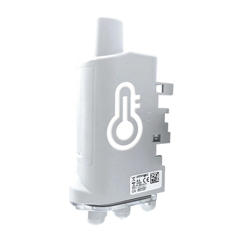
IME
IME ADEUNIS TEMP V4 IP68 Sigfox RC1 User manual
IME
IME Nemo 96 HDLe User manual
IME
IME Nemo 96HDL User manual
IME
IME Nemo 96HD User manual
IME
IME Nemo 72 Le User manual

IME
IME Conto D4-Pt MID User manual
IME
IME CE4DMID31 Quick start guide
IME
IME CONTO D6 User manual

IME
IME CONTO D6 User manual

