10785103
Cod. MF96421SR
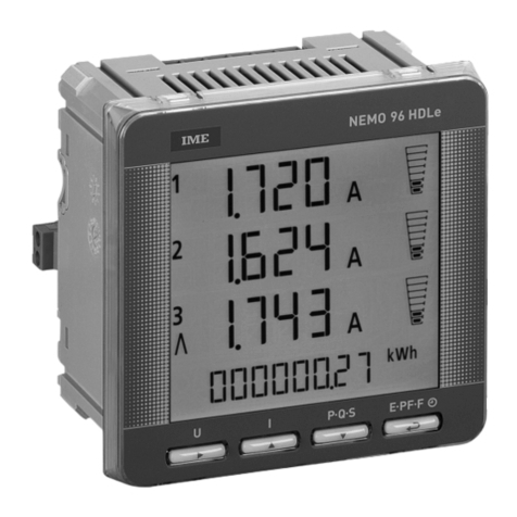
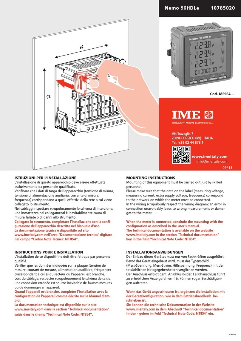
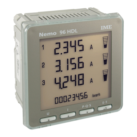
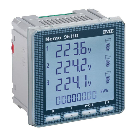
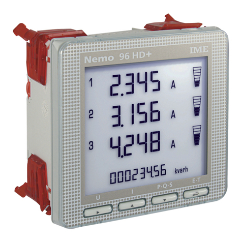
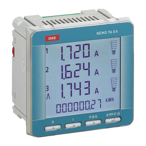
Nemo 96HDLe 10785103
Rogowski
ATTENZIONE!
Prima di installare il sensore di Rogowski attorno ad un conduttore non isolato
verificare che il conduttore non sia sotto tensione. In caso contrario togliere
alimentazione al circuito prima di procedere all’installazione del sensore.
Il sensore di Rogowski non deve avvolgere il conduttore su cui è installato
stringendolo. Nella scelta del sensore accertarsi che il diametro interno del
sensore sia sempre maggiore di quello del conduttore su cui è installato.
Verificare attentamente la chiusura del connettore a baionetta.
Se il sensore non è chiuso perfettamente o è lasciato aperto lo strumento
multifunzione abbinato visualizzerà misure falsate.
INSTALLAZIONE
1Aprire il connettore a baionetta (F.1)
2Avvolgere il sensore attorno al conduttore (F.2) rispettando il senso della
corrente indicato dalla freccia posta sul sensore (F.3)
3Chiudere il connettore a baionetta (F.4)
ATTENTION!
Before mounting the Rogowski coil around a non-insulated cable please verify that the cable is not under voltage. In the negative
please turn off supply voltage before mounting the coil.
Rogowski coil must not wrap and tighten the cable on which it is mounted. In choosing the coil verify that its inner diameter is
always bigger than the cable on which it is mounted. Attention: please carefully verify closing of the bayonet connector.
If the coil is not perfectly closed or left open the connected multifunction meter will display wrong measurements.
MOUNTING
1Open the bayonet connector (F.1)
2Wrap the coil around the cable (F.2) respecting the current sense shown by the arrow on the coil (F.3)
3Close the bayonet connector (F.4)
ATTENTION!
Avant de monter le capteur à bobine de Rogowski autour de un conducteur pas isolé vérifier qu’il ne soit pas sous tension.
Dans le cas contraire il faut enlever l’alimentation au circuit avant de monter le capteur à bobine.
Le capteur à bobine de Rogowski ne doit pas envelopper et serrer le conducteur où il est monté.
En choisissant le capteur à bobine s’assurer que son diamètre intérieur soit toujours plus grand que le conducteur où il est monté.
Attention: prions vérifier attentivement la fermeture du connecteur à baïonnette. Si le capteur à bobine n’est pas parfaitement
fermé ou bien laissé ouvert l’appareil multifonction branché affichera des mesures faussées.
INSTALLATION
1Ouvrir le connecteur à baïonnette (F.1)
2Envelopper le capteur à bobine autour du conducteur (F.2) en respectant le sense du courant indiqué par la flèche sur le
capteur à bobine (F.3)
3Fermer le connecteur à baïonnette (F.4)
ACHTUNG!
Vor der Rogowskispule um einen unisolierten Stromleiter zu montieren bitte kontrollieren dass der Stromleiter nicht unter
Spannung ist. Andernfalls den Strom vor der Montierung der Spule abschalten.
Die Rogowskispule muss nicht einwickeln und drücken den Stromleiter auf den montiert ist.
Wenn Sie die Spule wählen bitte kontrollieren dass den Innendurchmesser der Spule immer größer als den Stromleiter ist.
Achtung: bitte aufmerksam kontrollieren den Bajonettsteckerverschluß. Wenn die Spule nicht perfekt geschlossen oder offengelas-
sen ist wird das angeschlossene Multifunktionsgerät falsche Messungen anzeigen.
MONTIERUNG
1Öffnen den Bajonettstecker (F.1)
2Die Spule um den Stromleiter einwickeln (F.2) In diesem Fall sollen Sie die Stromrichtung die von dem Pfeil auf der Spule
gezeigt ist folgen (F.3)
3Schliessen den Bajonettstecker (F.4)
F.3
F.2
F.2
Load
F.4 F.1
Load
ISTRUZIONI PER L’INSTALLAZIONE
Questo prodotto deve essere installato in conformità con le regole d’installazione
e di preferenza da un elettricista qualificato. L’eventuale installazione impropria
e/o utilizzo improprio dello stesso possono comportare rischi di shock elettrico o
incendio. Prima di procedere all’installazione leggere attentamente le istruzioni e
individuare un luogo di montaggio idoneo in funzione del prodotto.
Non aprire smontare alterare o modificare l’apparecchio eccetto speciale
menzione indicata nel manuale. Tutti i prodotti IME devono essere esclusivamente
aperti e riparati da personale adeguatamente formato e autorizzato da IME.
Qualsivoglia apertura o riparazione non autorizzata comporta l’esclusione di
eventuali responsabilità diritti alla sostituzione e garanzie.
Verificare che i dati di targa dell’apparecchio (tensione di misura tensione di alimenta-
zione ausiliaria corrente di misura frequenza) corrispondano a quelli effettivi della rete
a cui viene collegato lo strumento.
Nei cablaggi rispettare scrupolosamente lo schema di inserzione; una inesattezza
nei collegamenti è inevitabilmente causa di misure falsate o di danni allo strumento.
Collegato lo strumento, completare l’installazione con la configurazione dell’apparecchio
descritta nel Manuale d’uso.
La documentazione tecnica è disponibile sul sito www.imeitaly.com nell’area “Documentazione
tecnica” digitare nel campo “Codice Nota Tecnica:
NT890”.
INSTRUCTIONS POUR L’INSTALLATION
Ce produit doit être monté conformément aux normes de installation et de préfé-
rence par un électricien qualifié. Une éventuelle installation et/ou usage impropre
de l’appareil peuvent comporter risques de choc électrique ou incendie.
Avant de monter l’appareil lire attentivement les instructions et repérer un lieu de
montage apte a sa fonction.
Ne pas ouvrir démonter altérer ou modifier l’appareil sauf pour la mention spé-
ciale indiquée sur le catalogue. Tous les produits IME doivent être ouverts et réparés
seulement par personnel formé d’une manière adéquate et autorisé par IME.
Chaque ouverture ou réparation pas autorisée comporte l’exclusion d’éventuelles
responsabilités droits à la substitution et garanties.
Vérifier que les données indiquées sur la plaque (tension de mesure tension d’alimenta-
tion auxiliaire courant de mesure fréquence) correspondent à celles du secteur ou
l’appareil est branché.
Lors du câblage respecter scrupuleusement le schéma de saisie; une connexion
erronée est source inévitable de fausses mesures ou de dommage à l’appareil.
Quand l'appareil est branché, compléter l'installation avec la configuration de l'appareil comme
décrite sur le Manuel d'emploi.
La documentation technique est disponible sur le site www.imeitaly.com dans la section
"Technical documentation" saisir dans le champ “Technical Note Code:
NT890
”.
MOUNTING INSTRUCTIONS
This product must be mounted according to the mounting rules and preferably by
a skilled electrician. Possible wrong mounting and/or misuses of the device may
involve the risk of electric shock or fire.
Before mounting please carefully read the instructions and find a mounting place
which fits its functions.
Do not open dismantle tamper or modify this device except for the special
mention reported in the manual. All the IME’s products must be opened and
repaired only by personnel properly trained and authorized by IME.
Any unauthorized opening or repair leads to the exclusion of every responsibility
rights to replacement and guarantees.
Please make sure that the data on the label (measuring voltage extra supply voltage
measuring current frequency) correspond to the network on which the meter must be
connected.
In the wiring scrupulously respect the wiring diagram; an error in connection
unavoidably leads to wrong measurements or damages to the device.
When the meter is connected, conclude the mounting with the configuration as described in the
user's manual.
The technical documentation is available on the website www.imeitaly.com in the section
"Technical documentation" key in the field “Technical Note Code:
NT890
”.
INSTALLATIONSANWEISUNGEN
Dieses Produkt soll nach den Installationsregeln und vorzugsweise von einem
Fachelektriker montiert werden. Eine falsche Montierung und/oder Verwendung
dieses Produktes kann mit Gefahren von elektrischen Schlag oder Feuer verbunden
ist. Vor den Montierung sollen Sie aufmerksam die Anweisungen lesen und eine
geeignete Montierungsplatz für das Gerät finden.
Sie sollen nie dieses Gerät öffnen verändern oder modifizieren außer die spezielle
Erwähnung die auf dem Handbuch gezeigt ist.
Die volle Produktsreihe I.M.E. kann nur von ausgebilten Personal geöffnet und
repariert werden und von I.M.E. ermächtigt. Jede nicht autorisierte Öffnung oder
Reparatur führt zum Ausschluß von eventuellen Haftungen Auswechslungsrechte
und Garantien.
Bevor das Gerät eingebaut wird muss das Typenschild (Mess-Spannung Mess-Strom
Hilfsspannung Frequenz) mit den tatsächlichen Netzgegebenheiten verglichen wer-
den. Der Anschluss erfolgt gem. Anschlussbilder. Falschanschluss führt zu erhebli-
chen Anzeigefehlern! Es können sogar Beschädigungen auftreten.
Wenn das Gerät angeschlossen ist, ergänzen die Installation mit der Gerätskonfiguration, wie in
dem Betriebshandbuch beschrieben ist. Sie konnen die technische Dokumentation in der Web-
site www.imeitaly.com in dem Abschnitt "Technical documentation" finden - geben im Feld
“Technical Note Code:
NT890
” ein.
Via Travaglia 7
20094 CORSICO (MI) ITALIA
Tel. +39 02 44 878.1
www.imeitaly.com
info@imeitaly.com
01/ 18


