Inspur Yingxin User manual

Dear users of Inspur Yingxin server:
Sincerely thank you for selection of Inspur Yingxin server!
This manual introduces the technical characteristics and the system installation and setup of
the server, and helps you to particularly understand and expediently use this server.
Please deliver the package of our product to the waste recycling station for recycling, in favor
of pollution prevention and humankind benefit.
This manual is the property of the Inspur Group Co., Ltd.
This User Manual is not to be copied by any group or person in any manner without the
consent of Inspur Group Co., Ltd. The Inspur Group Co., Ltd. reserves the right of revising this
manual momentarily.
Any alteration about the content of this manual will not be noticed.
Please contact Inspur, if you have any questions or advice about this manual.
Inspur
October 2013
“Inspur” and “Yingxin” are registered trademarks of Inspur Group Co., Ltd.
Other trademarks belong to other corresponding registered companies.

Statement
Please read the following statement before you use Inspur Yingxin server formally. Only
when you have read this statement hereinafter and agreed the following terms, you can formally
use Inspur Yingxin server. If you have any questions about the following terms, please contact our
supplier or us directly. If you have no questions about these terms and start to use this server, it
acquiesces that you have agreed the following terms.
1. We must call your attention that you must not alter any other parameters in the main board
BIOS or SATA controller BIOS of Inspur Yingxin server at any time, except for the parameters
which we prompt that you can alter.
2. If there are any hardware problems when you use this server, or you wish to upgrade the
hardware, please feed back the detailed hardware configuration of your computer to our Customer
Service Center. Don’t disassemble the server case or any hardware components in the case by
yourself.
3. In Inspur Yingxin server, the MEMORY, CPU, CPU Fan and Fan are in given standard. Please
don’t use them with the corresponding components of any other computers confusedly.
4. When you have any software problems during the application of this server, we hope that you
firstly contact the corresponding software supplier and then he will contact us in favor of
communication so as to solve your problem together, especially the software problems about the
database, the installation and running of the network management software or other networking
product.
5. Please firstly read the accompany Brief User Guide before you use Inspur Yingxin server.
6. We must call your attention that in the application process, you should pay attention to do
necessary backup of your file.
7. This is a Grade A product, and this product may induce radio jamming. In this case, users need
to adopt feasible measures to the interference.
8. When this product is at the end of its service life, please do not mix it with other wastes to
dispose. The user should get the related disposal method and location from the retailers or the
local government department in order to do the safe and environmental cyclic utilization and
benefit humankind.
9. The copyrights of the markers and names of the software and hardware product referred in this
manual are the property of corresponding companies.
10. In the above statement, “us” indicates Inspur. Inspur holds the right of final explanation about
the above statement.

Regarding the Manual
●Product Description
In this chapter, the technical characteristics, appearance characteristics and I/O interface
technical specifications of this server are introduced.
●System Setup
In this chapter, the setup of jumper wire and the system BIOS of this server is introduced.
●SATA RAID Setup
In this chapter, how to set up the onboard SATA RAID is introduced.
●Operating System Installation
In this chapter, how to install the prevailing operating systems to the server is introduced.
●Common Problems and Trouble-shooting
In this chapter, solutions of some common problems are introduced.
We suggest you read this manual seriously before you use this server for sake of the
unnecessary faults in your operation.
Address: No.1036 Langchao Road, Jinan City, China
Postcode: 250101

Safety Information
Warning: the following warnings show that there are potential dangers that may
cause property loss, personal injury or death:
Warning 1: The power supply equipment in the system may generate high voltage and
dangerous electrical energy and thus cause personal injury. Please do not dismount the cover
of the host or to dismount and replace any component in the system by yourself, unless
otherwise informed by Inspur; only maintenance technicians trained by Inspur have the
right to disassemble the cover of the host, dismount and replace the internal components.
Warning 2: Please connect the equipment to appropriate power supply, and the power
should be supplied by external power supply which is indicated on the rated input label. To
prevent your equipment from damages caused by momentary spike or plunge of the voltage,
please use relevant voltage stabilizing equipment or uninterruptible power supply
equipment.
Warning 3: If extended cables are needed, please use the three-core cables matched
with correct earthed plug, and check the ratings of the extended cables to make sure that the
sum of rated current of all products inserted into the extended cables do not exceed 80% of
the limits of the rated currents of the extended cables.
Warning 4: Please be sure to use the supplied power supply component, such as power
lines, power socket (if supplied with the equipment) etc.. For the safety of equipment and the
user, do not replace randomly power cables or plugs.
Warning 5: To prevent electric shock dangers caused by leakage in the system, please
make sure that the power cables of the system and peripheral equipment are correctly
connected to the earthed power socket. Please connect the three-core power line plug to the
three-core AC power socket that is well earthed and easy to access, be sure to use the
earthing pin of power lines and do not use the patch plug or the earthing pin unplugged with
cables. In case of the earthing conductors not installed and it is uncertain whether there are
appropriate earthing protections, please do not operate or use the equipment. Contact and
consult with the electrician, please.
Warning 6: To avoid short circuit of internal components and fire or electric shock
hazards, please do not fill any object into the open pores of the system.
Warning 7: Please place the system far away from the cooling plate and at the place
with heat sources, and be sure not to block the air vents.
Warning 8: Be sure not to scatter food or liquid in the system or on other components,
and do not use the product in humid and dusty environment.
Warning 9: The replacement of batteries with those of another model may cause
explosion. When replacement of batteries is required, please consult first the manufacturer
and choose batteries of the same or a similar model recommended by the manufacturer. Do

not dismount, extrude and pink the batteries or make the external connection point short
circuit, and do not expose them in the environment over 60°C. Never throw them into fire or
water. Please do not try to open or repair the batteries, and be sure to reasonably deal with
the flat batteries and do not put the flat batteries, the circuit boards that may include the
batteries and other components with other wastes. For relevant battery recovery, please
contact the local waste recovery and treatment mechanism.
If what you bought is the chassis, besides carefully read the installation description
attached with the cabinet products and get known about the special warning notices and
installation process, you must abide by the following preventive measures to guarantee the
cabinet to be stable and safe:
Warning 10: Before installing equipment in the chassis, please install front and side
supporting feet on the independent chassis; for cabinet connecting with other chassis, it shall
install the front supporting foot first. If you fail to install correspondingly the supporting
foot before installing equipment in the chassis, it may cause the cabinet to turn over in some
cases, and thus may cause personal injury. Therefore, it is necessary to install supporting
feet before installing equipment in the chassis. After installing the equipment and other
components in the chassis, it can only pull out one component from the cabinet through its
sliding component at one time. Pulling out several components at the same time may lead the
cabinet to turn over and cause serious personal injury.
Warning 11: Please do not move the chassis. Considering the height and weight of the
chassis, at least two people are needed to complete its movement.
Warning 12: Declaration
The product is Grade A product, and in the living environment, it may cause radio
interference. In such case, it may need the user to take feasible measures for the interference.
Notes: in order to help you use the equipment, the following considerations can help avoid the
occurrence of problems that may damage the components or cause data loss:
1. In case of the following cases, please unplug the power line plug of products from the
power socket and contact the customer service department of Inspur:
- The power cables, extended cables or power plugs are damaged.
- The products get wet by water.
- The products have fallen off or been damaged.
- Objects fall into the products.
- When operating according to the operation instructions, the products cannot function
normally.
2. If the system becomes damp, please treat it according to the following steps:
- Switch off the power supplies of the system and the equipment, disconnect them with the

power socket, wait for 10 to 20 minutes, and then open the cover of the host.
- Move the equipment to the ventilation place to dry the system at least for 24 hours and
make sure that the system is fully dried.
- Close the cover of the host, re-connect the system to the power socket, and then start the
equipment.
- In case of operation failure or abnormal situation, please contact Inspur and get technical
support.
3. Pay attention to the position of the system cables and power cables, wire them in places
not to be stepped on or knocked down and ensure not to place other objectives on the cables.
4. Before dismounting the cover of host or contacting the internal components, you shall cool
down the equipment first; to avoid damaging the main-board, please power off the system and
wait for 5 seconds, and then dismount the components from the main-board or disconnect the
connection of peripheral equipment of the system.
5. If there are modulator-demodulator, telecommunication or local area network options in
the equipment, please pay attention to the following matters:
- In case of thunder and lightning weather, please do not connect or use the
modulator-demodulator. Otherwise, it may be subject to lightning strike.
- Never connect or use modulator-demodulator in moist environment.
- Never insert the modulator-demodulator or telephone cables to the socket of network
interface controller (NIC).
- Before unpacking the product package, contacting or installing internal components or
contacting un-insulated cables or jacks of the modulator-demodulator, please disconnect the
modulator-demodulator cables.
6. In order to prevent the electrostatic discharge from damaging the electronic components in
the equipment, please pay attention to the following matters:
- You shall conduct off the static electricity on the body before dismounting or contacting any
electronic component in the equipment. You can conduct off the static electricity on the body by
contacting the metal earthing objects (such as the unpainted metal surface on the chassis) to
prevent the static electricity on the body from conducting itself to the sensitive components.
- For electrostatic sensitive components not ready to be installed for application, please do

not take them out from the antistatic package materials.
- During the work, please touch the earthing conductor or the unpainted metal surface on the
cabinet regularly to conduct off the static electricity on the body that may damage the internal
components.
7. When dismounting the internal components with the approval of Inspur, please pay
attention to the following matters:
- Switch off the system power supply and disconnect the cables, including disconnecting any
connection of the system. When disconnecting the cables, please grab the connector of cables and
plug it out, and never pull the cables.
- Before dismounting the cover of cabinet or touching the internal components, the products
need to be cooled down.
- Before dismounting and touching any electronic component in the equipment, you shall
conduct off the static electricity on the body by touching the metal earthing objectives.
- During the dismounting process, the operation shall not be too big, so as to prevent damage
to the components or scratching of the arms.
- Carefully deal with the components and plug-in cards, and please never touch the
components or connection points on the plug-in cards. When taking the plug-in cards or
components, you should grab the edges of the plug-in cards or components or their metal fixed
supports.
8. During the process of cabinet installation and application, please pay attention to the
following matters:
- After the installation of cabinet is finished, please ensure that the supporting feet have been
fixed to the rack and supported to the ground, and all weight of the rack have been fell onto the
ground.
- It shall install into the cabinet according to the sequences from the bottom to the top, and
first install the heaviest component.
- When pulling out the components from the cabinet, it shall apply force slightly to ensure the
cabinet to keep balance and stabilization.
- When pressing down the release latch of the sliding rail of components and sliding in or out,
please be careful, as the sliding rail may hurt your figures.
- Never make the AC power branch circuit in the cabinet overload. The sum of cabinet load
shall not exceed 80% of the ratings of branch circuits.
- Ensure that components in the cabinet have good ventilation.
- When repairing components in the cabinet, never step on any other components.

Contents
STATEMENT........................................................................................................................................II
REGARDING THE MANUAL………………………………………………………………………III
SAFETY INFORMATION..................................................................................................................IV
CHAPTER ONE PRODUCT DESCRIPTION....................................................................................1
1.1 Server Technical Specification............................................................................................1
1.2 Front Panel View.................................................................................................................2
1.3 Back Panel Introduction......................................................................................................4
CHAPTER TWO SYSTEM SETUP.....................................................................................................6
2.1 Motherboard BIOS Setup....................................................................................................6
2.2 Motherboard Jumper Settings...........................................................................................12
CHAPTER THREE SETUP OF SAS RAID......................................................................................14
3.1 How to Enter the Configuration Interface of SATAHostRaid..........................................14
3.2 Control KeyApplication...................................................................................................14
3.3 SATA HostRaid Configuration..........................................................................................15
CHAPTER FOUR OPERATING SYSTEM INSTALLATION ......................................................17
4.1 Manually Install Windows Server 2008 R2......................................................................18
4.2 Manually Install Red Hat Enterprise Linux 6.2................................................................21
CHAPTER FIVE COMMON PROBLEMS AND TROUBLE-SHOOTING .................................25
5.1 Restarting the Server.........................................................................................................25
5.2 Problems When Starting the Machine...............................................................................25
5.3 Machine Alarm..................................................................................................................28
5.4 Additional Notes ...............................................................................................................28
5.5 Technical Support Information..........................................................................................29

Chapter One Product Description
1.1 Server Technical Specifications
Processor
Processor Type
Intel Xeon E3-1200 serious CPU
Processor Count
1
Processor
Technology
32nm
Processor
Interface
LGA1150 Sockets
Chipset
Chipset Type
Intel C222 chipset
Memory
Memory Type
DDR3 1066MHz/1333MHz ECC Unbuffered memory
DIMM
4
Memory
Capacity per slot
2GB, 8GB
Total Memory
Up to 32GB
I/O Interface
Keyboard and
Mouse
Interface
1 PS/2 keyboard & mouse interface
USB Interface
7 USB interfaces (2 rear USB 3.0 interfaces, 2 rear USB 2.0 interface, 2 front
USB 2.0 interfaces, 1 built-in USB interface)
Serial Interface
1 rear serial interface
Network
Interfaces
2 RJ45 network interfaces
Display Interface
1 rear VGA interface
Display Controller
Controller Type
Onboard Aspeed AST1100 display controller
Video Memory
64MB video memory
HDD Controller
SATA Controller
Intel C222 chip integrated SATA controller, 2 SATA interfaces of 6Gb/s and
4 SATA interfaces of 3Gb/s on the motherboard, support RAID0,RAID1,
RAID10,RAID5 (only support Windows XP and above Windows operating
system)
Network Card
Network Card
Controller
Onboard Intel I210AT Gigabit network controller chip, 2 network interfaces

PCI Expansion Slot
PCI Bus Type
PCI and PCI-E
PCI Slot
3 PCI 32bit/33MHz 5V slots
PCI-E Slot
1 PCI-E x8 slot
1 PCI-E x16 slot
Hard Disk
Hard Disk Type
3.5″SATA hard disk
Hard Disk
Number
Standard configuration supports 4 pieces of SATA hard disks or up to 8 pieces
of SATA hard disks through expansion accessories
External Storage Drive
Inspur driver U
disk
Optional Inspur Driver U disk, used to load hard disk controller driver when
installing the operating system manually
CD-ROM
(optional)
Optional SATA standard CD-ROM
Power Supply and Consumption
Power
>=300wAC power supply
Physical Specification
External Size of
Package
W (width) 600mm; H (height) 465mm; D (depth) 673mm
Whole Chassis
Size
W (width) 200mm; H (height) 433mm; D (depth) 492mm
Weight
Standard configuration: net weight 13.5kg, gross weight 21.5kg;
Full configuration: net weight 15.5kg, gross weight 23.5kg
Environment Parameters
Operating
Environment
Temperature
10℃-35℃
Storage &
Transportation
Temperature
-40℃-55℃
Operating
Humidity
35%-80%(relative humidity)
Storage &
Transportation
Humidity
20%-93%(40℃) (relative humidity)
1.2 Front Panel View

Front Panel View
Number
Name
Function and Introduction
1
Power button
Server on/off button
2
Reset button
System reset button
3
Power indicator
Always on when server works
4
Hard disk LED
indicator
Display hard disk working condition, blinks when
hard disk is reading and writing
5
Network card 1st
indicator light
Always on: network is connected
Blinking: data are being transmitted
6
Network card 2nd
indicator light
Off: network is not connected
7
Front USB interface
1/2
Connect the USB devices
8
CD-ROM(Optional)
SATA standard CD-ROM
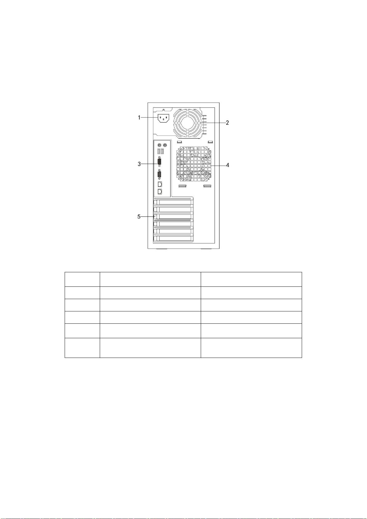
1.3 Back Panel Introduction
1.3.1 Back Panel View
Back Panel View
Number
Name
Function and Introduction
1
Power interface
Connect the host power line
2
Power fan
Power cooling fan
3
I/O interface
Input/output interface
4
Chassis fan
System cooling fan
5
PCI and PCI-E expansion slot
Expansion devices connecting PCI
and PCI-E interfaces

1.3.2 I/O Interface
I/O Interface View
Number
Name
Function and specification
1
PS/2 mouse &
keyboard interface
For connecting PS/2 mouse
2
Rear USB 2.0
interfaces 1, 2
For connecting USB 2.0 interface devices
3
Rear USB 3.0
interfaces 1, 2
For connecting USB 3.0 interface devices
4
Serial interface
For connecting serial interface devices
5
VGA interface
For connecting display devices
6
Integrated network
card interface 1
Onboard gigabit network card interface 1
7
Integrated network
card interface 2
Onboard gigabit network card interface 2
8
Network connecting
indicator light
Off: network is not connected
Green light always on: network is connected
Green light blinking: data are being transmitted
through network
9
Network working
indicator light
Off: network transmission rate is 10Mb/s
Orange light on: network transmission rate is
100Mb/s

Green light on: network transmission rate is
1Gb/s
Chapter Two System Setup
In this chapter, the jumper of motherboard and BIOS function setup of this server are
introduced. Only operator or administrator with qualification of system maintenance can
implement these operations described in this part.
2.1 Motherboard BIOS Setup
BIOS is a basic input and output system. With some special setting programs, it can adjust
the system parameter and the hard disk parameter. As BIOS has great influence on the starting and
running of the system, setting parameters improperly may arise the conflict among hardware
resources, or affect the system’s performance. Hence understanding the BIOS setup is significant
to the configuration of your server. If there is no special requirement, we suggest you use the
default value and not alter the parameters.
Notes:
1.Before the server BIOS setup is altered, please record the corresponding original setup.
Hence when there are operating problems in the system due to the alteration, the setup can be
reversed.
2.The factory default system setup is usually the optimized setup. Don’t try to alter the
parameters before you understand their denotations.
3.The common setup is introduced in detail in this chapter. For items less used in the
application, this chapter only offers simple instruction or just omits the instruction.
4.The contents of the BIOS may differ due to the different configurations of products; no
detailed introduction will be provided here.
How to Enter the BIOS Setup
Power up and start the server. When the prompt of “Press DEL to run Setup. Press Tab to
display BIOS POST Message. Press Alt+F2 to run EzFlash”is displayed at the bottom of the
screen, press [DEL] and then the system enters BIOS setup.
If the system does not enter BIOS setup after previous steps, please press [Ctrl]-[Alt]-[Del] at
the same time to reset the system, and repeat operations above. (If the prompt displays to press
[DEL] again, please press it quickly.)
BIOS System Menu Introduction
Next the following main function menus of BIOS are introduced.
Menu Name
Menu Function

Main
Configuring the basic system settings, such as system time,
system date, super user and user password setup;
displaying version of BIOS, CPU, and memory
information, etc.
Event Logs
Configuring system event log setup
Advanced
Configuring advanced characteristics of chipset
Monitor
Displaying system temperature, power supply state and fan
setup
Boot
Configuring boot priority of system devices
Security
Configuring security setup of system
Tool
Configuring system special function option setup
Exit
Saving or exiting BIOS setup, etc
There are some items that cannot be set in BIOS, for example some information on system’s
automatic detection and configuration. A right-pointing signal may be found before some items,
which means if this item is selected, and press [Enter] , the system will enter the cascading menus
(i.e. submenus).
Introduction of operational keys:
Button
Description
↑(up)
For selecting the upper menu or value
↓(down)
For selecting the next menu or value
←(left)
For selecting the left menu or value
→(right)
For selecting the right menuor value
Esc
For returning to the superior menu or the main menu
+
For changing the item value
For changing the current menu item into the
previous item value
The key only displays the item values relevant to the
item itself rather than all the item values
—
For changing the item value
For changing the current menu item into the next
item value
The key only displays the item values relevant to the
item itself rather than all the item values
F1
The help key for displaying the relevant introduction
of current menu
F5
For restoring to the default setting of the system
optimum performance

F10
For saving CMOS settings and exiting
Enter
For executing current command or entering the
submenu
1. Main menu
Entering BIOS setup utility, you can see Main menu displayed firstly. Use the arrow key to
select the option, and press [Enter] to select submenu.
●BIOS Information
Display BIOS’s manufacturer information.
●BIOS Version
Display BIOS version.
●Build Date
Display BIOS build date.
● System Date
Set the system date, in format of [week month/day/year].
● System Time
Set the system time, adopting 24 hour system, in format of [hour/minute/second] .
2. Event logs menu
●Change Smbios Event Log Settings
This menu is used to set the system management BIOS event log option.
* Smbios Event Log
This option is used to set all the characteristics of the system management BIOS event logs
when open or close system startup. There are [Disabled] and [Enabled] two options.
* Erase Event Log
This option is used to set whether clear event logs or not, there are [No], [Yes, Next reset]
and [Yes, Every reset] three options.
* When Log is Full
This option is used to set the approach when event logs are full, there are [Do nothing] and
[Erase Immediately] two options.
●View Smbios Event Log
Press [Enter] to enter this menu, you can check system management BIOS event log.
3. Advanced menu
Advanced menu includes the following submenus or setting items.

ACPI Settings
Trusted Computing
WHEA Configuration
CPU Configuration
North Bridge
South Bridge
SATA Configuration
Intel TXT(LT) Configuration
USB Configuration
Onboard Devices Configuration
APM
Serial Port Console Redirection
● CPU Configuration
Select this item, and press [Enter] to enter the menu.All the items or submenus in this menu
are used to check and set the related information and parameter about the CPU. Select the default
value.
* Hyper-threading
CPU hyper-threading function setup includes [Enabled] and [Disabled] two items.
* Intel Virtualization Technology
CPU virtualization technology support function setup, including [Enabled] and [Disabled]
two items. If you want to modify this item, you need to power off the machine and reboot, then the
setup can take effect.
● PCH-IO Configuration
Press [Enter] to enter this menu.All the items or submenus in this menu are used to check
and set the related information and parameter about the PCH. Select the default value.
* USB Configuration
USB function configuration.
* PCH Azalia Configuration
Azalia test function configuration.
●SATA Configuration
Press [Enter] to enter this item to set the IDE device model installed to the system.
* SATA Mode
This item is used to set SATA model including [Disabled], [IDE Mode], [AHCI Mode] and
[RAID Mode] four items.
If you want to use serial devices as parallel IDE storage devices when onboard SATA
controller is used, please set this item to [IDE Mode].
If you do not use RAID and want to connect 1-6 SATA devices when onboard SATA
controller is used, please set this item to [AHCI Mode].
If you want to use RAID when onboard SATA controller is used, please set this item to
[RAID Mode] (only Windows system is supported at this time).
* Serial-ATA Controller 0
This item only appears when SATA Mode option is set to [IDE Mode].
* Serial-ATA Controller 1

This item only appears when SATA Mode option is set to [IDE Mode].
● Systems Agent(SA)Configuration
Press [Enter] to enter this item to set the configuration of system agent parameter.
* VD-T
This item is used to set whether to enable Intel virtualization technology, having [Disabled]
and [Enabled] two options.
* Memory Configuration
This item is used to change the settings of memory information.
●PCI Subsystem Settings
Press [Enter] to enter this item to set the configuration of PCI subsystem.
*Above 4G Decoding
This item is used to set whether to enable devices with 64-bit computing power to decode the
above 4G address space, having [Disabled] and [Enabled] two options.
* PCI Express Setting
This item is used to change the settings of memory PCI Express device.
-ASPM Support
This item is used to enable or disable the support for ASPM function. Using ASPM power
management protocol can maximize battery life, having [Disabled]、[Auto]and[Force L0s]three
options. Selecting [Disabled] can forbid ASPM function, selecting [Auto] can use BIOS automatic
configurationASPM function, and selecting [Force Los] can force all links to LOs state.
* PCI Slot Configuration
This item is used to configure the performance of PCIE slot.
-PCIE Option Rom 4-5
This item is used to enable or disable PCIE slot function.
●USB Configuration
Press [Enter] to enter this item to set some configuration related to USB devices.
* Legacy USB Support
This item is used to set whether to enable or disable the legacy USB support, having [Auto],
[Disabled] and [Enabled] three options. It set to [Auto], system will detect whether there is USB
device during startup, if there is, the downward compatibility mode of USB controller will be
opened, if there isn’t, the downward compatibility mode of USB controller will be closed.
* USB 3.0 Support
This item is used to enable or disable USB3.0 controller support, having [Disabled] and
[Enabled] two options.
*USB Mass Storage Driver Support
This item is used to enable or disable the support for USB mass storage drive, [Disabled] and
[Enabled] two options.
* Port 60/64 Emulation

This item is used to configure I/O port 60h/64h simulation support. In non-USB recognition
operating system, this item must be enabled to fully support old-fashioned USB keyboard, having
[Disabled] and [Enabled] two options.
●ACPI
Press [Enter] to enter this item to set the configuration of ACPI.
* Enable Hibernation
This item is used to set whether to enable or disable hibernation function (OS/S4 in sleep
state), having [Disabled] and [Enabled] two options.
*ACPI Sleep State
This item is used to set ACPI sleep state, having [Suspend Disabled],[S1 only],[S3 only]
and [Both S1 and S3] four options.
● Onboard LAN Configuration
This menu is used to set onboard network configuration.
● APM
This menu is used to set APM configuration.
Advanced power management configuration
* Restore on AC Power Loss
It is the power condition configuration after the system powers down. [Power Off] is
shutdown state which needs to power on manually; [Last state] is the state when it powers down
last time; [Power on] is the automatic startup state.
4. Boot menu
Boot menu is mainly used to the configuration of system boot devices priority.
● Setup Prompt Timeout
This item is used to configure the time before entering Setup. Using <+> and <-> in the
keyboard to set the time to activate.
● Bootup NumLock State
This item is used to configure the on and off state of the NumLock, and the default is
[Enabled], having [Disabled] and [Enabled] two options.
● Full Screen Logo
This item is used to configure whether display Logo picture on full screen, and the default is
[Disabled], having [Disabled] and [Enabled] two options.
● Boot Device Seeking
Set whether to search for remote boot screen during startup, having [Endless PXE] and
[Normal] two options. Selecting [Endless PXE], system will keep searching for remote boot
screen until it is found or being terminated by user. Selecting [Normal], system will search for
remote boot screen only once, if not found, system will boot locally.
● Boot Option #x
This item is used to configure the boot devices corresponding to boot priority. Select one boot
priority and press [Enter], then select the boot device in the pop-out list to finish the configuration.
● Network Device BBS Priorities/Hard Drive BBS Priorities
This item is used to set the boot priorities of network devices.
● CSM Parameters

This item is mainly used to set the configuration of OpRom.
5. Monitor menu
This menu is used to display system temperature (such as CPU temperature, motherboard
temperature), power supply working state, speed of CPU fans and other fans as well as configure
the fan speed control mode.
●FAN Speed Control
The configuration of fan speed control mode includes [Full Speed Mode], [High Density
Mode], [Generic Mode] and [Whisper Mode] four items. This item involves the system cooling
guarantee, we do not suggest you to modify the parameter by yourselves.
6.Security 菜单
System security setup, entering this item can set system superuser and user password.
●Administrator Password
This item is used to set or change super user password.
If you forget superuser password, you can clear superuser password through clearing CMOS.
●User Password
This item is used to set or change user password.
●Secure Boot Menu
Enable or disable the secure boot process control.
7.Tool 菜单
Tool menu is mainly used to set special functions.
● Start EzFlash
This menu can be used to update BIOS.
8. Exit menu
The options in Exit menu can be used to save or discard the settings of the changes in the
BIOS and exit the setting program.
●Save Changes and Exit
Select this item and press [Enter]. After you select <Yes> for confirmation, the changes in
the BIOS settings will be saved and the system will exit the BIOS setup. The menu modification
function can use [F10] shortcut key to realize.
●Discard Changes and Exit
Select this item and press [Enter]. After you select <Yes> for confirmation, the changes in the
BIOS settings will be discarded and the system will exit the BIOS setup.
2.2 Motherboard Jumper Settings
Open the Chassis Side Panel
If the user need alter motherboard jumpers, please first obtain the authorization of Inspur.
Then open the chassis upper panel according to the following steps:
1. Power off the system (disconnect AC power cable).
Other manuals for Yingxin
3
Table of contents
Other Inspur Server manuals

Inspur
Inspur NF5280M5 User manual

Inspur
Inspur Yingxin NF5280M2 User manual

Inspur
Inspur Yingxin NP3020M2 User manual

Inspur
Inspur NF3180A6 User manual

Inspur
Inspur NF8480M5 Instruction Manual

Inspur
Inspur NF5220 User manual

Inspur
Inspur NF5270M3 User manual

Inspur
Inspur NF3120M5 User manual

Inspur
Inspur ON5263M5 User manual

Inspur
Inspur NF5260FM6 User manual

Inspur
Inspur NX5460M4 User manual

Inspur
Inspur Yingxin NX5440M4 User manual

Inspur
Inspur NP3060 User manual

Inspur
Inspur NF5180M6 User manual

Inspur
Inspur NF5266M6 User manual

Inspur
Inspur I48 User manual

Inspur
Inspur NF5486M5 User manual

Inspur
Inspur NF5280M6 User manual

Inspur
Inspur NF8380M5 User manual

Inspur
Inspur i24 User manual


