iPA SUPER RANGER MUTT User manual

Innovative Products of America®Incorporated
888-786-7899 • 234 Tinker Street, Woodstock, NY 12498 • www.ipatools.com
Ultra Portable, Battery Powered, Advanced
Diagnostic Trailer ABS and Light Tester
MADE IN
USA
OPERATOR’S MANUAL
#4300A-L4
SUPER RANGER MUTT®
Mobile Universal Trailer Tester

LETTER FROM THE PRESIDENT OF IPA®
My name is Ian Vinci and I would like to thank you for your interest in our products. In
today’s world, we have all experienced the lack of service and consideration demonstrated
by many companies after you buy their products. They say whatever they can to make
the sale, and then it’s like pulling teeth to get any service response out of them. I know
this myself rsthand and because of this, I want to be sure that your experience with IPA®
meets your expectations and that IPA®never disappoints you with our service or customer
response.
To prove my commitment to you, if for any reason, you are not happy with one of our
products, or more importantly, with the response from our customer service department,
or any member of the IPA®team, I invite you to contact me directly via my email,
me than the sale itself. We will not be in business for long if we don’t make you completely
happy with our products and service. I want IPA®to be different and be known for its quality
and service.
With that said, please take a look at our product line. You will see innovative rst time
products that were created to help you do your job faster and better than before.
I would also like to invite you to critique our products. If you can think of a better way
to make them or changes that will make them work better, please contact me directly
and I will be sure to look into it. If you have an innovation and would like some
feedback, give me a call.
From all of us at IPA®, we thank you for taking the time to review our product line and wish
you and your family the very best of everything.
Ian Vinci
President
IPA®
www.ipatools.com
Toll Free: 888-786-7899
Phone: 845-679-4500
Fax: 845-679-4600

TABLE OF CONTENTS
PART 1: INTRODUCTION
1.1 Testing Functions
1.2 Registering Your Tester’s Warranty
PART 2: SAFETY INSTRUCTIONS
2.1 Important Information
2.2 Lithium Battery Safety/Hazard Information
2.3 General Charger Use
PART 3: WHAT’S INCLUDED
3.1 Included Parts and Accessories
PART 4: INITIAL SET-UP
4.1 Specications
4.2 Battery/Power Supply Requirements
4.3 Shipping
4.4 Auto Shutdown Feature
PART 5: GENERAL CONTROLS AND OPERATIONS
5.1 Control Panel
5.2 Using the 12-Button Remote Control
PART 6: ELECTRICAL/LIGHTING TESTING
6.1 Pretest Checklist
6.2 Selecting a Circuit
Auto-Cycle Mode
6.3 Ground Integrity Test
6.4 Fault Indication
Open Circuit
Crossed Circuits
Short/Overloaded Circuit
6.5 Activating Hazard Lights
6.6 All Circuits On Mode
PART 7: ABS DIAGNOSTICS
7.1 Accessing ABS Codes
7.2 Manual Controls
Accessing Active Faults
Accessing Stored Faults
Clear All Codes
7.3 Failure Mode Identier (FMI) Assignments
7.4 SAE J1587 MID 137 SID List
PART 8: MAINTENANCE
8.1 Maintenance and Storage
8.2 Instructions for In- and Out-of-Warranty Repairs
PART 9: TROUBLESHOOTING
9.1 FAQ
9.2 Common System Checks
9.3 Common Troubleshooting Solutions
PART 10: TYPICAL TRAILER WIRING
PART 11: OPTIONAL ACCESSORIES AND RELATED PRODUCTS
x
1
1
1
2
2
3
4
5
5
6
6
6
6
6
7
7
8
9
9
10
11
12
13
13
14
14
15
17
18
21
21
22
24
24
24
25
26
27

PART 1: INTRODUCTION
The Super Ranger MUTT® with ABS is an advanced diagnostic, remote controlled
trailer tester. It includes an internal lithium battery, is microprocessor controlled, and
features state-of-the-art current sensing, computer controlled circuit protection, live
circuit monitoring, as well as digital voltage and amperage draw readout.
The Super Ranger MUTT®will detect poor grounds, open circuits, crossed circuits,
short circuits, and also features Pulsar®which aides in troubleshooting intermittent
and dead shorts. Models equipped with ABS diagnostics can be utilized to read
and clear codes and display troubleshooting information on a trailer via the 7-way
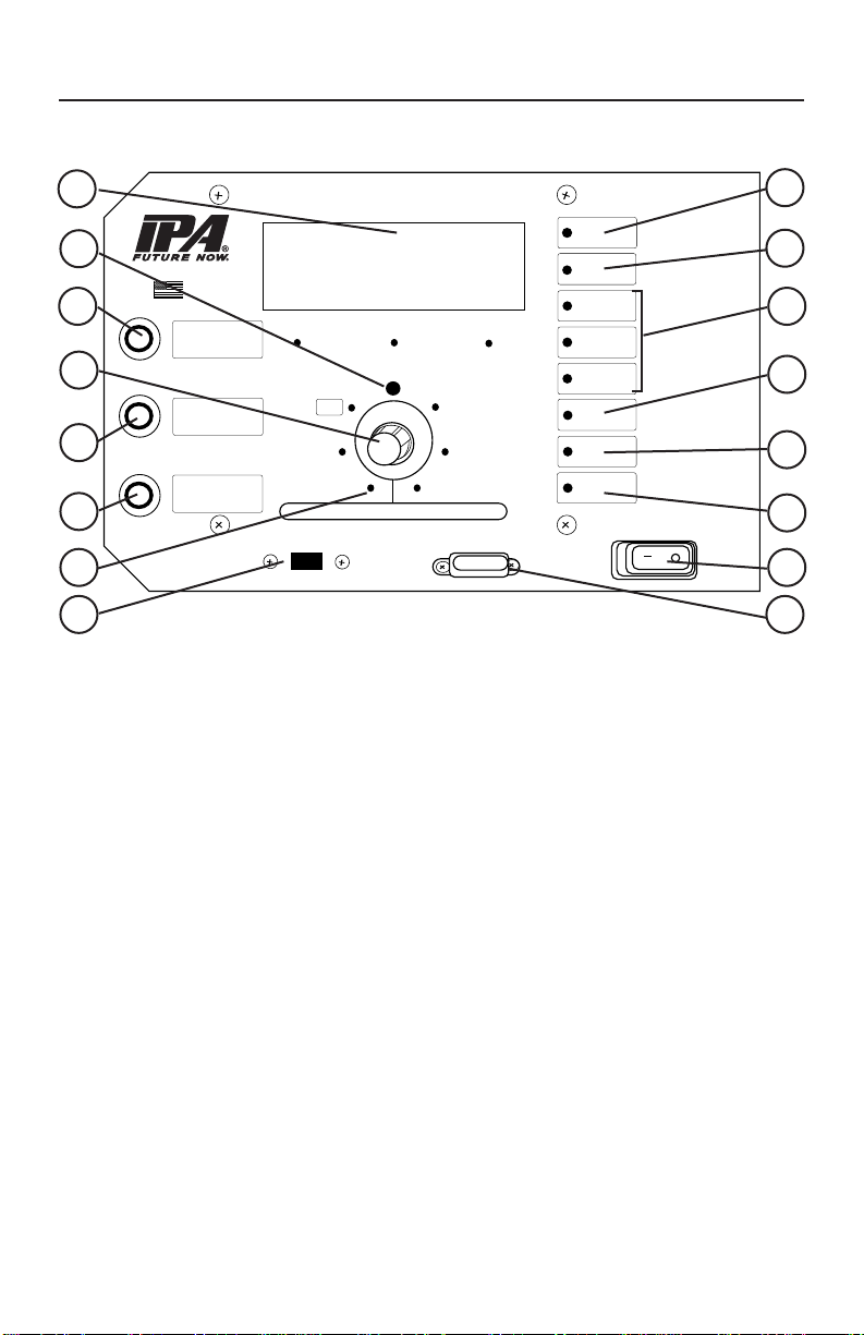
connector. Readings are displayed on the face panel.
This manual covers the Super Ranger MUTT® Series technology. Please consult your
specic model for your exact list of included options. This product is backed by a 1-
year warranty with 24-hour repair or replace service. Should you run into any issues,
please contact IPA®directly at 888-786-7899 or email [email protected].
1.1 Testing Functions
• ABS Testing:
- Read and clear codes
- Displays diagnostic troubleshooting information
- Accesses ECU data: manufacturer, make, model, etc.
- Automatically detects corroded ABS wires and faulty ECU's with patent-
pending technology
• Electrical Testing (12 Volt Operation):
- Automatic cross, open, overload, short and ground fault detection
- Highly accurate digital ammeter with 5mA resolution
- Chase down short circuits with Pulsar®mode
- Ground failure detection: differentiates between wire and chassis ground
1.2 Registering Your Tester’s Warranty
There are two options for registering your tester for warranty:
• Complete the included warranty card and mail it to:
Innovative Products of America
234 Tinker Street
Woodstock, NY 12498
• Complete the online warranty registration at https://www.ipatools.com/warranty
1

2
PART 2: SAFETY INSTRUCTIONS
2.1 Important Information
Itisimportanttoread,understandandfollowallsafetymessagesandinstructions
printedinthismanualandontheequipmentbeforeoperating.Ifsafetyinformation
is not heeded, serious injury or death of the operator or bystanders may occur.
Danger
Indicates a hazardous situation, if not avoided, will result in death or serious injury. The
possible hazards are shown in the adjoining symbols or explained in the text.
Warning
Indicates a hazardous situation, if not avoided, could result in death or serious injury.
The possible hazards are shown in the adjoining symbols or explained in the text.
Caution
Indicates a hazardous situation, if not avoided, may result in minor or major injury. The
possible hazards are shown in the adjoining symbols or explained in the text.
The following safety alert symbols are used in this manual.
Symbol 1: Potential burn hazard. Sparks from electrical shorts can ignite ammable
liquids such as fuel or oil. Heat from electrical overloads can cause re hazards.
Symbol 2: Potential electrical hazard. Batteries have enough electrical energy
potential to ignite ammable liquids such as fuel or oil. Wire overloads can cause
electrical failures. Shock hazard exists.
Symbol 3: Potential explosive air hazard. Pneumatic pressures used with this
equipment can cause explosive failures on damaged equipment.
Symbol 4: Potential eye hazard. Wear OSHA approved safety glasses. Battery acid
and high air pressures create hazardous situations for eyes.
Symbol 5: Potential chemical burn hazard. Wear protective gloves. Battery acid is
corrosive and can cause skin damage.
Symbol 6: Potential electrical hazard. Electrical energy can cause heat and burn hazards.
Symbol 7: Potential re hazard. Use caution with ammable liquids such as fuel and
oil. Electrical shorts can ignite ammable liquids and wiring.
Symbol 8: Important information is stated.

3
2.2 Lithium Battery Safety/Hazard Information
Risk of Fire, Serious Injury and/or Property Damage
• Do not modify, disassemble or alter the
lithium battery.
• Avoid vibrating, puncturing, tampering, or
contacting with metal.
• Only use the provided lithium battery charger.
• Never leave lithium battery unattended
while charging.
• Disengage charger if lithium battery gets hot, smokes, swells or becomes odorous.
• If lithium battery leaks uid onto your skin or in your eyes, rinse well with water and
seek medical attention immediately. Do not rub uid on skin or in eyes. Battery
uid can cause real harm if left untreated.
• Keep out of reach of children.
• Risk of re is exacerbated if: battery is not recharged shortly after being fully
discharged; battery is damaged; battery is defective; battery is used/stored at
extreme temperatures; battery is reaching end of life cycle.
• Recharge lithium battery within 24 hours of full discharge.
• Do not charge lithium battery at temperatures below 40ºF (4°C).
• Do not expose lithium battery to saltwater or similar uids.
• Do not drop lithium battery. If battery is dropped, inspect for damage. If damage
is found, do not use.
• Discharge lithium battery at temperatures between 4ºF and 140ºF (-20°C and 60°C).
• Store lithium battery at temperates between 40ºF and 80ºF (4°C and 27°C).
• A frequently used lithium battery may be stored at 100% charge. If used infrequently,
store lithium battery at 40% to 70% charge.

2.3 General Charger Use
Risk of Electric Shock and Fire
• Before connecting charger to unit, make sure Power
switch is set to OFF.
• Do not remove or bypass the grounding pin.
• Do not operate charger with damaged cord or plug.
Replace cord or plug immediately if damage occurs.
• Position power cord and charger cables away from
the hood, doors and hot or moving engine parts
where they could be damaged.
• Unplug power cord by grasping and pulling on the plug, rather than the cord when
disconnecting charger from outlet.
• Charger power cord uses equipment-grounding conductor and a grounding
plug. Plug only into a 120V AC outlet that is correctly installed and grounded in
accordance with all ordinances and local codes.
• Unplug power cord from outlet before cleaning or maintaining tester and charger.
Turning off controls does not reduce the risk of electric shock.
• Do not operate charger after a sharp impact, drop or any other damage. Do not
disassemble charger.
• Use only recommended attachments.
• Do not charge a frozen battery.
• Do not overcharge a battery.
• Electric shock or re can cause injury.
Risk of Entanglement
• Keep yourself, clothing and battery charger leads clear of moving parts such as
fan blades, pulleys, hood and doors.
• Moving parts can cause injury.
Risk of Burns
• Batteries can produce short circuit current high enough to weld jewelry such as
rings, bracelets and watches. You must remove them before working near batteries.
• Short circuits can cause injury.
DO NOT
Plug Directly Into
AC Wall Outlet
4

5
PART 3: WHAT’S INCLUDED
Use the Provided Reference Numbers When
Ordering Products and Parts Above
Toll Free: 888-786-7899
3.1 Included Parts and Accessories:
12-BUTTON REMOTE CONTROL
#MUT-RM12
PREV.
CIRC
.
NEXTCIRC.
AI
RB
RA
KES
ALLCIRC. ONHAZARDS AUTOCYLE
ABS/AUX
L
EFT
T
URN
CLEARAN
CE
TA
IL/TAG
R
I
G
HT T
U
RN
BRAKELIGHT
Rubber Gasket
Lid Lock
Control Knob
Enclosure
Chassis Ground Input
7-Way Round Socket
Storage
Compartment
Power Switch
LCD Screen
Home Button
Shortcut Button
500mA BATTERY CHARGER
#CHR0001
8-ft. 7-Way Round Pin
Diagnostic Cable
#7900K-1-8-AS2
Mute Button
Fuse

6
PART 4: INITIAL SET-UP
4.1 Specications
Connection Type: 7-Way Round Pin
Power Input: 12V DC
Battery: Lithium Iron Phosphate (LiFePO4)
Ammeter: 5mA—21A
Max Output Current: 10A Continuous
Peek Inrush: 16A @ 30 Seconds
Controls: Remote or Manual
Microprocessor: 2020 High-Speed
Display: Dual-Line, 32 Character, All Environment
Digital LCD Screen
Faceplate: Water-Resistant and Sealed
Buttons: Illuminated Pushbutton Switches
Storage: 6.75" L x 3" W x 7.5" D
Materials: Plastic Case with Steel Control Panel
and Battery Compartment
Weight: 11.3 lbs
Dimensions: 17" L x 9" W x 11" H
4.2 Battery/Power Supply Requirements
The Super Ranger MUTT®is shipped with an internal
Lithium Iron Battery LiFePO4. It should only be charged
with the supplied battery charger, which is specially
designed to charge lithium batteries. The use of another
type of battery charger will void the product warranty.
4.3 Shipping
Lithium batteries should never be air shipped fully charged. They must be discharged
to less than 20% capacity. The voltage of the battery should read 12.9V or less prior
to shipping the battery.
4.4 Auto Shutdown Feature
If left inactive for a period of 20 minutes, the Super Ranger MUTT®will enter a Sleep
mode and power down.
• A sound is emitted every 20 seconds during Sleep mode.
• Activation of the control knob will cancel Sleep mode.
DC POWER
12 Volt DC Only

7
PART 5: GENERAL CONTROLS AND OPERATIONS
5.1 Control Panel
A. LCD Screen
Shows voltage, amperage, ABS readings, circuit settings and system menus.
B. Ground Integrity Indicator
Solid green LED indicates good ground. Blinking green LED indicates a bad/poor
ground. Ground integrity is automatically veried when power is turned on.
C. Back/Home Button
Toggles display between reading voltage/current/amperage/ABS diagnostics and
the last viewed menu or function screen.
D. Control Knob
Used to select trailer circuits or to navigate system menus.
E. Shortcut Button
Activates custom shortcut. Shortcuts can be set by holding button for three seconds.
F. Mute Button
Mute all alerts.
G. Circuit Indicators
The small green LEDs illuminate or blink in testing phase.
H. USB Port
Used to update rmware. NOT for charging.
I. Voltage Indicator
Green LED indicates fully charged battery. Amber LED indicates battery will need to
be charged soon. Red LED indicates battery needs to be charged immediately.
P
R
E
S
S
T
O
S
E
L
E
C
T
VOLTAGE
INDICATOR
REVERSE
POLARITY
CROSS
CIRCUIT
OPEN
CIRCUIT
SHORT/
OVERLOAD
ABS ECU
POWER
ABS SIGNAL
QUALITY
ABS FAULT
STATUS
ALERTS
AUX 2
AUX 1
CLEARANCE
L/SIGNAL
R/SIGNALTAIL/TAG
BRAKE L.
ABS
GROUND
Green:..... Fully charged battery
Amber:.... Charge battery soon
Red:........ Charge battery
Switch battery leads
Two or more circuits
are crossed
Insufficient load
or bad return ground
Red:....... Short to ground
Amber:... Overload condition
Green:..... Detected
Amber:..... Abnormal power draw
Red:......... Not detected
Green:..... Good signal
Amber:..... Poor signal
Red:......... No signal
Green:..... No fault(s) detected
Amber:..... Stored faul(s) detected
Red:......... Active fault(s) detected
MUTE:
Disable all sound
and audible alerts
BACK/HOME:
Press once for previous
screens; Twice for home
H
O
L
D
F
O
R
M
E
N
U
FUSE
SHORTCUT:
Press to activate; Hold
for 3 seconds to change
Patents Pending
FIRMWARE UPDATE PORT
NOT FOR CHARGING
FUSE
POWER
OFF ON
SUPER RANGER MUTT®
www.ipatools.com •845-679-4500
STATUS
MADE
IN USA
TURN KNOB TO SELECT CIRCUIT OR NAVIGATE MENU
A
B
D
C
F
E
G
I
J
K
L
M
N
O
H P

8
J. Reversed Polarity Indicator
Indicates when battery leads need to be switched due to reversed polarity.
K. Trouble Warning Indicators
Flashing red LEDs indicate problems that may exist in a selected circuit. This
includes the Cross Circuits indicator, Open Circuits indicator and Overload indicator.
L. ABS ECU Power Indicator
Indicates health status of ECU circuit by analyzing electronic signature of ABS ECU.
M.ABS Signal Quality Indicator
Indicates the communication status of ABS computer through proprietary technology.
LED colors display the specic status and should be referenced in relationship to the
ABS ECU Power and ABS Fault Status indicators.
N. ABS Fault Status Indicator
Indicates if any types of ABS faults are present on the trailer.
O. Main System Power Switch
Powers on or shuts off the Super Ranger MUTT®.
P. 30 Amp Fuse Socket
Overload protection.
5.2 Using the 12-Button Remote Control
The included 12-button remote control is preprogrammed to your Super Ranger
MUTT®and should never lose its programming. In the event that you suspect your
remote has lost its programming, contact technical support at 888-786-7899 or email
The supplied key fob battery for the remote control is 12V, Alkaline Energizer type A23. A
Gold Peak type 23A or Duracell MN21 battery can also be used.
How to Program the 12-Button Remote
1. Press and hold the top-center button while
turning the tester’s main power on.
2. Continue to hold the button for two seconds
and then release.
3. Your remote control is now programmed.
How to Use the 12-Button Remote
Pressing each button will select the
corresponding circuit on the MUTT®
(Pressing and holding the ABS/AUX or Brake
Light button will latch both circuits on.) 12-Button Remote Control
WARNING: Inclement weather, nearby power transformers and closely parked
trailers may reduce the remote signal.

9
PART 6: ELECTRICAL/LIGHTING TESTING
Complete the pretesting checklist prior to all testing procedures.
The Super Ranger MUTT®is microprocessor controlled and features a special diagnostic
rmware, designed to speed up your inspection process. The MUTT®will power the
selected electrical circuits and instantly alert you to any signs of a faulty condition. To
properly utilize the diagnostic features, a complete scan of the trailer’s electrical
system should be performed at the front of the trailer using the MUTT®prior to
a walk-around inspection. If any wiring faults are present, the MUTT®will blink or
sound, alerting you to the issue. Only a one-time, walk-around/visual inspection is
needed to conrm that each individual light bulb is properly illuminating.
6.1 Pretest Checklist
The pretesting checklist should always be completed prior to using the Super
Ranger MUTT®.
Unit Placement
• Place the tester on a at, level surface.
• Chock trailer wheels to avoid rolling.
Maintain Connectors
Dielectric grease should be used on all connections to avoid corrosion. If a bad
connection exists at the terminal junction, you may get an erroneous reading and the
tester will not work properly.
• Make sure you have a solid connection in the socket.
• Be certain the 7 pins in each plug are clean and spread to the proper size.
• Always check the connector pins on the tester for proper expansion. Over time,
the pins may bend in slightly resulting in a poor connection between the connector
and the cable ends. A at head screwdriver can be used to expand the pins until
a tight connection is made.
NOTE: Some advanced functions may not be listed on the face panel, so it is
important to read the manual in its entirety to ensure that you are getting the full use
of this diagnostic system.

10
6.2 Selecting a Circuit
Circuits can be selected for testing manually, via remote control or by initiating Auto
Cycle mode.
Manually
1. Turn the control knob to select a circuit. The
control knob is automatically set to Ground
Integrity when power is turned on.
12-Button Remote Control
1. Press and release the desired circuit’s button.
2. Press the Next or Previous Circuit buttons to
cycle through circuits.
Auto Cycle Mode
Auto Cycle mode automatically tests one circuit at a time in a clockwise rotation.
Manually
1. Access Auto Cycle mode as a shortcut setting
via the Shortcut botton.
2. A ve-second delay commences between
circuit sections.
3. Circuits are automatically tested one at a time
in a clockwise rotation.
4. To cancel Auto Cycle mode, momentarily press
and release or turn the control knob.
12-Button Remote Control
1. Press and release the Auto Cycle button on the
12-Button Remote. The AUX2 indicator should
illuminate.
2. A ve-second delay commences between circuit
sections.
3. Circuits are automatically tested one at a time in
a clockwise rotation.
4. To cancel Auto Cycle mode, momentarily press
and release or turn the control knob.
NOTE: Auto Cycle mode does not work when ABS or Brake Light circuits are selected.
P
R
E
S
S
T
O
S
E
L
E
C
T
VOLTAGE
INDICATOR
REVERSE
POLARITY
CROSS
CIRCUIT
OPEN
CIRCUIT
SHORT/
OVERLOAD
ABS ECU
POWER
ABS SIGNAL
QUALITY
ABS FAULT
STATUS
ALERTS
AUX 2
AUX 1
CLEARANCE
L/SIGNAL
R/SIGNAL
TAIL/TAG
BRAKE L.
ABS
GROUND
Green:..... Fully charged battery
Amber:.... Charge battery soon
Red:........ Charge battery
Switch battery leads
Two or more circuits
are crossed
Insufficient load
or bad return ground
Red:....... Short to ground
Amber:... Overload condition
Green:..... Detected
Amber:..... Abnormal power draw
Red:......... Not detected
Green:..... Good signal
Amber:..... Poor signal
Red:......... No signal
Green:..... No fault(s) detected
Amber:..... Stored faul(s) detected
Red:......... Active fault(s) detected
MUTE:
Disable all sound
and audible alerts
BACK/HOME:
Press once for previous
screens; Twice for home
H
O
L
D
F
O
R
M
E
N
U
FUSE
SHORTCUT:
Press to activate; Hold
for 3 seconds to change
Patents Pending
FIRMWARE UPDATE PORT
NOT FOR CHARGING
FUSE
POWER
OFF ON
SUPER RANGER MUTT®
www.ipatools.com •845-679-4500
STATUS
MADE
IN USA
TURN KNOB TO SELECT CIRCUIT OR NAVIGATE MENU

11
6.3 Ground Integrity Test
Each time the Super Ranger MUTT®is powered on, it automatically runs a Ground
Integrity Test. A good ground connection must be established for the MUTT®to
operate a trailer’s electrical system.
1. Immediately after power up, the green lights around the control knob will illuminate.
2. A solid/healthy ground connection is indicated by a steadily illuminated Ground
Integrity indicator.
3. Bad/poor ground or bad cable condition is indicated by all of the LEDs blinking
simultaneously.
4. When one or more green circuit LEDs blink while the Ground Integrity indicator is
steadily illuminated, it indicates that a solid ground has been established, but an
open circuit has been detected. Refer to OPEN CIRCUIT on the next page.
Chassis and Pin Grounds
A poor ground warning may be an indication that the connected trailer is only wired for
chassis ground. There are two ground types. 1) Pin Ground: The ground wire from each
light assembly is wired through the main harness up into the trailer plug. 2) Chassis
Ground: The ground wire from each light assembly is grounded directly to the trailer
chassis. Ground with the truck is established at the king pin.
GOOD GROUND BAD/POOR GROUND
NOTE: The Super Ranger MUTT®cannot monitor ground condition while selecting
circuits. A sudden loss of ground while testing circuits will present as open circuits on
each selected circuit. To conrm ground status, turn control knob back to the ground
position. While in ground position, the Super Ranger MUTT®continuously monitors
the ground status.
NOTE: DO NOT assume a bad ground warning is a result of a faulty trailer. Check
cable connection.

12
6.4 Fault Indication
Open Circuit
An open circuit fault warning is triggered when the circuit draws under 5mA of power.
The Super Ranger MUTT® has a circuit detection resolution of 5mA. When the Super
Ranger MUTT®senses no load, it is often a symptom of a disconnected wire, cut wire,
poor pin connection or bad return ground. The tester can detect open circuits in two
ways.
1. During Ground Integrity Test: An individual
circuit will blink and no audible alerts will
be present.
2. During Circuit Selection: The LCD screen will
indicate the type of fault. The corresponding
circuit’s LED and alert indicator will ash, and
the tester will provide an audible alert (beep).
Crossed Circuits
The Super Ranger MUTT®indicates that two or more circuits are back feeding or
crossed. This can be a symptom of two wires in the same harness wearing through
their insulated coating and connecting.
1. When a crossed circuit is identied, the LCD
screen will display “CROSS CIRCUIT”. The
circuit LED that should not be powered and
needs correcting will ash, and the tester will
provide an audible alert (beep).
Short/Overloaded Circuit
Short circuits or overloads can occur when a positive/hot wire touches ground or the
load on the circuit exceeds the allowable current or amperage draw (factory default is
21 amps). A short or overload can also be a result of faulty lights or poor connections.
1. If a short or overloaded circuit is suspected,
the tester will instantly suspend power for
three seconds and enter PULSAR®mode
until the short is removed.
2. The LCD screen will indicate the type of
fault. The corresponding circuit LED and
alert indicator will ash, and the tester will
provide an audible alert (beep).
3. During PULSAR®mode, the tester enters a three-second countdown sequence.
When the countdown completes, the tester will attempt to restore power to the
circuit. If a short is still present, steps 1-3 will automatically repeat.
NOTE: Open Circuit indicator will only illuminate during circuit selection.
NOTE: In some cases, a crossed circuit may be a normal function of advanced
diagnostic testing, such as with certain ABS systems.
NOTE: PULSAR® mode can be a useful tool for nding dead and intermittent shorts.
P
R
E
S
S
T
O
S
E
L
E
C
T
VOLTAGE
INDICATOR
REVERSE
POLARITY
CROSS
CIRCUIT
OPEN
CIRCUIT
SHORT/
OVERLOAD
ABS ECU
POWER
ABS SIGNAL
QUALITY
ABS FAULT
STATUS
ALERTS
AUX 2
AUX 1
CLEARANCE
L/SIGNAL
R/SIGNALTAIL/TAG
BRAKE L.
ABS
GROUND
Green:..... Fully charged battery
Amber:.... Charge battery soon
Red:........ Charge battery
Switch battery leads
Two or more circuits
are crossed
Insufficient load
or bad return ground
Red:....... Short to ground
Amber:... Overload condition
Green:..... Detected
Amber:..... Abnormal power draw
Red:......... Not detected
Green:..... Good signal
Amber:..... Poor signal
Red:......... No signal
Green:..... No fault(s) detected
Amber:..... Stored faul(s) detected
Red:......... Active fault(s) detected
MUTE:
Disable all sound
and audible alerts
BACK/HOME:
Press once for previous
screens; Twice for home
H
O
L
D
F
O
R
M
E
N
U
FUSE
SHORTCUT:
Press to activate; Hold
for 3 seconds to change
Patents Pending
FIRMWARE UPDATE PORT
NOT FOR CHARGING
FUSE
POWER
OFF ON
SUPER RANGER MUTT®
www.ipatools.com •845-679-4500
STATUS
MADE
IN USA
TURN KNOB TO SELECT CIRCUIT OR NAVIGATE MENU

13
6.5 Activating Hazard Lights
The four-way ashers on the trailer can be activated manually or with the remote control.
Manually
1. To activate/deactivate, access Hazard mode
as a shortcut setting via the Shortcut botton.
12-Button Remote Control
1. To activate/deactivate, press and hold the
Hazards button.
6.6 All Circuits On (Override) Mode
All Circuits On mode will engage all electrical circuits at the same time. While short
circuit sensing is operational in this mode, if a short circuit is found, the Super Ranger
MUTT®will not be able to identify which circuit is the cause of the short. Open and
crossed circuit sensing is not operational in this mode.
On trailers using incandescent bulbs, All Circuits On mode will typically result in an
overload because the amperage draw will exceed the maximum of 20 amps.
All Circuits On mode can be accessed manually or by remote control.
Manually
1. To activate/deactivate, access All Circuits On
mode as a shortcut setting via the Shortcut
botton.
12-Button Remote Control
1. To activate/deactivate, press and hold the All
Circ. On button.
NOTE: Does not work when ABS or Brake Light circuits are selected.
P
R
E
S
S
T
O
S
E
L
E
C
T
VOLTAGE
INDICATOR
REVERSE
POLARITY
CROSS
CIRCUIT
OPEN
CIRCUIT
SHORT/
OVERLOAD
ABS ECU
POWER
ABS SIGNAL
QUALITY
ABS FAULT
STATUS
ALERTS
AUX 2
AUX 1
CLEARANCE
L/SIGNAL
R/SIGNAL
TAIL/TAG
BRAKE L.
ABS
GROUND
Green:..... Fully charged battery
Amber:.... Charge battery soon
Red:........ Charge battery
Switch battery leads
Two or more circuits
are crossed
Insufficient load
or bad return ground
Red:....... Short to ground
Amber:... Overload condition
Green:..... Detected
Amber:..... Abnormal power draw
Red:......... Not detected
Green:..... Good signal
Amber:..... Poor signal
Red:......... No signal
Green:..... No fault(s) detected
Amber:..... Stored faul(s) detected
Red:......... Active fault(s) detected
MUTE:
Disable all sound
and audible alerts
BACK/HOME:
Press once for previous
screens; Twice for home
H
O
L
D
F
O
R
M
E
N
U
FUSE
SHORTCUT:
Press to activate; Hold
for 3 seconds to change
Patents Pending
FIRMWARE UPDATE PORT
NOT FOR CHARGING
FUSE
POWER
OFF ON
SUPER RANGER MUTT®
www.ipatools.com •845-679-4500
STATUS
MADE
IN USA
TURN KNOB TO SELECT CIRCUIT OR NAVIGATE MENU

14
PART 7: ABS DIAGNOSTICS
7.1 Accessing ABS Codes
The Super Ranger MUTT® is equipped with integrated ABS diagnostics and allows for
the ability to access and clear ABS fault codes via the control panel LCD.
ABS Explained
Modern trailers with ABS systems store fault codes when an error or malfunction
occurs. Trailers with ABS systems typically have an amber colored light labeled “ABS”
located on the road side of the trailer. When an active fault is present, this light will
illuminate, alerting the driver or technician that there is an active fault within the ABS
system. When an ABS fault is active, the problem must be resolved, and the ABS
light cleared in order for the trailer to pass inspection. ABS system faults are often
associated with open circuits and loss of communication to the wheel speed sensors,
or loss of power to the ABS ECU. While there are several ABS manufacturers, they all
generally follow the SAE recommendations for how to display codes. These codes are
traditionally accessed through two methods.
The simple analog method is commonly referred to as the Blink Code method. Each
manufacturer differs in the way blink codes are initiated. Blink codes are a slower and
more tedious way of retrieving ABS information with the major deciency being most
manufacturers do not allow you to clear codes via the Blink Code Method.
The method of using a scan tool to retrieve codes in commonly referred to as the
Digital Fault method. Digital fault codes can be viewed along with the denition of
the fault on the screen which improves troubleshooting time. The digital method also
allows for codes to be cleared which prevents the technician from having to jack up
the trailer and spin the wheels or pull it down the road just to clear a code.
SUPPORT LINKS AND INFORMATION: If you suspect an issue with the tester’s
software or hardware, please call IPA®at 888-876-7899 or email [email protected].
For issues with the trailer or ECU modules, please contact the ABS ECU manufacturer.
The most common manufacturers are Meritor (www.meritor.com), WABCO
(www.wabco-auto.com), Haldex (www.haldex.com), Bendix (www.bendix.com) and
Gen2 (www.gen2abs.com).

15
Voltage on Baery
(Vbat)
Odometer: Total
(TOTAL)
Odometer: Trip
(TRIP)
VIN Number
(VIN)
Serial Number
(SN)
Model
(Mdl)
Manufacturer
(MFG)
CLEAR All CODES
(CLR ALL CODES)
STORED CODES
ACTIVE CODES
Mdl: SELECT 1M
Mfg: HALDEX
SN: E502295
VIN:1HG CM82633
Trip: 10,000.0
Total: 10,000.0
Vbat: 12.0V
(Example)
(Example)
(Example)
(Example)
(Example) (Example)
(Example)
MAIN MENU
ABS DETECTED *Works with most
makes and models*
M
E
N
U
C
O
N
T
R
O
L
7.2 Manual Controls
In this method, the user must use both the press function and the turn function of
the control knob to access various menus and read through ABS troubleshooting
information that is available within the LCD screen.
Once the tester is turned on and ABS is detected, you can turn the control knob to
cycle through menus or sub-menus. Press the control knob to access the sub-menus.
The Super Ranger MUTT® communicates with the trailer’s ABS ECU in real time,
via IPA®’s proprietary internal ABS PLC communication module. This module is
automatically activated as long as the ABS/AUX circuit is selected/powered up by the
tester. Once activated, the ABS module will send information request commands to
the trailer’s ECU. The trailer’s ECU will automatically broadcast back the ECU make,
model, VIN, and mileage along with other basic information. This information is then
stored inside the internal computer of the tester.
When fault codes or clear fault commands are requested, the ABS PLC communication
module will send the command to the trailer’s ECU. The user must then request fault
codes again to verify that there are no active faults. Each Super Ranger MUTT®
provides ABS data status lights which indicate the status of information either being
sent to the trailer in the form of commands, or information being broadcasted from the
trailer to the tester. When troubleshooting ABS connectivity issues, it is imperative for
the technician to view these status LEDs. Failing to view the status LEDs could result
in false assumptions such as a faulty ABS computer, broken ABS light and others.
Note: Turning the control knob clockwise allows you to scroll through each sub-menu.
Turning the control counterclockwise will back you out one sub-menu at a time.

16
Accessing Active Faults (Sub-Menu #1)
With the ACTIVE FAULTS Sub-Menu 1 selected and the Active SID and FMI codes
displayed, turn the control knob clockwise to cycle through the fault codes (Fig. 1-A).
Press the control knob (Fig. 1-B) to read the fault description (Fig. 1-C).
Accessing Stored Faults (Sub-Menu #2)
With the STORED FAULTS Sub-Menu 2 selected and the Stored SID and FMI codes
displayed, turn the control knob clockwise to cycle through the fault codes (Fig. 2-A).
Press the control knob (Fig. 2-B) to read the fault description (Fig. 2-C).
Clear All Codes (Sub-Menu #3)
With the CLR ALL CODES Sub-Menu 3 selected, the screen will display CLR? NO/
YES. Turn the control knob to YES or NO depending on your desire (Fig. 3-A). Press
the control knob to make your selection (Fig. 3-B).
Note: You can only clear stored codes. Clearing a code will return you to the main menu.
SID002 FMI007 C1 ABS AXEL 1LEFT
(SUB MENU #1)
ACTIVE FAULTS
(Fig. 1-C)(Fig. 1-A) (Fig. 1-B)
(FAULT EXAMPLE)
FAULT
1
FAULT
2
FAULT
3
FAULT
4
ACTIVE CODES
SID002 FMI007 C1 ABS AXEL 1LEFT
(SUB MENU #2)
STORED FAULTS
(Fig. 2-C)(Fig. 2-A) (Fig. 2-B)
(FAULT EXAMPLE)
FAULT
1
FAULT
2
FAULT
3
FAULT
4
STORED CODES
Clr? [NO]/yes Clr?no/[YES]
(SUB MENU #3)
CLEAR ALL CODES
(Fig. 3-A) (Fig. 3-B)
CLEAR All CODES
(CLR ALL CODES)

17
7.3 Failure Mode Identier (FMI) Assignments
The Failure Mode Identier, FMI, describes the type of failure detected in the subsystem
identied by the PID or SID. The FMI and either the PID or SID combine to form a given
diagnostic code (see PID 194 for added clarication). The remaining failure mode
identiers would be assigned by the SAE Truck and Bus Low Speed Communications
Network Subcommittee if additional common failure modes become detectable.
0Data valid but above normal operational range (that is, engine overheating)
1Data valid but below normal operational range (that is, engine oil pressure too low)
2Data erratic, intermittent, or incorrect
3 Voltage above normal or shorted high
4 Voltage below normal or shorted low
5 Current below normal or open circuit
6 Current above normal or grounded circuit
7 Mechanical system not responding properly
8Abnormal frequency, pulse width, or period
9Abnormal update rate
10 Abnormal rate of change
11 Failure mode not identiable
12 Bad intelligent device or component
13 Out of calibration
14 Special instructions
15 Reserved for future assignment by the SAE Subcommittee
This manual suits for next models
1
Table of contents
Other iPA Test Equipment manuals

iPA
iPA SMART MUTT 9004M User manual

iPA
iPA SMART MUTT 9004A User manual

iPA
iPA 9102 User manual

iPA
iPA SMART MUTT X User manual

iPA
iPA NATO MUTT M2000 User manual

iPA
iPA Alpha MUTT 5700 User manual

iPA
iPA LIGHT RANGER MUTT 9101 User manual

iPA
iPA SMART MUTT 9004M User manual

iPA
iPA SMART MUTT 9004A User manual

iPA
iPA HEAVY RANGER MUTT 9102 User manual