8
SHORT CIRCUIT AND OVERLOAD TESTING
Short Circuit: When a positive power source (12V +) is directly connected to or touching
the ground (-), wire insulation can wear through due to vibration; exposed copper wire can
make contact with the metal trailer frame resulting in a short circuit and a blown fuse in
the vehicle.
Overload: When the load (lights and/or electric brakes) attempts to draw more current
(amps) than the circuit was designed to handle, this often results in blown fuses.
Summary: The Ranger MUTT® is capable of providing up to 10A of current to a selected
circuit. It is equipped with an internal, auto-resetting thermal circuit breaker, which is
designed to remove power to the selected circuit when the load exceeds 10A in overload
condition. Once power is removed, the circuit breaker requires a 30-second cooldown
cycle until power can be reapplied. If the source of the excessive current draw, i.e., the
overload condition is still present, the circuit breaker will immediately remove power once
again. This process will be repeated until the source of the excessive current draw is
removed. Most small trailers should not exceed 10A per circuit when wired properly. You
should check the specied current draw for each light bulb or LED on the trailer circuit to
determine whether it’s an overload condition, short circuit condition or faulty equipment,
e.g., electric brakes, lights, harnesses, etc.
NOTE: The auto-resetting thermal circuit breaker used in the Ranger MUTT®is thermally
activated and requires a short cooldown time between uses. The more often it is tripped,
the longer the required cooldown time before it will become active again.
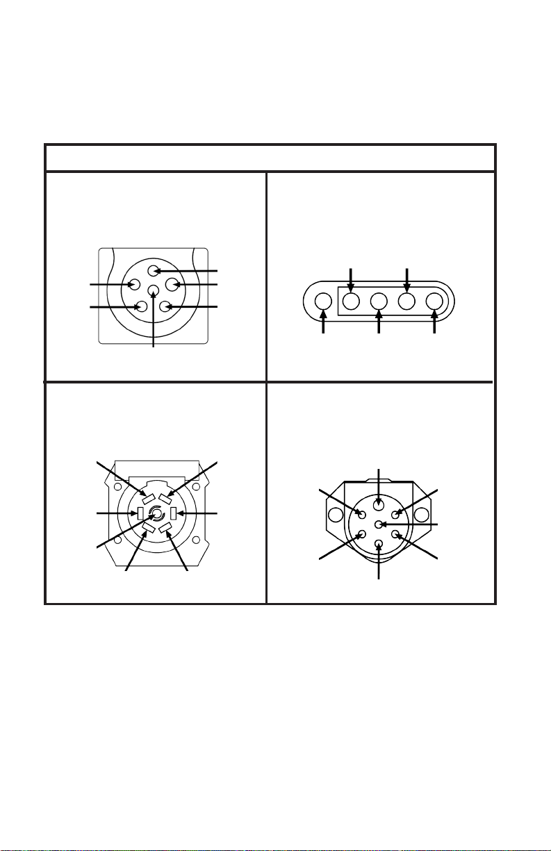
TEST 6-WAY ROUND AND 4/5-PIN TRAILERS WITH
3-WAY ADAPTER
TESTING PROCEDURE
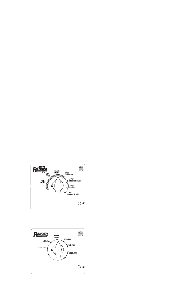
The #9101 Light Ranger MUTT® is designed to test trailers with 6-way round and 4/5-pin
connectors with the use of the 3-way adapter. The faceplate on the Ranger MUTT®shows
which functions are supplied for each pin layout. For example: a 5-pin trailer is wired for
tail lights, left turn, brake lights, right turn and electric brakes, but not 12V aux. or backup
lights. Consequently, when those circuits are selected on the Ranger MUTT®, they do not
power anything on a 5-pin trailer. See g. 2 for the #9101 faceplate layout. The supplied
adapter provides an easy way to plug 4, 5 or 6-pin trailers into the Light Ranger
MUTT . A brief explanation of how to get started is provided below.
1. Plug the 3-way adapter into the 7-way socket on the Ranger MUTT®.
2. Be sure to push rmly until the key is down far enough for the ap to lock in behind it.
3. Plug the trailer into the proper terminal on the 3-way adapter. NOTE: The 5-pin
connector also works for 4-pin trailer sockets.
4. To begin testing the trailer, turn the control knob to the desired circuit
(as indicated on the faceplate).
5. Once the knob is turned to the selected circuit, power is being sent to the
corresponding wire on the trailer.
6. Follow the 7-way pin testing procedure (pg. 7) section for further information.