iPA Alpha MUTT 5700 User manual

1
Innovative Products of America®Incorporated
888-786-7899 • 234 Tinker Street, Woodstock, NY 12498 • www.ipatools.com
© 2018 Innovative Products of America®Incorporated. All rights reserved. This material may not be reproduced, displayed,
modied or distributed without the express prior written permission of the copyright holder. For permission, contact [email protected].
Operator’s Manual
#5700
Alpha MUTT®
Mobile Universal Trailer Tester
Tests Trailers With 7-Way Round Pin Type Connections
(Uses External 12/24 Volt Battery or Power Source)

2
(OEM) Original Equipment Manufacturer USA
LETTER FROM THE PRESIDENT OF IPA®
My name is Peter Vinci and I would like to thank you for your interest in our products.
In today’s world, we have all experienced the lack of service and consideration
demonstrated by many companies after you buy their products. They say whatever
they can to make the sale, and then it’s like pulling teeth to get any service response
out of them. I know this myself rsthand and because of this, I want to be sure that your
experience with IPA®meets your expectations and that IPA®never disappoints you with
our service or customer response.
To prove my commitment to you, if for any reason, you are not happy with one of our
products, or more importantly, with the response from our customer service department,
or any member of the IPA®team, I invite you to contact me directly via my email,
to me than the sale itself. We will not be in business for long if we don’t make you
completely happy with our products and service. I want IPA®to be different and be known
for its quality and service.
With that said, please take a look at our product line. You will see innovative rst time
products that were created to help you do your job faster and better than before.
I would also like to invite you to critique our products. If you can think of a better way to
make them or changes that will make them work better, please contact me directly and I
will be sure to look into it. If you have an innovation and would like some
feedback, give me a call.
From all of us at IPA®, we thank you for taking the time to review our product line and wish
you and your family the very best of everything.
Peter Vinci
President
IPA®
www.ipatools.com
Toll Free: 888-786-7899
Phone: 845-679-4500
Fax: 845-679-4600

3
TABLE OF CONTENTS
PART 1: IMPORTANT SAFETY INSTRUCTIONS 4
PART 2: WHAT’S INCLUDED 7
PART 3: CONTROLS AND PANELS 8
3.1 Left, Right and Back Panels 8
3.2 Electrical Control Panel 9
3.3 Air Brake Control Panel 10
PART 4: SET-UP 11
4.1 Choosing a Battery 11
4.2 Lifting the Unit 11
PART 5: PRETESTING CHECKL IST 12
5.1 Cable Testing Procedure 12
PART 6: GENERAL CONTROLS AND OPERATIONS 13
6.1 Initial Startup and Shutdown 13
6.2 Auto Shutdown Feature 13
6.3 Using the 3-Button Remote Control 14
6.4 Using the 12-Button Remote Control 14
6.5 Using the Tablet 15
PART 7: ELECTRICAL/LIGHTING TESTING 17
7.1 Selecting a Circuit 17
Auto-Cycle Mode 17
7.2 Ground Integrity Test 18
Establishing a Chassis Ground 18
7.3 Fault Indication 19
Open Circuit 19
Crossed Circuits 19
Short/Overloaded Circuit 20
7.4 Activating Hazard Lights 21
7.5 All Circuits On (Override) Mode 22
PART 8: AIR BRAKE TESTING 23
8.1 Testing Set-Up 23
8.2 Setting Desired Working Pressure 24
8.3 Leak Down Testing 24
8.4 Actuating Air Brakes 25
8.5 Emergency Air Exhaust 26
PART 9: ABS BLINK CODE DIAGNOSTICS 27
9.1 Meritor/WABCO Blink Codes 28
9.2 Haldex Blink Codes 29
9.3 Bendix®Blink Codes 34
PART 10: TYPICAL TRAILER WIRING 37
PART 11: MAINTENANCE AND STORAGE 38
PART 12: ADDITIONAL TESTING PROCEDURES 38
PART 13: OPTIONAL ACCESSORIES AND RELATED PRODUCTS 39

4
PART 1: IMPORTANT SAFETY INSTRUCTIONS
IT IS IMPORTANT TO READ, UNDERSTAND AND FOLLOW ALL SAFETY
MESSAGES AND INSTRUCTIONS PRINTED IN THIS MANUAL AND ON THE
EQUIPMENT BEFORE OPERATING. IF SAFETY INFORMATION IS NOT HEEDED,
SERIOUS INJURY OR DEATH TO THE OPERATOR OR BYSTANDERS MAY OCCUR.
DANGER
Indicates a hazardous situation, if not avoided, will result in death or serious injury.
The possible hazards are shown in the adjoining symbols or explained in the text.
WARNING
Indicates a hazardous situation, if not avoided, could result in death or serious injury.
The possible hazards are shown in the adjoining symbols or explained in the text.
CAUTION
Indicates a hazardous situation, if not avoided, may result in minor or major injury.
The possible hazards are shown in the adjoining symbols or explained in the text.
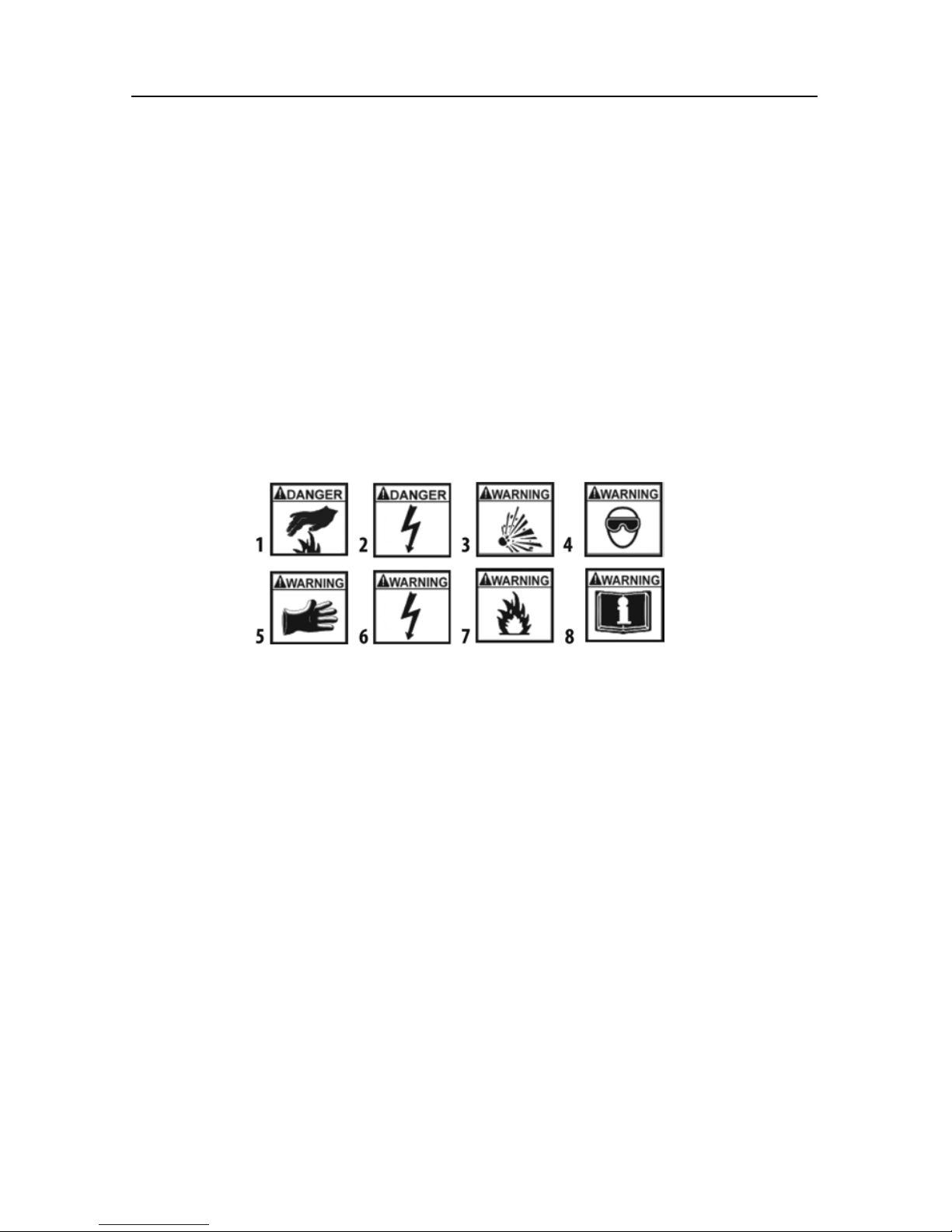
THE FOLLOWING SAFETY ALERT SYMBOLS ARE USED IN THIS MANUAL.
SYMBOL 1: Potential burn hazard. Sparks from electrical shorts can ignite
ammable liquids such as fuel or oil. Heat from electrical overloads can cause re
hazards.
SYMBOL 2: Potential electrical hazard. Batteries have enough electrical energy
potential to ignite ammable liquids such as fuel or oil. Wire overloads can cause
electrical failures. Shock hazard exists.
SYMBOL 3: Potential explosive air hazard. Pneumatic pressures used with this
equipment can cause explosive failures on damaged equipment.
SYMBOL 4: Potential eye hazard. Wear OSHA approved safety glasses. Battery
acid and high air pressures create hazardous situations for eyes.
SYMBOL 5: Potential chemical burn hazard. Wear protective gloves. Battery acid
is corrosive and can cause skin damage.
SYMBOL 6: Potential electrical hazard. Electrical energy can cause heat and
burn hazards.
SYMBOL 7: Potential re hazard. Use caution with ammable liquids such as fuel
and oil. Electrical shorts can ignite ammable liquids and wiring.
SYMBOL 8: Important information is stated.

5
BATTERY GASES, TESTER PREPARATION AND
TESTER/CHARGER LOCATION
RISK OF EXPLOSION
• Gases produced by a battery are highly explosive.
• Wear safety goggles and protective clothing, both
users and bystanders.
• Use in an area having at least four air changes per hour.
• Read, understand and follow all instructions for charger, battery, vehicle and any
equipment used near battery and charger.
• Do not smoke, strike a match, place metal tools on battery or cause a spark in
the vicinity of the battery. When removing battery cables, remove the ground
cable rst.
• Clean terminals before charging battery. During cleaning, keep corrosive particles
from eyes, nose and mouth. Use baking soda and water to neutralize acid and
help eliminate airborne corrosion.
• Never allow clamps on charger cables to touch each other.
• Do not expose tester or charger to rain, snow or wet conditions.
• Do not allow battery gases or acid to contact MUTT®cabinet. Do not place
charger directly above or below battery.
• Fill battery to level specied by battery manufacturer using distilled water.
• Do not remove cell caps while charging per manufacturer’s instructions.
• Make sure tester cable clamps make tight connections.
• Battery explosion can cause injury.

6
GENERAL CHARGER USE
RISK OF ELECTRIC SHOCK AND FIRE
• Before connecting charger cable to unit, make sure
controls are set to OFF.
• Do not remove or bypass the grounding pin.
• Do not operate charger with damaged cord or plug.
Replace cord or plug immediately if damage occurs.
• Position power cord and charger cables away from the hood, doors and hot or
moving engine parts where they could be damaged.
• Unplug power cord by grasping and pulling on the plug, rather than the cord
when disconnecting charger from outlet.
• Charger power cord uses an equipment-grounding conductor and a grounding
plug. Plug only into a 120V AC outlet that is correctly installed and grounded in
accordance with all ordinances and local codes.
• Unplug power cord from outlet before cleaning or maintaining tester and charger.
Turning off controls does not reduce the risk of electric shock.
• Do not operate charger after a sharp impact, drop or any other damage. Do not
disassemble charger.
• Use only recommended attachments.
• Do not charge a frozen battery.
• Do not overcharge a battery.
• Use charger only on lead-acid automotive batteries. Do not use charger to
charge dry-cell batteries.
• Electric shock or re can cause injury.
RISK OF ENTANGLEMENT
• Keep yourself, clothing and battery charger leads clear of moving parts such as
fan blades, pulleys, hood and doors.
• Moving parts can cause injury.
RISK OF BURNS
• Batteries can produce a short circuit current that is high enough to weld jewelry
such as rings, bracelets and watches. You must remove them before working near
batteries.
• Short circuits can cause injury.
DO NOT
Plug Directly Into
AC Wall Outlet

7
PART 2: WHAT’S INCLUDED
INCLUDED PARTS AND ACCESSORIES
Use the Provided Reference Numbers When Ordering
Products and Parts Above
Toll Free: 888-786-7899
12' 7-WAY CABLE
#7900K-1-12AS
12' RED GLADHAND
#7900AP-12RED-FX
10" TABLET
#5700-TAB
BATTERY JUMPER
CABLE
#5700-BLKJMPR-AS
FEMALE 2 PRONG
PLUG POWER ADAPTER
#7900K-93
BATTERY JUMPER
CABLE
#5700-REDJMPR-AS
10' CHASSIS
GROUND CABLE
#7900K-2BCHAS
RAIN COVER
#CVR-0002
3-BUTTON REMOTE
CONTROL
#MUT-RM3-9005A/8
12-BUTTON REMOTE
CONTROL
#MUT-RM12
PREV.CIRC.
NEXTCIRC.
AIRBRAKES
ALLCIRC.ONHAZARDS AUTOCYLE
ABS/AU
X
LEFT TURN
CLEARANCE
TAIL/TAG
RIGHT TURN
BRAKELIGHT
12' BLUE GLADHAND
#7900AP-12BLU-FX
LCD Menu Screen
Electrical
Testing Panel
Circuit Indicators
Control Knob
Hazards
Fuse
Internal Air
Regulator
Face Shield
10"Tablet
7-Way Round Pin
Cable Out to Trailer
Service-Side Air Out
(Blue Hose)
USB for Data
Emergency-Side Air
Out (Red Hose)
Lid Lock
Battery Compartment
12"Pneumatic Wheels
Locking Castors
7-Way Round Pin
Tester Input
Shop Air
Inlet
Handles
Main Power Switch
USB Tablet
Charging Port
Mute
Emergency-Side
Air Pressure
Gauge
Emergency-Side
Air Ball Valve
Service-Side Air
Ball Valve
Service-Side Brake
Control Switch
Service-Side Air
Pressure Gauge
MICRO USB
#CBL-9INUSBMIC
TABLET CHARGER
#5700-TABCH
POWER CORD
#7900K-80ACORD
Chassis
Ground
Cable

8
A. 7-WAY ROUND PIN CABLE TEST INPUT
For testing the integrity of a 7-way round pin trailer cable. Can also be used to
verify that the MUTT®is operating correctly.
B. SHOP AIR INPUT
A bulk-head air input with external stone lter that is used to connect an air
compressor to the MUTT®for testing air brakes on a trailer.
C. 7-WAY ROUND PIN CABLE OUT TO TRAILER
For connecting 7-way round pin trailer to the MUTT®to test electrical circuits.
D. ABS BLUETOOTH®CONNECTIVITY RECEPTICLE
E. 20 AMP INDEPENDENT POWER INPUT
For connecting external 12V DC 20 amp max. power supply. (Power supply is an
optional accessory, not for battery charging.)
F. SYSTEM BLUETOOTH®CONNECTIVITY RECEPTICLE
G. 12V DC BATTERY TRICKLE CHARGE INPUT (CIGARETTE SOCKET)
For connecting a trickle charger to the MUTT®’s internal battery (battery not
included).
BACK
E
D F
G
PART 3: CONTROLS AND PANELS
An overview of the MUTT®’s controls, inputs, outputs and their functions.
3.1 LEFT, RIGHT AND BACK PANELS
Left Side Right Side
C
A
B

9
3.2 ELECTRICAL CONTROL PANEL
A. LCD MENU SCREEN
B. LCD MENU CONTROL KNOB
Knob activates all menu options and modes.
C. BLUETOOTH®PAIRED INDICATOR
Steady blue light indicates paired device.
D. CONTROL KNOB
Knob activates all electrical test modes and circuits to be diagnosed.
E. CIRCUIT INDICATORS
The small green LEDs illuminate or blink in testing phase.
F. POWER SOURCE SWITCH
Select between Internal Battery, External Power or Power Off.
Center: OFF (battery charge in this position only)
Left: Installed Battery ON
Right: External Power ON (power supply is an optional accessory)
G. TABLET CHARGE PORT
For charging 10"tablet. Not a data port.
H. GROUND INTEGRITY
Solid green LED indicates good ground. Blinking red LED indicates a bad/poor
ground. Ground integrity is automatically veried when power is turned on.
I. TROUBLE WARNING INDICATORS
Flashing red LEDs indicate problems that may exist in a selected circuit. This
includes the Overload Indicator, Open Circuit Indicator and Reversed (Battery)
Polarity Indicator.
J. VOLTAGE INDICATOR
Green LCD indicates fully charged battery. Amber LED indicates battery will need
charge soon. Red LED indicates battery needs charge immediately.
K. REVERSE POLARITY INDICATOR
Indicates when battery leads need to be switch due to reversed polarity.
A
B
D
C
E
F
H
G
I
J
K
L
M
N

10
L. HAZARD BUTTON
Activates the four-way ashers on trailer.
M. 30 AMP FUSE SOCKET
Overload protection.
N. MUTE BUTTON
Mute all alerts.
3.3 AIR BRAKE CONTROL PANEL
A. Emergency-Side Air Pressure Gauge
B. Emergency-Side Air Ball Valve
C. Chassis Ground Outlet
D. Emergency-Side Out
E. Air-Regulator Knob
F. Service-Side Air Pressure Gauge
G. Service-Side Brake Control Switch
H. Service-Side Air Ball Valve
I. USB Data Port (used for rmware updates)
J. Service-Side Out
LEAK DOWON TEST (Emergency/Service): To charge syste
with are, set switch to open fill to desired pressure.
Close switch to shut off air flow and note any pressure
drop through needle movement
TAKE CAUTION: Open emergency side switch to release
parking brake. Open service side switch to actuate service
brakes. To operate service brakes with remote, set switch
to exhaust/remote and press small button on remote control.
CLOSED
psi
0
20
40
60
80 100
120
140
160
CLOSED
EXHAUST
CHASSIS GROUND EMERGANCY SIDE OUT SERVICE SIDE OUT USB DATA PORT
EMERGENCY
SIDE
SERVICE
SIDE
EXHAUST
REMOTE
PULL KNOB TO ADJUST
MAX. 120 PSI
WARNING: CHOCK ALL TRAILER WHEELS
BEFORE APPLYING AIR PRESSURE
AIR BRAKE CONTROLS
PRESSURIZE
OPEN OPEN
psi
0
20
40
60
80 100
120
140
160
INLET AIR PRESSURE IS DISPLAYED ON
EMERGENCY SIDE GUAGE: To set pressure,
connect shop air, push switch to opan,
the adjust regualr knob.
Air Brake Control Panel
A
C
D
I
J
B
G
F
H
E

12V BATTERY #1 12V BATTERY #2
ALPHA
MUTT®
Operating
at 24V
JUMPER
POSITIVE
POSITIVE
NEGATIVE
STANDARD 24V WIRING CONFIGURATION
NEGATIVE
12V
Charger
11
PART 4: SET-UP
4.1 CHOOSING A BATTERY
The MUTT®is a 12/24V DC device. Attempting to power
your MUTT®with anything other than a 12 or 24 volt DC
power source will destroy the internal circuitry and void
your warranty.
Manufacturer’s Suggested Battery: Group 31. MUTT®will auto detect 12 or 24 volts.
If 24 volts is required, two smaller 12 volt batteries can be used, but they must be
wired in series.
• Battery Voltage: 12/24V DC
• Battery Type: Lead Acid
• Battery Compartment Dimensions:
14" W x 15 ½" H x 13" D.
• Battery Protection: Inline 30A fuse
for overcharge.
• Battery must be clean and leak free.
• Identify battery polarity.
• Attach ring terminal with red heat shrink to
positive (+) side and ring terminal with black
heat shrink to negative (-) side. Also see
warning indicators on pg. 4. Connections
must only be made to clean terminal rings.
• Any loose or corroded connectors may cause
misdiagnosis or result in erroneous readings.
• Use fully charged battery.
4.2 LIFTING THE UNIT
The MUTT®has three handles for use in maneuvering the unit. It should be noted
that these handles are not intended to be used as lift points. If the unit needs to be
lifted, you MUST use two people and lift from the bottom of the unit. DO NOT use
just the handles for lifting the unit.
Battery Compartment
DC POWER
Do not plug directly into
AC wall outlet
WARNING
DO NOT Use 24V
On 12V Circuits

12
PART 5: PRETESTING CHECKLIST
The pretesting checklist should always be completed prior to using the MUTT®
UNIT PLACEMENT
• Place the tester on a at, level surface.
• Chock trailer wheels to avoid rolling before testing brakes.
MAINTAIN CONNECTORS
Dielectric grease should be used on all connections to avoid corrosion. If a bad
connection exists at the terminal junction, you may get an erroneous reading and the
MUTT®will not work properly.
• Make sure you have a solid connection in the socket.
• Be certain the 7 pins in each plug are clean and spread to the proper size.
• Always check the MUTT®connector pins at the side of the MUTT®for proper
expansion. Over time, the pins may bend in slightly resulting in a poor connection
between the connector and the cable ends. A at head screwdriver can be used
to expand the pins until a tight connection is made.
CABLE TESTING PROCEDURE
The MUTT®has a special cable feature to test 7-way round pin cables for continuity.
The cable testing feature can be used to test a tractor’s cable or the supplied MUTT®
cable. All cables should be tested prior to MUTT®operation.
• Insert each end of the cable into both side connectors on the MUTT®. Be sure to
push the cable ends in rmly until they reach the bottom of the connector.
• Turn Power Source Switch to a desired power supply.
• Once the power is selected, the green lights around the control knob will blink
and disappear one at a time until only the Ground Integrity Indicator remains solid
green. Once the initial check has been performed, poor cable conditions will be
shown by a blinking light for the problem circuit.
• If the cable has an open circuit or continuity problem, the corresponding circuit will
ash repeatedly.
• Further testing can be performed by selecting each circuit individually via the
control knob or remote. When an open circuit is detected, the LED for the circuit
will ash and an audible alert will be heard.

13
PART 6: GENERAL CONTROLS AND OPERATIONS
6.1 INITIAL START-UP AND SHUTDOWN
All functions of the MUTT®, including air brake controls, require the Power Source
Switch to be in BATTERY or EXTERNAL position.
POWERING UP
1. Push the Power Source Switch to BATTERY or EXTERNAL.
POWERING DOWN
1. Prior to shutting down, exhaust all air from the brake lines and return all air control
switches to the CLOSED position.
2. Push the Power Source Switch to the OFF position.
NOTE: Turning the power off will disengage the service brakes but NOT the
emergency/parking brakes. Exhausting the emergency-side air will engage the
spring/parking brakes. See pg. 26 for exhausting/dumping air pressure.
6.2 AUTO SHUTDOWN FEATURE
If left inactive for a period of 20 minutes, the MUTT®enters a Sleep Mode and
powers down.
• A sound is emitted every 20 seconds during Sleep Mode.
• Activation of the Control Knob will cancel Sleep Mode.
BATTERY
Set Power Source to BATTERY or EXTERNAL
BATTERY
Set Power Source to OFF

14
6.3 USING THE 3-BUTTON REMOTE CONTROL
The included remote control(s) is preprogrammed to your MUTT®and should never lose
its programming. In the event that you suspect your remote has lost its programming,
HOW TO PROGRAM THE 3-BUTTON REMOTE
1. Press and hold the On/Off Button while turning on the MUTT®.
2. Continue to hold for two seconds.
3. Your Remote Control is now programmed.
HOW TO USE THE WIRELESS REMOTE
1. UP ARROW
Press and release to select the next circuit
in a clockwise rotation. Press and hold for
ve seconds to activate All Circuits On Mode.
2. DOWN ARROW
Press and release to select the next circuit in a
counterclockwise rotation. Press and hold for
ve seconds to turn on hazard lights.
3. ON/OFF
Press and release to engage/disengage air brakes.
4. REMOTE CONFIRMATION INDICATOR
Press any of the buttons (1, 2, 3) and the blue light (4) will illuminate to conrm the
battery power of the remote.
NOTE: Inclement weather, nearby power transformers and closely parked trail-
ers may reduce the remote signal.
The supplied key fob battery for the remote control is 12V, Alkaline Energizer type A23.
A Gold Peak type 23A or Duracell MN21 battery can also be used.
1
4
2
3
3-Button Remote Control
6.4 USING THE 12-BUTTON REMOTE CONTROL
The included remote control(s) is preprogrammed to your MUTT®and should never
lose its programming. In the event that you suspect your remote has lost its programming,
HOW TO PROGRAM THE 12-BUTTON REMOTE
1. Press and hold the Clearance Button while turning the
Trailer Tester’s main power ON.
2. Continue to hold the button for two seconds and
then release.
3. Your Remote Control is now programmed.
HOW TO USE THE 12-BUTTON REMOTE
1. CIRCUIT SELECTION
Pressing these buttons will select the corresponding
circuit on the MUTT®(Pressing and holding the
ABS/AUX or Brake Light Buttons will latch both circuits on.)
PREV.
CIRC
.
N
EX
T
C
I
RC.
AI
RBRAKES
AL
L
CI
RC. ONHA
Z
AR
DS
AU
T
OCYLE
ABS/AUX
LEFT
T
URN
CLEARANCE
TAI
L/TAG
R
I
G
HT
TUR
N
BRAKELIGHT
12-Button Remote Control

15
6.5 Using the Tablet
The Alpha MUTT
®
comes equipped with a Samsung Galaxy Tablet, Model TAB A with
10.1" screen running on an Android Operating System. These tablets are industry leading
for performance, battery life, screen resolution and security integration.
TABLET BUTTONS
The tablet features several stationary buttons which provide quick access to important
features. These buttons include POWER, VOLUME, MULTI-VIEW, HOME and BACK.
You will nd that using the Back Button will be very helpful during normal operation
of the Trailer Tester Application. To view all open applications or force close, press the
Multi-View Button.
BLUETOOTH®CONNECTION (BLE)
The tablet controls the Trailer Tester through a Bluetooth®connection. The Trailer Tester
is operated by 4.0 or newer BLE (Bluetooth®Low Energy) technology. This technology
provides faster response times at longer distances.
If the BLE connection is lost during operation, you can attempt to reestablish the
connection by accessing the BLE Connection Button in the settings menu. Otherwise,
shut down the app and cycle power to the Trailer Tester.
GENERAL TABLET OPERATION
The tablet will operate just like any other Android device. If you are unfamiliar with
these systems, here are a few quick hints:
• All settings and quick tablet options can be accessed by swiping from the top down.
• All documents, images and videos are stored in a folder named “FILES”.
• You can extend battery life by limiting tablet performance. Access the Battery Power
Saving Menu through the Settings Screen.
• Charging - The tablet’s charge port is located at the top center. It accepts the
standard micro USB cable and charges using 5V at up to 2 amps.
• Emailing - Any email can be set up on the tablet.
Home
Power
Volume
Back
Multi-view
Charging Port
- +
Tablet

16
OPERATING THE APP
Your Trailer Tester Application can be found on the Home Screen of the tablet. Press
the icon to launch the application.
The application is designed to be intuitive and easy to use. Review the Application
Overview Guide for basic operation ow. For technical assistance, please call 888-
786-7899.
1. APPLICATION SETUP
Password-protected user accounts can be created for each tablet. To access the
Settings Menu, you must sign in as administrator. By default, the administrator
password is set as ADMIN.
2. COMPANY INFORMATION
In the Settings Menu, enter your company’s information.
3. FILE-SAVING STRUCTURE
You can choose the naming and le extension format by which the report will save
each inspection report. In the Settings Menu, choose your preferred method
Whatever you choose, it is recommended to stay with this method so that your le
names do not get overwritten.
4. ENABLING AND DISABLING APPLICATION FEATURES
Users can decide which features of the application appear in normal testing screens
by enabling or disabling them in the Settings Menu.
See Application Overview Guide included with Tablet for more instructions.

17
PART 7: ELECTRICAL/LIGHTING TESTING
Complete the pretesting checklist prior to all testing procedures.
The MUTT® is microprocessor controlled and features a special diagnostic rmware,
designed to seamlessly integrate with your preferred methods of testing. The MUTT®
will power the selected electrical circuits and instantly alert you to any signs of a faulty
condition. To properly utilize the diagnostic features, a complete scan of the
trailer’s electrical system should be performed at the front of the trailer using the
MUTT®prior to a walk-around inspection. If any wiring faults are present, the MUTT®
will blink or sound, alerting you to the issue. Only a one-time, walk-around/visual
inspection is needed to conrm that each individual light bulb is properly illuminating.
NOTE: Some advanced functions may not be listed on the face panel, so it’s
important to read the manual in its entirety to ensure that you are getting the
full use of this diagnostic system.
7.1 SELECTING A CIRCUIT
Circuits can be selected for testing manually, via remote control or by initiating Auto
Cycle Mode.
OPERATING WITH MANUAL CONTROL
1. Turn the Control Knob to select a circuit. The Control
Knob is automatically set to Ground Integrity when
power is turned on.
OPERATING WITH THE REMOTE CONTROL
1. Press and release the Up Arrow to select the next
circuit in a clockwise rotation.
2. Press and release the Down Arrow to select the
next circuit in a counterclockwise rotation.
OPERATING WITH THE BLUETOOTH®TABLET
1. See Section 6.5 on pg. 15.
*
BRAKE L.
ABS
ABS/AUX 1
STANDBY
CIRCUIT CONTROL
AUTO CYCLE MODE
Auto Cycle Mode automatically tests one circuit at a time
in a clockwise rotation.
1. Press and release the Control Knob. The Auto Cycle
Indicator should illuminate.
2. A ve-second delay commences before power is
automatically applied to the rst circuit.
3. Circuits are automatically tested one at a time in a clockwise rotation, starting from
the Ground Integrity Indicator.
4. To cancel Auto Cycle Mode, momentarily press and release or turn the Control Knob.
NOTE: Auto Cycle Mode does not work when ABS or Brake Light Circuits are
selected.

18
7.2 GROUND INTEGRITY TEST
Each time the MUTT®is powered on, it automatically runs a Ground Integrity Test. A good
ground connection must be established for the MUTT®to operate a trailer’s electrical system.
1. Immediately after power up, the green lights around the Control Knob will illuminate.
2. A solid/healthy ground connection is indicated by a steadily illuminated Ground
Integrity Indicator.
3. Bad/poor ground or bad cable condition is indicated by all of the LED’s blinking
simultaneously. See ESTABLISHING A CHASSIS GROUND below.
4. When one or more green circuit LEDs blink while the Ground Integrity Indicator
is steadily illuminated, it indicates that a solid ground has been established, but an
open circuit has been detected. Refer to OPEN CIRCUIT on pg. 18.
CHASSIS AND PIN GROUNDS
A poor ground warning may be an indication that the connected trailer is only wired for
chassis ground. There are two ground types. 1) Pin Ground: The ground wire from each
light assembly is wired through the main harness up into the trailer plug. 2) Chassis
Ground: The ground wire from each light assembly is grounded directly to the trailer
chassis. Ground with the truck is established at the king pin.
ESTABLISHING A CHASSIS GROUND
1. To simulate the king pin on a chassis ground
connection and bypass the ground integrity fault,
plug the supplied 10' Chassis Ground Cable into
the MUTT®’s Chassis Ground Outlet.
2. Using the alligator clip, attach the other end of the Chassis Ground Cable to the
chassis of the trailer.
3. Be sure that you are attaching to a clean, dry metal for an effective ground.
GOOD GROUND BAD/POOR GROUND
Plug the Chassis Ground Cable into the Outlet
DO NOT
Assume That a Bad Ground
Warning is a Result of a
Faulty Trailer. Check Cable
Connection.

19
7.3 FAULT INDICATION
OPEN CIRCUIT
When the MUTT®senses no load, it is often a symptom of a disconnected wire, cut
wire, poor pin connection or bad return ground. The MUTT®can detect open circuits
in two ways.
1. During Ground Integrity Test: An individual circuit will blink and no audible alerts
will be present.
2. During circuit selection: The selected circuit’s LED will blink, while simultaneously the
Open Circuit Indicator will ash. The MUTT®will also provide an audible alert (beep).
Example: The MUTT®detects an open circuit in the Clearance Light Circuit. The
Clearance LED will blink, the Open Circuit Indicator will ash and the MUTT®will beep.
NOTE: Open Circuit Indicator will only illuminate during circuit selection.
CROSSED CIRCUITS
The MUTT®indicates that two or more circuits are back feeding or crossed. This
can be a symptom of two wires in the same harness wearing through their insulated
coating and connecting.
1. When a crossed circuit is identied, the selected circuit LED will illuminate steadily
and the circuit it is crossed with will ash. The MUTT®will also provide an audible
alert (beep).
Example: The MUTT®detects that the Clearance and Tail/Tag are crossed while the
Clearance Circuit is selected. The Clearance LED will illuminate, the Tail/Tag LED will
ash and the MUTT®will beep.
Example: Crossed Circuit in Clearance and Tail/Tag Lights
Example: Open Circuit in Clearance Light

20
NOTE: In some cases, a crossed circuit may be a normal function of advanced
diagnostic testing, such as with certain ABS systems.
SHORT/OVERLOADED CIRCUIT
Short circuits or overloads can occur when a positive/hot wire touches ground.
They can also occur due to faulty lights or connectors.
1. If a short or overloaded circuit is suspected, the MUTT®will instantly stop
powering the circuit.
2. The Overload Warning Indicator will then ash, along with the selected circuit’s
LED. The ammeter needle will also max out and return to 0.
3. The MUTT®will now automatically enter Pulsar®Mode. During Pulsar®Mode, the
MUTT®will attempt to reapply power to the faulty circuit every three seconds for
an indenite period of time. After power is applied, if a short is still present, steps
1-3 will automatically repeat.
Example: The MUTT®detects a short in the Clearance Light Circuit. The Clearance
LED and Overload Warning Indicator will ash and a warning beep will sound. The
MUTT®will now enter Pulsar®Mode.
NOTE: Pulsar® Mode can be a useful troubleshooting tool for nding dead and
intermittent shorts.
Example: Short Circuit in the Clearance Light
Other manuals for Alpha MUTT 5700
1
Table of contents
Other iPA Test Equipment manuals

iPA
iPA Alpha MUTT 5700 User manual

iPA
iPA SMART MUTT X User manual

iPA
iPA HEAVY RANGER MUTT 9102 User manual

iPA
iPA SMART MUTT 9004A User manual

iPA
iPA Alpha MUTT with ABS User manual

iPA
iPA NATO MUTT M2000 User manual

iPA
iPA SUPER RANGER MUTT User manual

iPA
iPA SMART MUTT 9004M User manual

iPA
iPA 9102 User manual

iPA
iPA SMART MUTT 9004A User manual