manuals.online logo
Brands
  1. Home
  2. •
  3. Brands
  4. •
  5. ipf electronic
  6. •
  7. Accessories
  8. •
  9. ipf electronic UT990934 User manual

ipf electronic UT990934 User manual

UT990934
* PROGRAMMABLE *ANALOGUE AND SWITCHING OUTPUTS
30 cm 300 cm
40
40
Guaranteed detection of a target 100 x 100 mm²
Sichere Erfassung eines Objektes 100 x 100 mm²
Détection assurée d'une cible de 100 x 100 mm²
Possible detection of a large target
Mögliche Erfassung eines großen Objektes
Détection possible d'une large cible
Detection Range /Erfassungsbereich /
Plage de détection
Listings:
Sensors/ Sensoren/ Capteurs 2 PNP switching outputs/Schaltaugänge/sorties à seuils. 8 pin connector : VK991374 included / beinhaltet / comprend
RS 232 interface: Range/ Bereich/
Portée Assessories/Zubehör/Assessoires
Output/Ausgang/Sortie 0 - 10 V 300 ... 3000 mm VK991374 Stand. connector/Stand Stecker/ Connecteur standard
AU990896 Program. adapter/Programm..adapter/ Module prog.
AU000003 Beam deflector/ Umlenkwinkel/ Deflecteur de faisceau
AU000004 ‘’ focusing/ fokussierend/ focalisant
Technical Data / Technische Daten/ Données techniques
Specifications at 25° typically/ typisch/ typiques
Max. Range mm Reichweite (mm) Portée max mm 3000
Min. Range mm Mindestabstand (mm) Distance minimale mm 300
Beam angle(°) Schallkegelöffnung (°) Angle du faisceau (°) 8
Carrier frequency Trägerfrequenz Fréquence porteuse 130 KHz
Temperature compensat. Temperaturkompensation Compensat. en temp. Yes/ Ja/ Oui
Interface Interface Interface RS232 /RS485
Sensitivity adjustment Empfindlichkeitseinstlng Ajustage senitivité Potentiometer
Analogue output Analogausgänge Sortie analogique 0-10 V/ 4-20
Repeatability Wiederholgenauigkeit Répétabilité ±2 mm ±0.4%
Response time (ms) Ansprechzeit (ms) Temps de réponse (ms) 100
Linearity Linearitätsfehler Linéarité ±0.5% / 3mm
Output adjustment Einstellung des Ausgangs Réglage de la sortie Prog.
Switching outputs Schaltausgänge Sorties à seuils 2 NO/ NC ; PNP
Hysteresis Hysterese Hystérésis Prog.
Switching frequency Schaltfrequenz Fréquence commutat. Prog. 5-30 Hz
Output circuit Ausgangsschaltung Circuit de sortie Open collector 100 mA
Set point adjustment Schaltpunkteinstellung Réglage points consig. Prog.
Information output Informationsausgabe Sorties numériques Serial HEX/BCD
Alignment LED Ausrichthilfe LED DEL à l’alignement Yes/ Ja/ Oui
Control inputs Steuereingänge Entrées de commande Hold/Synchronisation
Temperature range Temperaturbereich Température service -15-+70 °C
Storage temperature range Lager Temperatur Température stockage -25-+85 °C
Supply voltage Versorgungsspannung Tension d’alim. 19-30 V DC
Current consumption without load Stromverbrauch ohne Last Courant consommé sans charge <=25 mA
Circuit protection Schutz gegen Protections de circuit
Reverse polarity Verpolung Inversion de polarité Yes
Voltage spikes on supply and output lines Spannungsspitzen in
en Transitoires sur alimentation et Yes
Short circuited switching output Kurzschluß des Ausgangs Courts-circuits sur sortie à seuils Yes
Sealing IP Schutzart IP Degré de protection IP 65
Housing Gehäuse Boîtier
!!! WARNING !!!
PERSANAL INJURI
DO NOT USE these products as safety or
emergency stop devices, or in anyother
application where failure of the product could result in
personal injury Failure to comply with these instructions
could result in death or serious injury.
!!! WARNUNG !!!
PERSONENSCHADEN
Diese Produkte dürfen weder als Sicherheits- oder Not-
Abschaltgeräte noch in anderen Anwendungen, bei denen ein
Fehler an diesem Produkt zu Personenschaden führen könnte,
eingesetzt werden. Missachtung dieser Anweisungen kann
zu schweren Verletzungen oder zum Tod führen.
!!! ATTENTION !!!
BLESSURES COPORELLES
NE PAS UTILISER ces produits en tant que dispositifs d’arrêt d’urgence ou
de sécurité, ni dans aucune autre application où la défaillance du produit
pourrait entraîner des blessures corporelles.
L’inobservation de ces instructions peut entraîner la mort ou de graves
blessures.
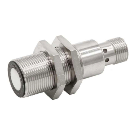
Ultrasonic Distance Sensor
Ultraschall Abstandssensor
Capteurs Ultrasoniques
MANUAL •Subject to alteration! Version: October 2004
ipf electronic gmbh
•Rosmarter Allee 14 •58762 Altena
│
Tel +49 2351 9365-0 •Fax +49 2351 9365-19
│
[email protected] •www.ipf-electronic.com 1
Wiring
Pin Function
1 24 Vdc
2 0 V GND
3 Output/ Ausgang/Sortie; 0 to 10 V
4 Switching output/Schaltausgang/ Sortie a seuil 1 (PNP)
5 Switching output/Schaltausgang/ Sortie a seuil 2 (PNP)
6 Hold / Synchronisation
7 RS232 RxD .. RS485-B
8 RS232 TxD .. RS485-A
1
2
3
4
5
6
8
7
View to solder pins of
connector/ Blick auf
Lötkontakte Kabelstecker
Vue sur les pins à soudée du
connecteur cable Dimensions/Abmessungen/Dimensions
Hold/synchronisation input Hold- und Synchronistaionseingang Entrée d’invalidation/synchronisation
If a measurement is only to take place in a certain
instant, the sensor transmit and receive can be
suppressed by a LOW (0V) at the hold HLD input.
The last calculated distance is stored and output.
During programming the HLD input should also
be connected with the HLD line.
If the sensor is enabled once more (HLD open or
HIGH), a new output occurs after completion of a
measurement cycle.
Synchronisation
To avoid mutual interference from several sensors,
these are very simply synchronised by
interconnecting the hold inputs.
Durch Verbinden von /HLD mit GND stellt der
Sensor den Sendebetrieb ein und speichert den
letzten Meßwert.
Synchronisation
Die Geräte der Serie 942 lassen sich
synchronisieren, indem die /HLD- Klemmen
miteinander verbunden werden. Hierbei werden
die Sendebefehle aller synchronisierten Geräte zur
gleichen Zeit ausgelöst. Diese Funktion
ermöglicht den Betrieb von mehreren Sensoren
sehr dicht beieinander ohne gegenseitige
Beeinflussung.
Si une mesure doit être faite seulement à un certain
moment, l’émission et la réception du capteur peuvent
être interrompues en mettant l’entrée d’invalidation
(broche 6) sur LOW
(0 V). La dernière valeur de distance calculée est
mémorisée et affichée à la sortie. Pendant la
programmation, l’entrée d’invalidation doit aussi être
connectée à la ligne d’invalidation.
Si le capteur est activé une fois de plus (HLD ouvert
ou HIGH), une nouvelle valeur apparait aprés la fin du
cycle de mesure.
Synchronisation
Pour éviter les interférences entre plusieurs capteurs,
on peut trés facilement les synchroniser en reliant leurs
entrées d’invalidation.
Programming/Programmierung/Programmation
Programming instruction
Set baudrate fix to 9600,N,8,2 (no parity bit, 8 data bits
and 2 stop bits).
Each command has the same structure: @aBp<CR>
@ Beginning of command, always identical
a Address of sensor; with '#' all sensors will
be addressed
B Command
p Parameter
<CR> End of command CR=ENTER=#13
A more simple way to program the sensor is the use of
the programs UDSE.EXE or SENDE.EXE available as
accs.
Programmierung
Die Baudrate ist fest auf 9600,N,8,2 (kein Paritätbit, 8
Daten- und 2 Stopbits
Alle Befehle haben den gleichen Aufbau: @aBp<CR>
mit:
@ Befehlseinleitung, immer gleich
a Adresse des Sensors, mit ‘#’ werden
alle Sensoren angesprochen.
B Befehl, immer in Großbuchstaben
p Parameter, immer eine Dezimalzahl im
ASCII Format
<CR>Ende des Befehls <CR>=ENTER=#13
Eine einfachere Art der Programmierung erfolgt mit den
Programmen UDSD.EXE und SENDD.EXE die als
Zubehör verfügbar sind.
Instructions de programmation
Fixer le baudrate à 9600,N,8,2 (pas de parité, 8 bits et 2 bits
d’arrêt).
Toutes commandes ont la meme structure
@aBp<CR> avec :
@ Début de commande , toujours identique
a Adresse du capteur; avec '#' adresse de
tous les capteurs
B Commande
p Paramètre
<CR> Fin de commande CR=ENTER=#13
L’utilisation des programmes UDSE.EXE ou SENDE.EXE
(disponibles comme accessoires) représente un moyen plus
simple de programmation des capteurs.
List of Commands/ Befehle:
@#I<CR> Load factory setting into RAM The initial
setting will be written from the EEPROM
into the ROM. Factory settings added to the
following commands are marked with a *
Grundeinstellung laden Hierbei gehen
die spezifischen Abgleich-Einstellungen
des Werksendtestes nicht verloren! Die
Werkseinstellungen sind im Folgenden
mit * gekennzeichnet.
Charger la configuration par défaut dans la
RAM La configuration par défaut sera
transmise de l’ EEPROM dans le ROM. Les
configurations par défaut ajoutées au
commandes suivantes sont marquées d’un a *.
@#W<CR> Write actual setting into the EEPROM Speichern der Einstellung Ecrire configuration utilisée dans le
EEPROM
@aAp<CR> @aA97* Change sensor address from A to ASC(Y) Ändern der Adresse von A auf ASC(Y) Changer l’adresse capteur de A vers ASC(Y)
@aSp<CR> 0≤p≤255 cm @aS200* Adjustment of the analogue output range Steigung des Analogausgang einstellen Régler la portée de la sortie analogique
@aOp<CR> 0≤p≤255 cm @aO0* Offset of the analogue output Offset des Analogausganges Offset de la sortie analogique
@a1p<CR> 0≤p≤10000mm @a500* Set point 1 Schaltpunkt 1 Seuil 1
@a2p<CR> 0≤p≤10000 mm @a1000* Set point 2 Schaltpunkt 2 Seuil 2
@aHp<CR> 0≤p≤255 mm @aH10 Hysteresis set point 1 Hysterese Schaltpunkt 1 Hystérésis seuil 1
@aGp<CR> 0≤p≤255 mm @aG10 Hysteresis set point 2 Hysterese Schaltpunkt 2 Hystérésis seuil 2
@aUp<CR> 0≤p≤255 cm @aU15* Under range adjustment Under-Range Einstellung Réglage de la zône de non détection
@aCp<CR> @aC32* Cycle time adjustment Messzyklus einstellen Réglage de la fréquence de cycle
@aXp<CR> 0≤p≤255 @aX238* Offset adjustment Offsetabgleich Réglage de l’offset
@aRp<CR> 0<p<256 @aR30* Over range counter Over-Range Austastung Compt. hors détection
@aTp<CR> 0≤p≤255 @aT52* Fail echo suppression counter Störunterdrückung Compt. de suppression de fausse impulsion
@aD<CR> Read out sensor setting Parametertabelle auslesen Lire la configuration du capteur
A<CR> Read out of one Distance Measurement Einzelne Meßwerte abrufen Lire la distance simple par RS interface
@aMp<CR> 0≤p≤255 @aM1* Mode Register Mode Register Registre de mode
Mode Register/ Registre de mode
Value of parameter p is between 0 and 255.
It is determined by combination of following bits. Der Wert des Parameter p liegt zwischen 0 und 255. Er wird
durch die Kombination folgender Bits bestimmt: La value du paramètre p est située entre 0 and 255. Elle
est déterminée par la combinaison des bits suivants :
Name. Bit Val. Function ( 1 ) Function ( 0 ) Funktion(1) Function ( 0 ) Fonction ( 1 ) Function ( 0 )
SET 7128 Switching output
window Normal switching Fensterfunktion Schaltausg. Normale Schaltfunktion Sorties à seuils fenêtre Fonction normale
SAO 664 Serial output disabled Serial output enable Serieller Ausgang
freigegeben Seriell. Ausgang
gesperrt Sortie série désactivée Sortie sér. activée
HFT* 532 Special triggering Echo Normal triggering Spezielle Echo- Auswertung Normale Auswertung Déclenchmnt spécial écho normal
INV 4 16 Neg. slope analog output Positive slope Neg. Kennlinie
Ana.ausgangs Positive Kennlinie Pente négative Pente positive
MWO 3 8 Output no mean value With mean value Keine Mittelwertbildung Mit Mittelwertbildung Sans valeur moyenne Avec moyenne
NC2 2 4 Switch 2 is NC Switch 2 is NO SP 2 hat NC Charakter NO Charakter Seuil 2 est NC Seuil 2 est NO
NC1 1 2 Switch 1 is NC Switch 1 is NO SP 1 hat NC Charakter NO Charakter Seuil 1 est NC Seuil 1 est NO
BCD 0 1 Digital output in BCD Digital output HEX Digitalausgang in BCD in HEX Sortie numérique en BCD en HEX
MANUAL •Subject to alteration! Version: October 2004
ipf electronic gmbh
•Rosmarter Allee 14 •58762 Altena
│
Tel +49 2351 9365-0 •Fax +49 2351 9365-19
│
[email protected] •www.ipf-electronic.com 2

Other ipf electronic Accessories manuals

ipf electronic UT139570 User manual

ipf electronic

ipf electronic UT139570 User manual

ipf electronic DW34312 Series User manual

ipf electronic

ipf electronic DW34312 Series User manual

ipf electronic OT450521 User manual

ipf electronic

ipf electronic OT450521 User manual

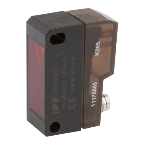
ipf electronic ON430570 User manual

ipf electronic

ipf electronic ON430570 User manual

ipf electronic OT0591A4 User manual

ipf electronic

ipf electronic OT0591A4 User manual

ipf electronic PT65 Series User manual

ipf electronic

ipf electronic PT65 Series User manual

ipf electronic PY740020 User manual

ipf electronic

ipf electronic PY740020 User manual

ipf electronic OTR49175 User manual

ipf electronic

ipf electronic OTR49175 User manual

ipf electronic UT300027 User manual

ipf electronic

ipf electronic UT300027 User manual

ipf electronic MW10015 Series User manual

ipf electronic

ipf electronic MW10015 Series User manual

ipf electronic DW35312 Series User manual

ipf electronic

ipf electronic DW35312 Series User manual

ipf electronic PRQ80376 User manual

ipf electronic

ipf electronic PRQ80376 User manual

ipf electronic OS15 Series User manual

ipf electronic

ipf electronic OS15 Series User manual

ipf electronic ON330571 User manual

ipf electronic

ipf electronic ON330571 User manual

ipf electronic UT360321 User manual

ipf electronic

ipf electronic UT360321 User manual

ipf electronic opti-check OC5396 Series User manual

ipf electronic

ipf electronic opti-check OC5396 Series User manual

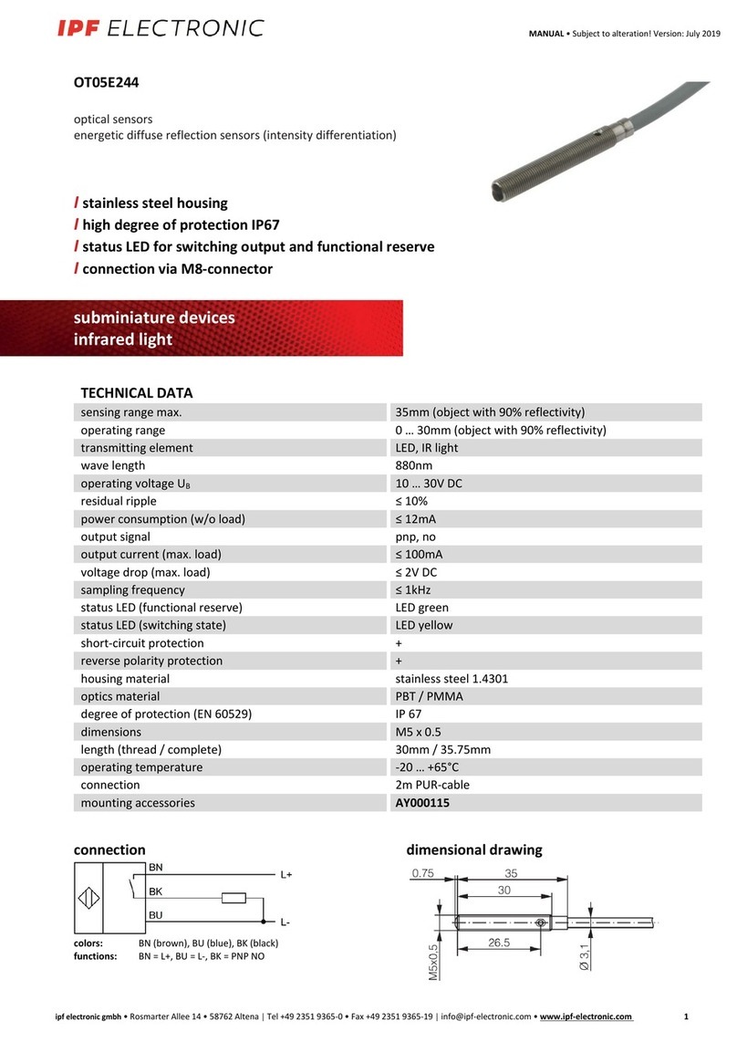
ipf electronic OT05E244 User manual

ipf electronic

ipf electronic OT05E244 User manual

ipf electronic OTR49170 User manual

ipf electronic

ipf electronic OTR49170 User manual

ipf electronic DW34311 Series User manual

ipf electronic

ipf electronic DW34311 Series User manual

ipf electronic UT189023 User manual

ipf electronic

ipf electronic UT189023 User manual

ipf electronic PT120320 User manual

ipf electronic

ipf electronic PT120320 User manual

ipf electronic UT139073 User manual

ipf electronic

ipf electronic UT139073 User manual

ipf electronic OTR49176 User manual

ipf electronic

ipf electronic OTR49176 User manual

ipf electronic UT30C310 User manual

ipf electronic

ipf electronic UT30C310 User manual

Popular Accessories manuals by other brands

echoflex RVS-A-XW installation guide

echoflex

echoflex RVS-A-XW installation guide

Visonic MCT-340 SMA installation guide

Visonic

Visonic MCT-340 SMA installation guide

brennenstuhl RCS 2044 N Comfort operating instructions

brennenstuhl

brennenstuhl RCS 2044 N Comfort operating instructions

Pyxis ST-772 user manual

Pyxis

Pyxis ST-772 user manual

WAMGROUP TOREX ILV Assembly instructions

WAMGROUP

WAMGROUP TOREX ILV Assembly instructions

Panasonic HG-S1010-AC instruction manual

Panasonic

Panasonic HG-S1010-AC instruction manual

Aukey PB-N65 user manual

Aukey

Aukey PB-N65 user manual

Eldes EWM1 V2 user guide

Eldes

Eldes EWM1 V2 user guide

LEDsec ST78-2 Instruction

LEDsec

LEDsec ST78-2 Instruction

Panasonic HL-G1-A-C5 Series user manual

Panasonic

Panasonic HL-G1-A-C5 Series user manual

Clas Ohlson HTD54010 manual

Clas Ohlson

Clas Ohlson HTD54010 manual

SICK MRS1000P operating instructions

SICK

SICK MRS1000P operating instructions

Xylem NitraVis 701 IQ TS operating manual

Xylem

Xylem NitraVis 701 IQ TS operating manual

Velleman PEREL EDP1 user manual

Velleman

Velleman PEREL EDP1 user manual

Ezetil E24 Operating and safety instructions

Ezetil

Ezetil E24 Operating and safety instructions

Chauvin Arnoux MiniFLEX user manual

Chauvin Arnoux

Chauvin Arnoux MiniFLEX user manual

Baumer UNAR 18P6903/S14G manual

Baumer

Baumer UNAR 18P6903/S14G manual

ring Contact Sensor 2nd Generation Z-Wave Technical manual

ring

ring Contact Sensor 2nd Generation Z-Wave Technical manual

manuals.online logo
manuals.online logoBrands
  • About & Mission
  • Contact us
  • Privacy Policy
  • Terms and Conditions

Copyright 2025 Manuals.Online. All Rights Reserved.