STEP 2: INSTALL THE ODU MOUNTING BRACKET
A suitable mounting plate (8) must be procured or fabricated in
order to mount the supplied mounting bracket to a pole or mast.
The mounting bracket supplied maybe used as a template for holes.
Recommended mounting using mounting bracket
Note: Neoprene bonded stainless steel washers are included to
protect the anti-corrosion coating on the stand and to prevent
galvanic corrosion of the assembly. 316 stainless steel installation
hardware is recommended.
Installer supplies item 4, 6, 7 and 8
1. Take care when transporting the radome (1) and stand (2)
so as not to damage the corrosion resistant coatings.
2.
Place an isolation gasket (3) onto the mounting post (8).
3. Place the stand (2) onto the isolation gasket, with the slotted
side facing down.
4. Slide a neoprene bonded isolation washer (5) onto an M10 hex
head bolt (4) , with its metal side contacting the bolt.
5. Slide this bolt assembly through the slot in the stand then through the hole
in the ship’s mounting post.
6. Slide on another isolation washer with the rubber side facing the mounting post.
7. Thread on a jam nut (6) finger tight.
8. Thread on a hex nut (7).
9. Repeat steps 4-8 for the remaining three bolts.
10. Tighten the jam nuts using 10-12 ft-lbs of torque.
11. For all four bolts: preventing the jam nut and bolt from turning, tighten the hex nut against
the jam nut until they lock, taking care not to overtighten.
Note: Prior to connecting the ODU/IDU cable, the RJ-45 connector must be grounded using strap wire/electrical
clips to the vessel ground (not an existing electrical system ground). This is required to prevent static discharge
when connecting to the system.
NOTICE: Install ground cables for both the ODU and IDU before using Pilot Land Station. Instructions on
how to install the ground cables are provided in the Installation Guide. Failure to properly ground the ODU
and the IDU could result in property damage in the case of a lightning strike or other excessive static
build-up.
WARNING
Damage to the paint coating may allow rust to the ODU which could result in failure of the ODU.
This in turn could cause disruption in operation of the Iridium Pilot Land Station device or danger
from a falling unit. Avoid damaging the paint coating. If damage occurs, re-apply appropriate
anti-corrosion paint. Failure to do so could result in serious injury or death.
WARNING
ODU must be properly mounted and secured at the install location. Failure to do so could result in
detachment of the unit, causing disruption in operation of the unit, or danger from a falling unit,
which could result in serious injury or death.
STEP 3: INSTALL THE ODU RADOME
Note: Grounding lug on radome base must be facing aft or “rear”
of install location. Orientation of this grounding lug is used in
diagnostic software as the “Aft” orientation of the antenna.
1. Place an isolation gasket (3) on top of the stand.
2. Route the power/data cable (not pictured) through
either the bottom of the stand or through its side
hole, up through the top hole in the stand. Plug
the cable into the connector on the bottom of the radome.
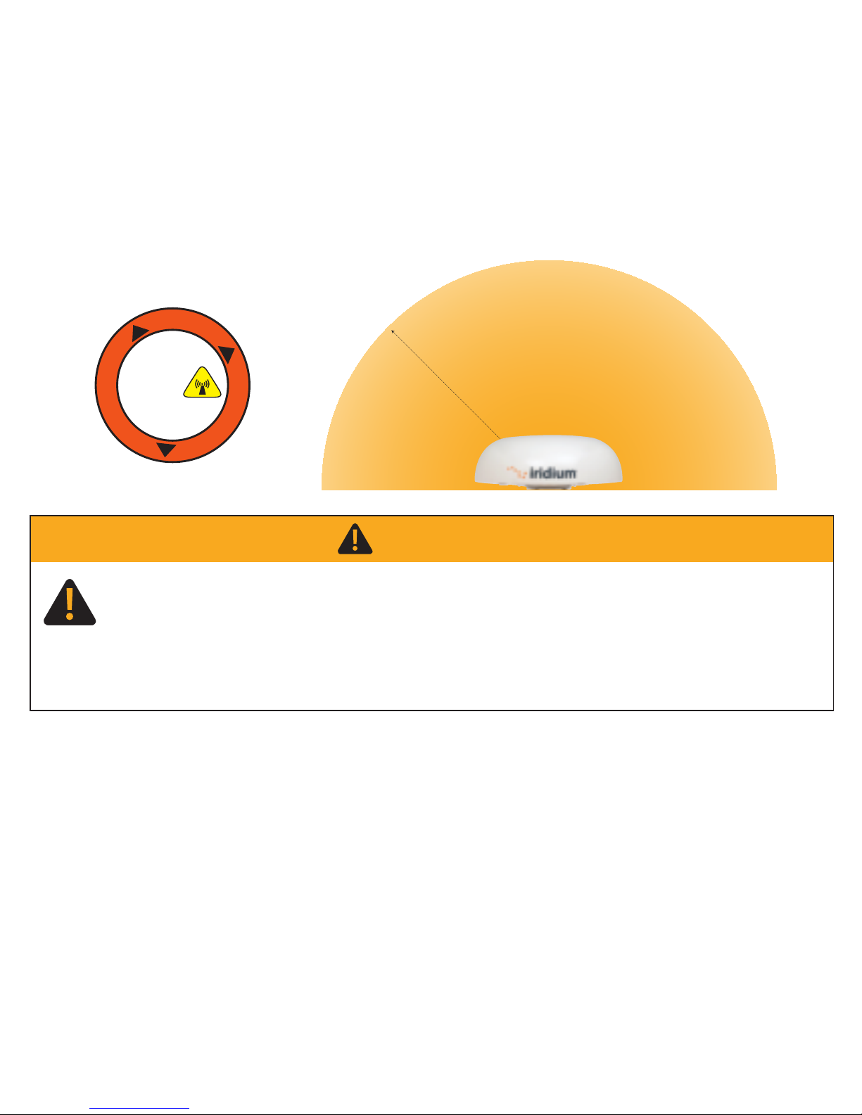
3. Place the radome onto the stand, with the arrow on the
base pointing toward the bow.
4. Slide a lock washer (9) then an isolation washer (5) onto
an M10x30 mm hex head bolt (10). The metal side of the isolation washer should face the lock
washer. Apply anti-seize compound (12, not pictured) to the bolt threads.
5. Slide the prepared bolt up through the stand, and finger tighten into the dome array.
6. Repeat steps 4 and 5 for the remaining three bolts.
7. Tighten the four bolts using 10-12 ft-lbs of torque.
8. Use the included grounding hardware kit to alter the length of the ground cable as needed. Attach
ground cable between two lock washers (9) on the 20 mm M10 bolt (11) and then place flat washer
(13)on the bolt prior to tightening on the ground post on the ODU. Torque bolt to 40 in/lbs. Attach the
terminating end of the ground cable to ground connection (non-electrical system ground) at the
location using a suitable clamp or terminal.
87804_TPQSG1301.indd 7 1/30/14 2:28 PM