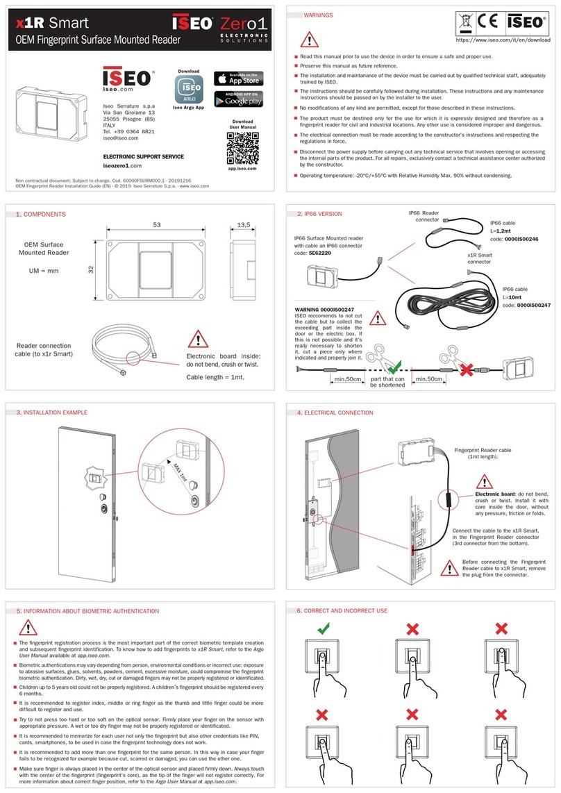
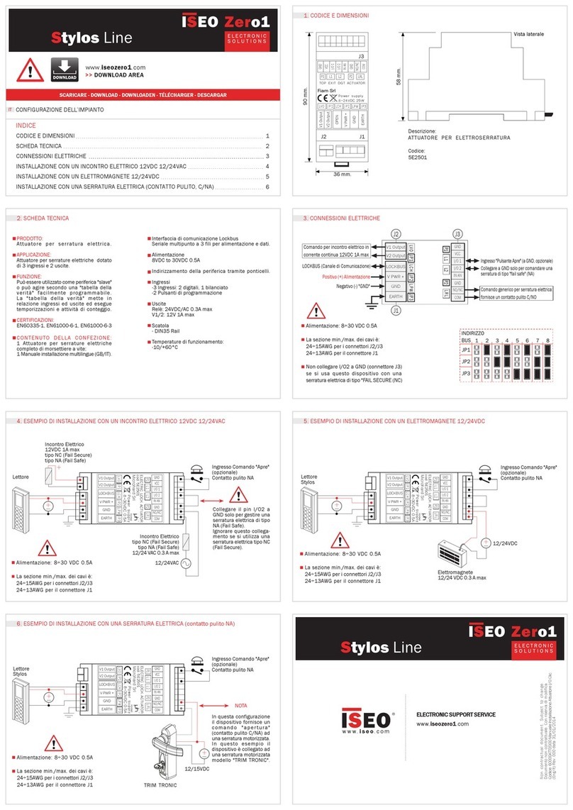
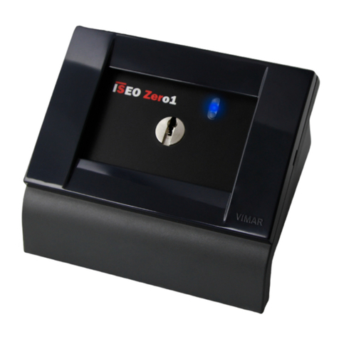
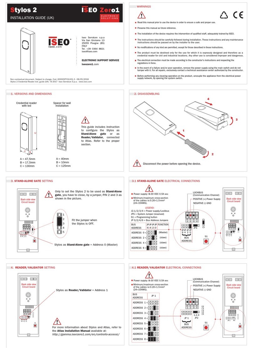
Iseo ZERO1 STYLOS LINE Series Quick guide

ACCESS CONTROL SYSTEM
STYLOS LINE SERIES
SYSTEM’S CONFIGURATION


How to use this manual
3
ACCESS CONTROL SYSTEM OF THE STYLOS LINE SERIES
How to use this manual
Thanks for choosing this innovative ISEO product.
This user manual was elaborated to offer instructions on configuring a SIMPLY STYLOS LINE system,
consisting of readers of the STYLOS series and LockBus actuators. All compatible products are indicated in
the table of compatible products with the SIMPLY STYLOS LINE system.
The configuration and changes to the system require the intervention of qualified staff, adequately
trained by ISEO.
Read this manual prior to proceed with the configuration in order to ensure the proper and safe operation
of the system.
Preserve this manual for future reference and for potential changes to the system or to replace
components.
Information icons
Please familiarise with the icons below, for an easy reading of the manual:
WARNING: it indicates situations that could cause harm to people or animals
BE CAREFUL: It indicates situations that could cause damages to the device or other apparatuses
NOTE: it indicates notes, suggestions and additional information
Information on copyright
The rights concerning all technologies and products which are part of this device, belong to the relative
holders.

SYSTEM’S CONFIGURATION Summary
4
ACCESS CONTROL SYSTEM OF THE STYLOS LINE SERIES
Summary
How to use this manual...................................................................................................................3
Information icons......................................................................................................................................................3
Information on copyright...........................................................................................................................................3
Summary.........................................................................................................................................4
Introduction .....................................................................................................................................5
Components compatible with the SIMPLY STYLOS LINE system...........................................................................5
Installation.......................................................................................................................................6
Preamble..................................................................................................................................................................6
Cabling of the LockBus ............................................................................................................................................6
Configuration of the addresses ................................................................................................................................6
Exchange of coded keys ..........................................................................................................................................7
Types of system..............................................................................................................................8
Configuration 1 reader 1 actuator.............................................................................................................................8
Configuration 2 readers 1 actuator...........................................................................................................................9
Configuration 4 readers 2 actuators with interlock function....................................................................................10
Replacement or addition of devices...............................................................................................11

Introduction
5
ACCESS CONTROL SYSTEM OF THE STYLOS LINE SERIES
Introduction
SIMPLY STYLOS LINE is an effective access control system, user-friendly and at the same time, powerful
and of high quality.
The SIMPLY STYLOS LINE system consists of Access Control Devices (ACD) and actuators, with which it is
possible to configure different system’s variants according to the type of door to control.
The system’s components communicate with each other through a LockBus network with coded security
communication protocol.
The scope of this manual is to describe the concepts relative to the devices’ configuration in a LockBus
communication network, based on the type of system’s door.
Components compatible with the SIMPLY STYLOS LINE system
READERS
ACTUATORS
For references relative to electric connections, location of the configuration jumpers and
programming keys, refer to the specific installation manuals contained inside the packages of the
devices.
The examples and the description of this manual refer to the names and numbers common for all
devices of the SIMPLY STYLOS LINE system. Follow the instructions herein and apply them to the
devices as indicated in the relative installation manuals.
The manuals are available also online, in the download area of ISEO Serrature’s website, at
http://www.iseoserrature.com.
PAD ACD
STANDARD ACD
DROP-BOLT
ACTUATOR FOR
ELECTRO-MECHANICAL
LOCKS

SYSTEM’S CONFIGURATION Installation
6
ACCESS CONTROL SYSTEM OF THE STYLOS LINE SERIES
Installation
Preamble
In the SIMPLY STYLOS LINE system, all the devices that make it up, readers and actuators, communicate
with each other through the coded LockBus protocol. The coding key is distributed by the device classified as
MASTER to all other SLAVE devices of the system, during the key exchange process in the installation or
editing phase.
The configuration process of the system or door must be performed following the sequence below:
Cabling of the LockBus (see installation manuals of the devices of the STYLOS LINE series)
Configuration of the addresses
Exchange of coded keys
Initialisation and configuration of the devices (see user manuals of the devices of the STYLOS LINE
series)
Cabling of the LockBus
Connect the following contacts of all door’s devices, in parallel:
SUPPLY POSITIVE POLE (+)
SUPPLY NEGATIVE POLE (GND)
LOCKBUS
Configuration of the addresses
Each door can consist of minimum 2 devices (a reader and an actuator) up to maximum 8 (4 readers and 4
actuators), each of which must be identified through a univocal address between 0 and 7.
Address 0 is attributed to the MASTER reader, an essential part of the system. If only one reader is present,
this is the MASTER reader, while if more readers are present, select one as MASTER reader (address 0) and
configure the others using addresses other than 0 (2, 4 or 6).
Even addresses are reserved to readers and odd addresses to actuators, as indicated in the table:
DEVICE
ADDRESS
MASTER READER
0
OTHER READERS
2 , 4 , 6
ACTUATORS
1 , 3 , 5 , 7
Configure the addresses on each device according to the selected type of door, assigning the addresses as
described in the configurations included in chapter Types of system.
Installation
7
ACCESS CONTROL SYSTEM OF THE STYLOS LINE SERIES
Exchange of coded keys
The LockBus protocol of the SIMPLY STYLOS LINE is coded to ensure the system’s security.
During the initialization or modification phase of the system, the MASTER device (address 0) must generate
and communicate the coded keys to all other SLAVE components (addresses from 1 to 7) of the system.
To exchange the keys, proceed as follows:
1. Disconnect the POWER/ LOCKBUS connector from all devices.
2. Put the actuators in ‘’Key exchange request'' mode, one by one: by pressing a programming button,
connect the SUPPLY/ LOCKBUS connector and wait at least one second prior to release the button.
3. Put the readers in ‘’Key exchange request'' mode, one by one, leaving the MASTER reader for last:
by pressing a programming button, connect the SUPPLY/ LOCKBUS connector and wait for the
acoustic signal prior to release the button.
4. After connecting the MASTER device, start to exchange keys. At the end of the operation, the
MASTER device emits 5 acoustic signals and the ISEO logo appears on the display if PAD ACD, or
the fixed blue lights in case of Standard ACD.
Should point 4 not be successful, repeat the procedure from point 1.
5. The exchange of keys has been completed, the system’s mapping has been created and remains
unaltered until the following key exchange, required only to replace or add devices.
In any case, do not keep the programming button pressed for over 2/3 seconds.

SYSTEM’S CONFIGURATION Types of system
8
ACCESS CONTROL SYSTEM OF THE STYLOS LINE SERIES
Types of system
This section includes some examples of systems and the relative address configurations. For the physical
configuration procedure, refer to the installation manual contained in the device's packaging.
The LockBus protocol of the SIMPLY STYLOS LINE series is designed so that the readers with address 0
and 2 control the actuators with addresses 1 and 5, while the readers with address 4 and 6 control the
actuators with address 3 and 7.
For the proper operation of the system, follow the configurations of the devices’ addresses described
in the examples.
Configuration 1 reader 1 actuator
It is the basic configuration of the door, with electronic opening from a single point, consisting of a reader #0
(MASTER address: 0) and an actuator #1 (address: 1).
READER
ACTUATOR
ADDRESS
0
1
TYPE
PAD ACD or
STANDARD ACD
DROP-BOLT
OR ACTUATOR
LockBus

Types of system
9
ACCESS CONTROL SYSTEM OF THE STYLOS LINE SERIES
Configuration 2 readers 1 actuator
In this configuration, the door can be opened from two points and the system consists of a reader #0
(MASTER address: 0), a reader #2 (address: 2) and an actuator #1 (address: 1).
READER
ACTUATOR
READER
ADDRESS
0
1
2
TYPE
PAD ACD or
STANDARD ACD
DROP-BOLT
OR ACTUATOR
PAD ACD or
STANDARD ACD
LockBus

SYSTEM’S CONFIGURATION Types of system
10
ACCESS CONTROL SYSTEM OF THE STYLOS LINE SERIES
Configuration 4 readers 2 actuators with interlock function
This example of application shows a configuration extended to 2 doors, in which a reader #0 (MASTER
address: 0), and reader #2 (address: 2) of the first door send the opening command and receive the status of
the first door from actuator #1 (address: 1), while readers #4 (address: 4) and #6 (address: 6) send the
opening command and receive the status of the second door from actuator #3 (address: 3).
If the system is configured with manual or automatic interlock, a door can be opened only if the other one is
closed. The MASTER device manages the statuses through LockBus communication. In this case, the
actuators’ addresses must be compulsorily 1 and 3.
In the drop-bolt manual, refer only to the address configuration page (setting them at 1 and 3
respectively) and not to the configuration page of the interlocked system, since this is valid only for
connection without the STYLOS LINE readers.
FIRST DOOR
SECOND DOOR
READER
ACTUATOR
READER
READER
ACTUATOR
READER
ADDRESS
0
1
2
4
3
6
TYPE
PAD ACD or
STANDARD ACD
DROP-BOLT
PAD ACD or
STANDARD ACD
PAD ACD or
STANDARD ACD
DROP-BOLT
PAD ACD or
STANDARD ACD
LockBus

Replacement or addition of devices
11
ACCESS CONTROL SYSTEM OF THE STYLOS LINE SERIES
Replacement or addition of devices
The security of the SIMPLY STYLOS LINE system is guaranteed by the coded transmission and exchange of
coded keys, programmed during the mapping phase.
No other device can communicate with the system, if the key exchange did not take place.
For this reason, the replacement or addition of new devices to the system requires a new mapping between
devices, also pre-existing ones, for which a new key will be created.
To add or replace a device to the system’s LockBus, whether reader or actuator, make sure to configure the
appropriate address as described in chapter Address configuration and repeat the procedure described in
chapter Exchange of coded keys.
If the Coded key exchange procedure is not repeated, the new added or replaced device will not
communicate with the other devices and therefore it will not work properly.
This manual suits for next models
1
Table of contents
Other Iseo IP Access Controllers manuals

Iseo
Iseo Stylos 2 Operating and maintenance instructions

Iseo
Iseo Zero1 x1R Smart User manual

Iseo
Iseo Zero1 x1R Smart User manual

Iseo
Iseo STYLOS User manual

Iseo
Iseo Zero1 Stylos Instruction sheet

Iseo
Iseo Zero1 x1R Smart User manual

Iseo
Iseo Zero1 F9000 User manual

Iseo
Iseo Zero1 Libra Smart User manual

Iseo
Iseo 1NCA Mullion User manual

Iseo
Iseo Zero1 x1R Smart User manual