ENGLISH
2
Structure of Advanced soldering stations
system
The Advanced series has basic modules giving
you full flexibility for choosing what you need for
the work in hand, the modules being supplied
separately.
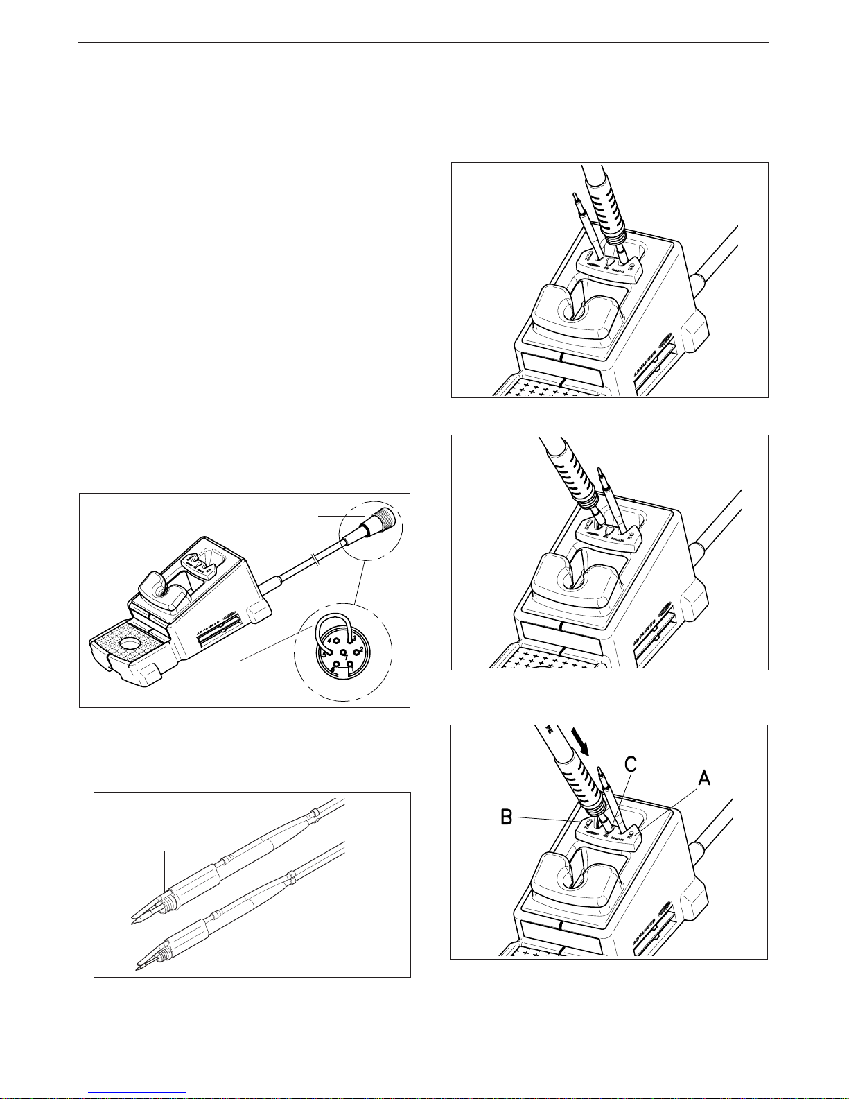
Dual control unit
-AD 4200 EU Ref.4200200
-AD 4200 UK Ref.4200201
Model AD 4200 can be used with two tools
simultaneous, either handpieces or desoldering
tweezers. Can be used with either combination of
2010, 2210,2045 and 2245 handpieces and the hot
tweezers PA 1200 or PA4200.
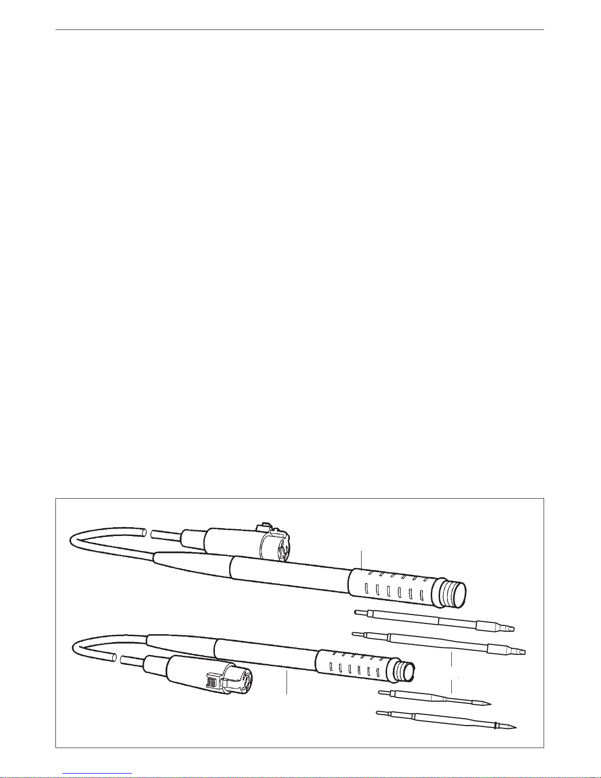
Handpieces
-2010 Ref.2010000
Power: 20W. For high precision work, SMD, etc.
-2210 Ref.2210000
Power: 20W. For high precision work, SMD, etc.
-2045 Ref.2045000
Power: 50W. For general soldering work.
-2245 Ref.2245000
Power: 50W. For general soldering work.
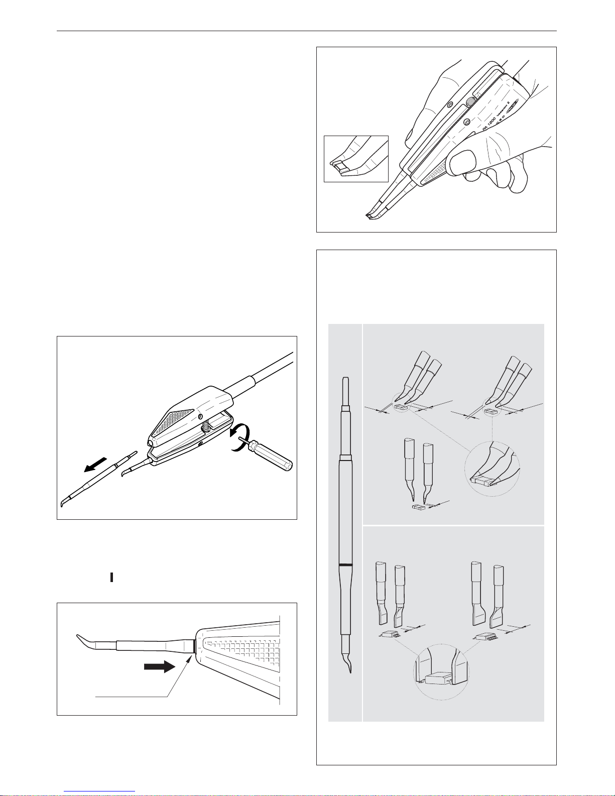
Hottweezers
-PA 1200 Ref.1200000
For general precision desoldering with SMD
components.
Power:40W.
Effective power per cartridge fitted: 20W.
-PA 4200 Ref.4200000
For general desoldering and soldering work in
professional electronics.
Power:100W.
Effective power per cartridge fitted: 50W.
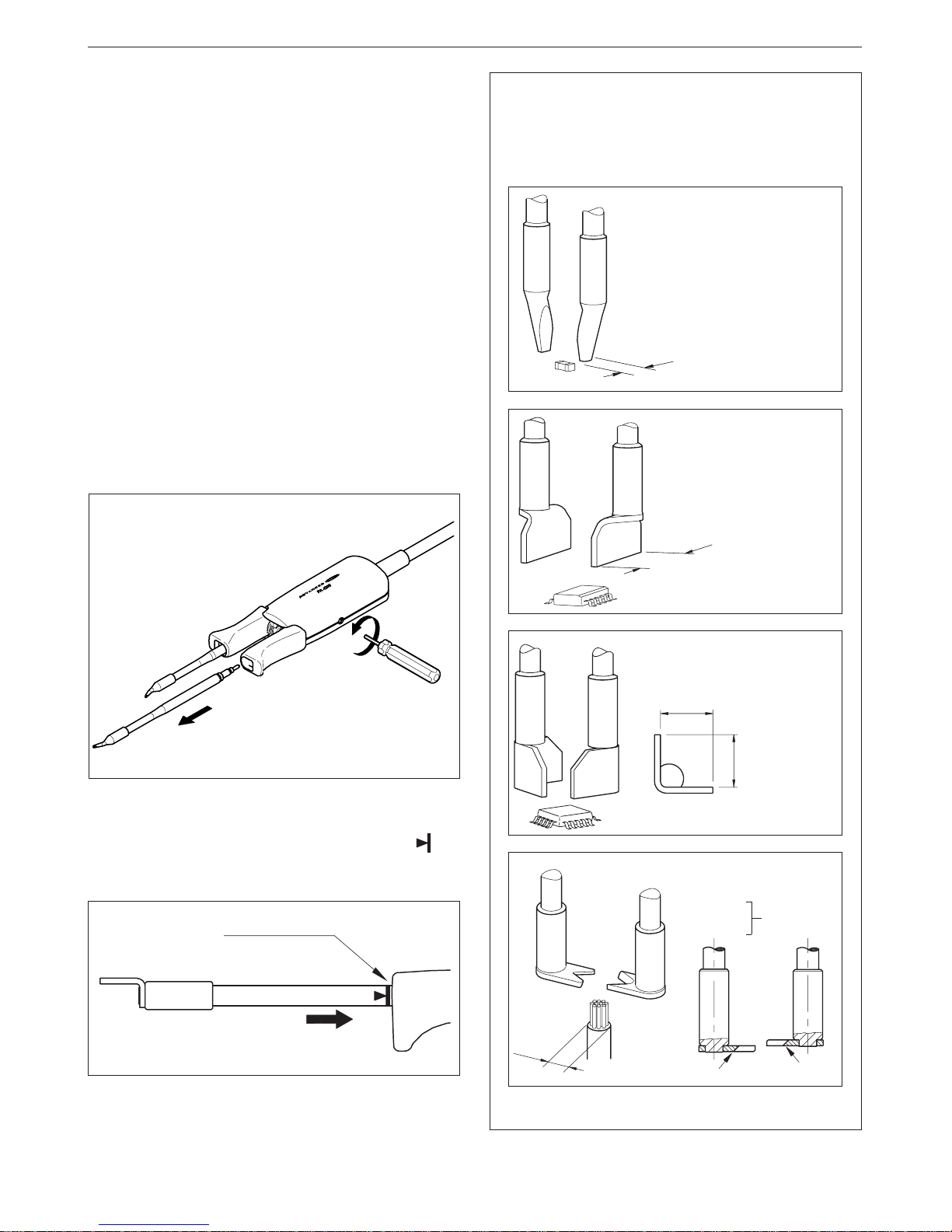
Cartridges
-Rangeofcartridges2010 (forthe2010 handpiece).
-Rangeofcartridges2210 (forthe2210 handpiece).
-Rangeofcartridges2045 (forthe2045 handpiece).
-Rangeofcartridges2245 (forthe2245 handpiece).
-RangeofcartridgesformicrohottweezersPA 1200.
-Range of cartridges for hot tweezers PA 4200.
Stands
-Soldering iron stand AD 8200 Ref.0268200
-PA 8420 Ref.0748420
Stand for the hot tweezers PA 4200.
-PA 8100 Ref.0748100
Stand for the hot tweezers PA 1200 and PA 4200.
For a dual soldering station work properly is
necessary: the dual control unit, a handpiece or the
hot tweezers, and the corresponding stand and
cartridge.
Dual control unit AD 4200
The station is supplied with:
-Control unit.
-Connection cable to mains.
-Instructions manual.
-Transport packaging.
Technical specifications
-Temperature selection from 100 to 371°C (±5%).
-Power: 135W.
-Safety transformer, mains separator and double
isolation, with integrated fuse of temperature
protection.
-Input: 230V 50Hz. Output: 24V.
-Electrical protection Class I.
-Total weight of unit: 5Kg.
-ESD protected housing.
Typical surface resistance: 105-1011Ohms/
square.
-Complies with CE standards on electrical safety,
electromagnetic compatibility and antistatic
protection.
-Equipotential connector is earth connected to the
plug feed of the station.
RECOMMENDATIONS FOR USE
For soldering and desoldering
-Clean the contacts and the printed circuit to
be desoldered of dust or dirt.
-Preferably select a temperature below 350°C.
Excess temperature may cause the printed
circuit tracks to break loose.
-The tip must be well tinned for good heat
conduction. If it has been inoperative for any
length of time, it should be retinned.