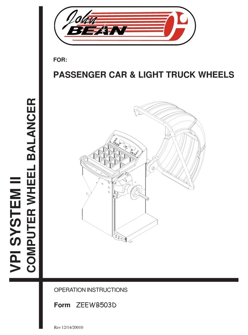
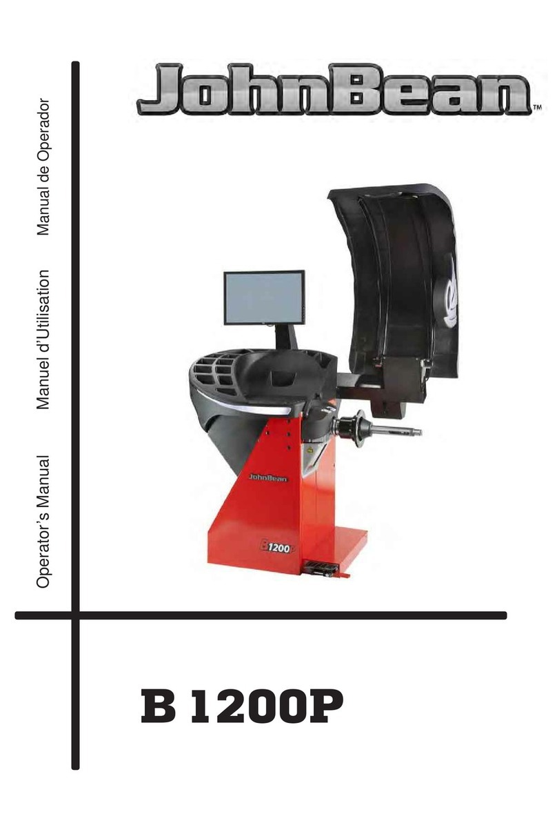
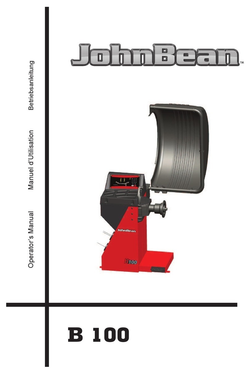
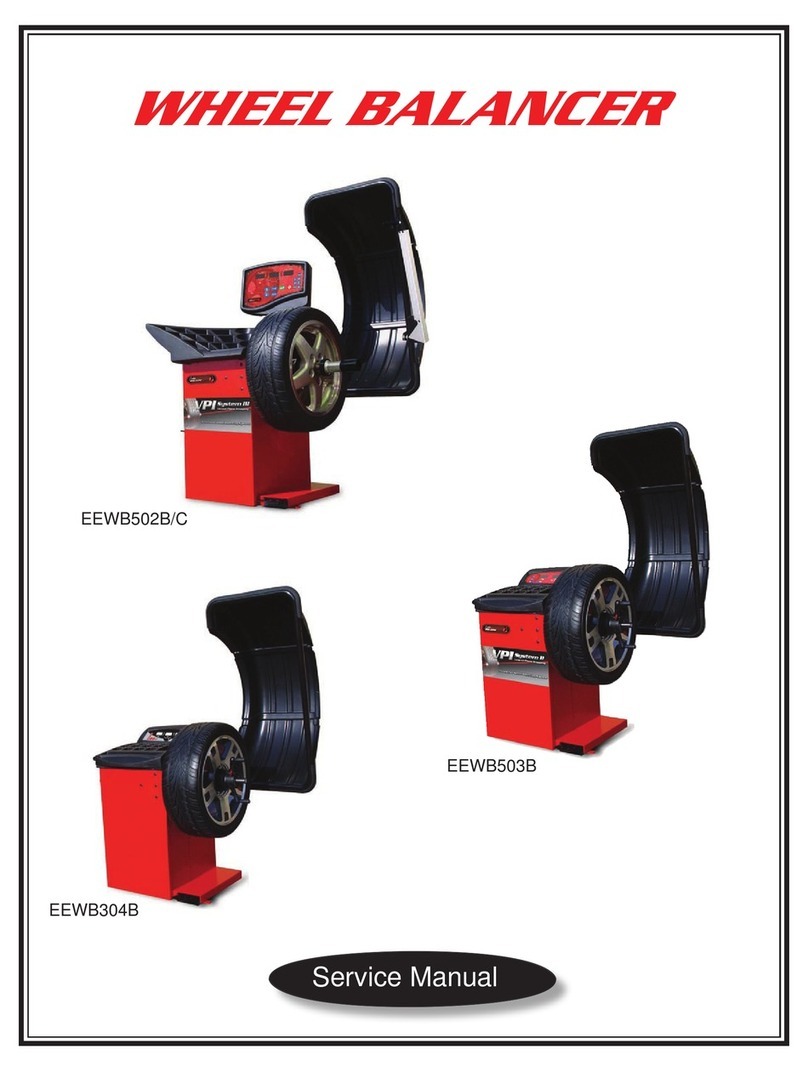
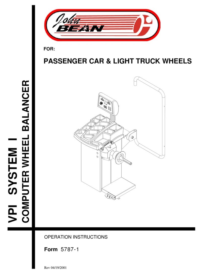
John Bean VPI System IV User manual

OPERATION INSTRUCTIONS
Form ZEEWB516A
5872
VPI SYSTEM IV
COMPUTER WHEEL BALANCER

Operator’s Manual
Table of Contents.
1 Safety. ..................................................................................................................................... 5
1.1 Typography. ......................................................................................................................... 5
2 Specifications. ........................................................................................................................ 6
2.1 Conditions. .......................................................................................................................... 6
3 Introduction. ........................................................................................................................... 8
3.1 Accessories. ...................................................................................................................... 10
4 Layout. ................................................................................................................................. 12
4.1 The Screen......................................................................................................................... 12
4.1.1 Pictographs - Symbols .................................................................................................... 13
4.1.2 Menu Fields..................................................................................................................... 17
4.1.2.1 Optimization / Weight Minimization .............................................................................. 20
4.1.3 Help Information .............................................................................................................. 21
4.1.4 Main Shaft Lock .............................................................................................................. 21
5 Operation. ............................................................................................................................ 32
5.1 Mounting The Wheel. ........................................................................................................32
5.1.1 Wheel Mounting Errors................................................................................................... 33
5.1.2 Wheel Rotational Errors. ................................................................................................ 34
5.1.3 Removal Of The Wheel. ................................................................................................. 34
5.2 Preparation........................................................................................................................ 38
5.2.1 Power Up ....................................................................................................................... 38
5.2.2 Emergency Stop............................................................................................................. 40
5.2.3 Shutting Down ................................................................................................................ 40
5.2.4 Settings .......................................................................................................................... 41
5.3 Balancing Procedure .......................................................................................................... 46
5.3.1 Input Of Wheel Type .......................................................................................................46
5.3.2 Input Of Balancing Mode................................................................................................. 47
5.3.3 Input Of Rim Dimensions For The Standard Balancing Mode ........................................ 48
5.3.3.1 Determination And Input Of Rim Width ........................................................................ 49
5.3.3.2 Gauge Head Application On Various Wheel Types ..................................................... 49
5.3.3.3 Determination Of Distance And Diameter .................................................................... 50
5.3.3.4 Determination And Input Of Wheel Diameter ............................................................... 51
5.3.3.5 Determining The Position Of The Hidden Weights (Alu 2s) ......................................... 52
5.3.3.6 Determining The Position Of The Hidden Weight (Alu 3s) ........................................... 53
5.3.3.7 Input Of Rim Dimensions For Display Of Static Unbalance ......................................... 55
5.3.3.8 Store Wheel Profiles ....................................................................................................55
5.3.4 Correction Of Inputs After Measurement......................................................................... 56
5.3.5 Observation Of Radial And Lateral Run-out Of The Wheels ........................................... 56
5.4 Spinning The Wheel ........................................................................................................... 70
5.4.1 Measurement .................................................................................................................. 70
5.4.2 How To Fit The Balance Weights .................................................................................... 71
5.4.2.1 How To Fit Balance Clips ............................................................................................. 71
5.4.2.2 How To Fit Adhesive Weights Using The Gauge Head ............................................... 72
5.4.2.3 How To Fit Adhesive Weights Based On Given Dimensions ....................................... 72
5.4.3 Check Run ...................................................................................................................... 73
Operator’s Manual
5.4.4 Static Unbalance ............................................................................................................ 73
5.5. Special Functions ............................................................................................................. 80
5.5.1 Behind-the-spokes Placement ....................................................................................... 80
5.5.2 Correction Of Measured Unbalance ............................................................................... 81
5.5.3 Changing Modes Of Operation....................................................................................... 83
5.5.3.1 List Of Modes Of Operation......................................................................................... 84
5.5.3.2 Counters...................................................................................................................... 86
5.5.3.3 Input Of Promotional Text ........................................................................................... 86
5.5.4 Optimization/ Weight Minimization ................................................................................. 88
5.5.4.1 General ....................................................................................................................... 88
5.5.4.2 Optimization/ Weight Minimization Programs .............................................................. 88
5.5.4.3 Start Optimization/Weight Minimization....................................................................... 89
5.5.4.4 Start Optimization........................................................................................................ 89
5.5.4.5 Continue Minimization And Optimization..................................................................... 90
5.5.5 Performing A Compensation Run................................................................................... 93
6 Maintenance...................................................................................................................... 108
6.1 Storage........................................................................................................................... 108
6.2 Changing The Mains Fuse. ............................................................................................ 108
6.3 Calibration Procedure..................................................................................................... 110
7 Trouble Shooting. .............................................................................................................. 114
7.1 System Messages. ......................................................................................................... 118
7.1.1. Error Codes ................................................................................................................. 118
7.1.2 C-codes. ...................................................................................................................... 122
8 Disposal. ........................................................................................................................... 128
9 Appendices. ...................................................................................................................... 128

4
1-1

5
Safety
Operator’s Manual
1 Safety.
All Safety Precautions relevant to the unit are described
in the Safety Booklet, refer to Figure 1-1.
The Safety Precautions should be fully understood by
every operator. We suggest to store (a copy) of the
Safety Booklet near the unit, in sight of the operator.
The Operator’s Manual will contain specific warnings
and cautions when possible dangerous situations may
be encountered during the described procedures.
1.1 Typography.
This manual contains text styles that asks you to pay
extra attention:
Note: Suggestion or explaination.
CAUTION: STRESSES THAT THE FOLLOWING
ACTION MAY CAUSE DAMAGE TO THE UNIT OR
OBJECTS ATTACHED TO IT.
WARNING: STRESSES THAT THE FOLLOWING
ACTION MAY CAUSE (SEVERE) INJURY TO THE
OPERATOR OR OTHERS.
•Bulleted list:
•indicates that action must be taken by the operator
before being able to enter the next step in the
sequence.

6
Specifications
Operator’s Manual
2 Specifications.
Power:
Power Supply
Motor rating
Power consumption
Mains fuses
Protection class
Measurements:
Measuring time
Measuring speed
Offset
Increments:
inch (<10”)
mm (PAX)
Wheel dimensions:
Max. width
Max. diameter
Max. weight
Rim width
Rim diameter:
NORMAL, ALU, STATIC
HWM1 / PAX
HWM2
Shaft and cones:
Stub shaft diameter
Cone, small
Cone, medium
Cone, large
Dimensions:
Weight
Shipping weight
Dimensions (hxdxw)
Shipping dimensions
Miscellaneous:
Noise level
2.1 Conditions.
During use or long term storage, the conditions should
never exeed:
Temperature range 0-50 °C
Humidity range 10-90 %, non condensing
230 V~, 50/60 Hz, 1 ph
0.12 kW
1.1 A
2x IEC 127 T5A
IP54
>3 s
<200 rpm
0-400 mm
0.5 (.25) ”
1mm
530 mm
950 mm
70 kg
25-510 / 1-20 mm/”
205-610 / 8-24 mm/”
215-610 / 8.5-24 mm/”
305-610 / 12-24 mm/”
40-28,5 mm
43-77 mm
74-100 mm
96-116 mm
137 kg
165 kg
1770x1175x1213 mm
1200x1020x1120 mm
< 70 db(A)

8
Introduction
Operator’s Manual
3 Introduction.
This wheel balancer combines advanced, high-
performance technology, robustness and reliability with
very simple, user-friendly operation.
The low rotation speed of the wheel ensures that this
balancer is very safe.
It features an easy-to-use display and input panel,
ensuring fast and intuitive operation.
Operator time and effort are reduced to a minimum,
while maintaining accuracy and consistancy.
Always work in a clean area and with clean wheels, no
dirt stuck in the tyre or on the rim. That way a proper
mounting of the wheel and an optimal balancing result
can be reached.
Application.
The off-the-vehicle wheel balancer is designed for
dynamic and static balancing of passenger car and
light-truck wheels, that fall within the limits stated in
the technical specifications.
This is a high accuracy measuring device. Handle with
care.
Manuals to the unit.
The setup of the information related to the unit is:
- Safety Booklet (standard supplement)
Supplied with the unit.
- Operator’s Manual (Chapter 1 – 9)
The operator must be familiar with it.
- Service Manual (Chapter 10 and up)
Manual for use by service personnel only.
Installation instructions.
The Installation Instructions can be found in Chapter
9, Appendices.

8
Introduction
Operator’s Manual
3.1-1
3.1 Accessories.
Refer to Figure 3.1-1.
The standard accessories are:
Quick-Release Hub Nut
Spacer ring
Universal drum
Universal drum cushion
Large cone
Medium cone
Small cone
Stub shaft
Key
User Calibration weight
Weight pliers
Callipers
4027007
0026425
0026426
0026427
0025539
0025518
0025517
0025516
4025821
0025415
0006452
4007580

12
4-1
4.1-1
4-2
4 Layout.
Refer to Figure 4-1.
Functional description of the unit:
1. The screen
Refer to Chapter 4.1.
2. Input panel
Refer to Chapter 4.2.
3. Gauge arm
The gauge arm is a multi-functional tool for
measurement and to apply weights.
4. Flange (hidden by wheel)
5. Stub shaft with quick release hub nut
6. Brake pedal
7. Weight compartments
8. Storage areas for cones or clamping devices
9. Tilting frame and hood
Hood may be optional.
Refer to Figure 4-2.
1. Mains switch (ON/OFF)
4.1 The screen
Fig. 4.1-1 Screen with display fields
1-5 Information fields
6Menu fields of screen
7Display field of screen
The screen reads out inputs, helpful information, all
measured
data and error codes.
Description of display fields
The screen is subdivided into various display fields,
each of
which is associated with a certain type of information.
Information fields
1 Number of the installed program version
Machine name
Date and time
2 Menu name
3 Selected wheel profile
4 Electrical compensation
5 Error codes
1 3
8
5
6
4
3a
7
9
2

13
4.1-2
P1
P2 P3
P4
4.1.1 Pictographs - Symbols
Pictographs are viewed on the screen in all fields: In
Information fields, menu fields, and in the display field.
P1 Wheel type standard
P2 Wheel type 1, -standard-, nominal size in inches
P3 Wheel type 3, -special wheel-, actual correction
dimensions, no nominal size. Motorcycles Program.
P4 Wheel type 2, -standard-, nominal size in mm
6 Menu fields
Pictographs illustrating special features are viewed
in the
six menu fields. Under every menu field is the
associated
menu key which is used to call the feature illustrated.
7 Display field
- Wheel type and rim dimensions
- Balancing modes
- Direction of orientation and correction position
(location of unbalance)
-Amount of unbalance
Fig. 4.1-2 Initial screen/Main menu

14
P9
P14 P15
P16 P17
P12 P13
P18 P19
P20 P21
P9 Standard rim
Balancing modes
P12 nor. - Standard balancing mode
P13 Alu 1
P14 Alu 2, Alu 2P
P15 Alu 3, Alu 3P
P16 Alu 4
P17 Alu 5
P20 Gauge arm for distance and rim diameter
P21 Gauge arm for distance and rim diameter with
adhesive weight

15
P22 P23
P24
P25
P26
P27 P28
P29 P30
P21a
P21a Gauge arm for rim width.
P22 Display of unbalance measured and direction
indicator (red arrows or arrow heads)
P23 Correction position reached (green arrows)
P24 Correction position for both correction planes
reached
P25 Compensation run carried out
P26 Start measuring run by pressing the START key
after closing the wheel guard.
P27 Calibration weight
P28 Main shaft
P29 Select memory location for wheel profile (red
arrow)
P30 Select a previously stored wheel profile (green
arrow)
70g0g

16
P31 P32
P33
P35 P36
P37 P38
P39
P34
P31 Provide mark on left tire side
P32 Provide mark on right tire side
P33 Fit tire on rim and inflate to the specified inflation
pressure
P34 Turn tire over on rim
P35 Rotate rim until valve is exactly perpendicular to
and above the main shaft
P36 Rotate wheel until valve is exactly perpendicular
to and above the main shaft
P37 Readjust tire on rim until the mark coincides
precisely with the valve
P38 Readjust tire on rim until the double mark coincides
precisely with the valve
P39 Tire changer

17
4.2-1
adbc
ef
T1 T2
T3 T4
T5
4.1.2 Menu fields
Types of menu fields
The assignment of the menu keys F1 to F6 is shown
in the menu fields above the relative keys on the
screen. The menu keys have different functions and
initiate different actions, depending on the program
step.
- Keys without a symbol in the upper right-hand
corner or at the edge initiate an action
immediately, e.g. key T2 Carry out compensation
run.
- Keys with one or more symbols in the upper right-
hand corner of the menu field or at the edges
initiate various actions:
aPress key to access a sub-menu, e.g. key T4
Balancing.
bPress and hold key down while rotating wheel at
same time, e.g. key T11 Number of spokes.
cPress key to toggle between two options or states,
e.g. key T9 Static / dynamic unbalance.
dPress key to toggle between several options or
states, e.g. key T21 Weight position for left correction
plane.
eToggle switch (4 functions): Press edge of key to
carry out the highlighted action, e.g. key T32
Character set: move the cursor in the character set
to the left, to the right, up or down.
fToggle switch (2 functions): Press key on top or
bottom to select the highlighted function, e.g. key
T8 Precision reading of unbalance.
Main menu
T1 Change to the screen FUNCTION
T2 Carry out compensation run
T3 Compensation run carried out
T4 Change to the screen BALANCING
T5 Change to the screen OPTIMIZATION MENU

18
T7 T8
T9
T11 T12
T10
T13 T14
T15 T16
T17 T18
BALANCING
T7 Change to menu RIM DATA INPUT
T8 Toggle switch, two functions; reading only as long
as the key is pressed (quick reading):
Pressed on top:
Precision reading of unbalance, no
suppression of minor unbalance readings.
Pressed on bottom:
Reading of amount and location of
unbalance for conventional balancing run
with balance clips - comes up.
T9 Select static unbalance
T10 Select dynamic unbalance
T11 Select number of spokes
T12 Wheel with 6 spokes selected
T13 Select behind-the-spokes placement mode
T14 Behind-the-spokes placement mode selected
RIM DATA INPUT
T15 Change to the screen WEIGHT PLACEMENT
T16 Change to the screen RIM TYPE
T17 Hold key down and enter the distance rim/machine
by rotating the wheel
T18 Hold key down and enter the rim width by rotating
the wheel

19
T19 T20
T21
T23 T24
T22
T25 T26
T27 T28
T29 T30
T19 Hold key down and enter rim diameter by rotating
the wheel
T20 Change to the screen PROFILE
WEIGHT PLACEMENT
T21 Select weight position for left correction plane
T22 Select weight position for right correction plane
FUNCTION
T23 Change to the screen USER CALIBRATION
T24 Change to the screen TEXT EDITOR
T25 Hold key down and set the value for the mode of
operation by rotating the wheel
T26 Hold key down and select the mode of operation
by rotating the wheel.
PROFILE
T27 Confirm wheel profile to be saved or selected
T28 Select stored wheel profile
T29 Store wheel profile
T30 Load previously stored profile

20
T31 T32
T33
T35 T36
T34
T37 T38
TEXT EDITOR
T31 Save text
T32Toggle key, four functions: Move the cursor within
the character set (right, left, up, down)
T33 Transfer characters from the character set to the
text field
T34Toggle key, four functions: Move the cursor within
the text field (right, left, up, down)
OPTIMIZATION / WEIGHT MINIMIZATION
T35 Continue interrupted optimization
T36 Start MINIMIZATION.
T37 Confirm
T38 Back

21
4.1.3-1
4.1.3-2
4.1.3-3
4.1.4-1
4.1.3 Help information
Help information explains the current action and, in
the case of
an error code, provides hints for remedy.
Display help information
•Press the HELP key (1 Fig. 4.1.3-1)
The first screen with help information appears, e. g. to
the
screen RIM DATA INPUT (Fig. 4.1.3-2).
•Press the HELP key once more to display the next
screen with help information.
The second screen with help information to the screen
RIM
DATA INPUT (Fig. 4.1.3-3) appears.
Note:
On pressing the HELP key in the last screen with help
information the display jumps to the first screen again.
Quit help information
•Press the ESC key (2 Fig. 4.1.3-1).
4.1.4 Main shaft lock
Fig. 4.1.4-1 Pedal of main shaft lock
The main shaft is locked when the pedal is depressed.
This facilitates tightening or untightening of the
clamping nut and retains the wheel in the correction
position for correct fitting of the balance weights.
This lock is designed only to facilitate orientation of
the wheel and must not be used for braking the main
shaft.

32
5.1-1
5 Operation.
This chapter describes how to operate the unit in order
to balance a wheel.
The standard balancing runs will be described first. In
chapter 5.4 and up special modes and functions will
be described.
Be sure to be familiar with:
- possible dangers, refer to chapter 1
- the unit, refer to chapter 4.
5.1 Mounting the wheel.
•Clean the wheel thoroughly prior to mounting it to
the unit.
•No dirt (sand, stones, glass, stickers, etc.) should
be left on the rim or the tyre.
•Remove all weights from the rim.
•Always balance a “clean” wheel!
•Work safely. Wear safety glasses.
Use only clamping and centring devices that fit properly
on the unit and are designed to be used with it. In order
to keep pace with technical progress, the unit, clamping
and centring devices may undergo design revisions.
Always check for compatibility between the devices and
the unit. Refer to the supplied technical information.
The method used to mount a wheel depends on the
way the wheel is centered at the vehicle.
- When the rim has a true center hole, a hub centric
wheel, use a cone. Refer to Figure 5.1-1, top. This
is also the faster way to mount a wheel. If the correct
cone is not available, or if a wheel is very hard to
balance, using an adaptor plate may help.
- When the rim does not have a true hole and should
be centered on the mounting studs, a lug centric
wheel, use an adaptor plate. Refer to Figure 5.1-1,
bottom.
Cone Mounting
Cone mounting is the most common way to mount
automobile wheels. Choose the cone that fits best when
placed through the wheel center hole. Place the cone
and wheel on the shaft and ensure that the cone centres
the wheel when you tighten the handle.
•Hold the handle in place and rotate the wheel when
tightening.
WARNING: ENSURE THAT THE WHEEL IS FIRMLY
AGAINST THE MOUNTING FLANGE AND THE
HANDLE THREADS ENGAGE AT LEAST THREE
TURNS ON THE SHAFT.

33
5.1-2
5.1-3
•Fit the supplied cushion to the pressure drum to
prevent damage to painted or non-steel rims.
Refer to Figure 5.1-2. From top to bottom the following
cone clamping systems are shown:
Back Cone Mounting with pressure drum.
The cone centers the wheel from inside. The
pressure drum should contact the wheel on a flat
surface. Never center the wheel with the pressure
drum.
Back Cone Mounting without pressure drum.
Only if the pressure drum cannot contact the front
face properly (e.g. very small wheels). Ensure that
the quick release hub nut does not contact the cone.
Else use the spacer ring.
Front Cone Mounting.
The cone centers the wheel from outside.
Front Cone Mounting with an extension adapter.
The extension adapter may be required for some
light truck wheels and reverse-offset wheels that
must be moved away from the balancer mounting
flange.
Install the extension adapter on the mounting flange
with the knurled thumbnuts provided. Then mount
the wheel, using the normal front cone method.
Double Cone Mounting
The cones must not touch each other. If the cones
touch, the wheel will not be centred and mounted
securely.
Note: Double cone mounting can be used for
some speciality wheels. The back cone
centres on the formed part of the wheel,
and the front cone centres on the hole.
Adaptor Mounting.
Refer to Figure 5.1-3. From top to bottom are shown:
Universal Wheel Adaptor
Metric Bolt Plate Adaptor
Mount the adaptor and wheel as described in the
adaptor manual.
5.1.1 Wheel Mounting Errors.
Refer to Figure 5.1.1-1.
Regardless of the mounting method used, the wheel
must be centred before balancing.
The wheel must be clean and free of large burrs or
nicks, especially where it mates with the cone or
adapter and the balancer flange.
Any dirt between the flange and the mating surface of
the wheel will cause misalignment on the shaft.
A misalignment of the thickness of a matchbook cover
will cause an unbalance of 15 grams (0.50 ounce) or
more on automobile wheels and 30 grams (1 ounce)
on light truck wheels.
Table of contents
Other John Bean Wheel Balancer manuals

John Bean
John Bean VPI SYSTEM II User manual

John Bean
John Bean EEWB502B User manual

John Bean
John Bean B 100 User manual

John Bean
John Bean B 200 User manual

John Bean
John Bean VPI System User manual

John Bean
John Bean B 100 User manual

John Bean
John Bean B 2000P User manual

John Bean
John Bean B 1200P User manual

John Bean
John Bean B400 User manual