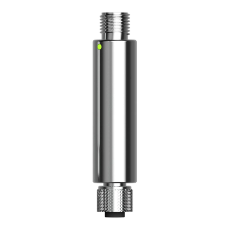
JUMO ecoTRANS pH 03 User manual

JUMO ecoTRANS pH 03
Microprocessor/transmitter / switching device
for pH value / redox voltage and temperature
Operating manual
20272300T90Z001K000
V2.00/EN/00506536


Content
1 Typographical conventions . . . . . . . . . . . . . . . . . . . . . . . . 6
1.1 Warning signs . . . . . . . . . . . . . . . . . . . . . . . . . . . . . . . . . . . . . . . . . . 6
1.2 Note signs . . . . . . . . . . . . . . . . . . . . . . . . . . . . . . . . . . . . . . . . . . . . . 6
2 Notes . . . . . . . . . . . . . . . . . . . . . . . . . . . . . . . . . . . . . . . . . . 7
3 Identifying the instrument version . . . . . . . . . . . . . . . . . . 8
3.1 Type description . . . . . . . . . . . . . . . . . . . . . . . . . . . . . . . . . . . . . . . . . 8
4 Mounting . . . . . . . . . . . . . . . . . . . . . . . . . . . . . . . . . . . . . . . 9
5 Electrical connection . . . . . . . . . . . . . . . . . . . . . . . . . . . . . 9
5.1 Connecting the sensor . . . . . . . . . . . . . . . . . . . . . . . . . . . . . . . . . . . 10
5.2 Customizing the special coaxial line . . . . . . . . . . . . . . . . . . . . . . . . 11
6 Commissioning . . . . . . . . . . . . . . . . . . . . . . . . . . . . . . . . 15
6.1 Brief description of the instrument . . . . . . . . . . . . . . . . . . . . . . . . . 15
6.2 Block diagram . . . . . . . . . . . . . . . . . . . . . . . . . . . . . . . . . . . . . . . . . 16
6.3 Applying the supply voltage . . . . . . . . . . . . . . . . . . . . . . . . . . . . . . 16
7 Adjusting / changing instrument functions . . . . . . . . . . 17
7.1 Process value display . . . . . . . . . . . . . . . . . . . . . . . . . . . . . . . . . . . 17
7.2 Operation . . . . . . . . . . . . . . . . . . . . . . . . . . . . . . . . . . . . . . . . . . . . . 18
7.3 Key function . . . . . . . . . . . . . . . . . . . . . . . . . . . . . . . . . . . . . . . . . . . 18
7.4 Selecting levels . . . . . . . . . . . . . . . . . . . . . . . . . . . . . . . . . . . . . . . . 20
7.5 User level (USER) . . . . . . . . . . . . . . . . . . . . . . . . . . . . . . . . . . . . . . . 21
7.6 Administrator level (ADMIN) . . . . . . . . . . . . . . . . . . . . . . . . . . . . . . . 22
7.7 Enable level (RIGHT) . . . . . . . . . . . . . . . . . . . . . . . . . . . . . . . . . . . . 23
7.8 Calibration level (CALIB) . . . . . . . . . . . . . . . . . . . . . . . . . . . . . . . . . 24
8 Configurable parameters . . . . . . . . . . . . . . . . . . . . . . . . 25
8.1 Inputs . . . . . . . . . . . . . . . . . . . . . . . . . . . . . . . . . . . . . . . . . . . . . . . . 26
8.1.1 Measurement input - main value (submenu "PH") . . . . . . . . . . . . . . 26
8.1.2 Measurement input - temperature (submenu "TEMP") . . . . . . . . . . 28
8.1.3 Binary input . . . . . . . . . . . . . . . . . . . . . . . . . . . . . . . . . . . . . . . . . . . . 29
8.2 Relays . . . . . . . . . . . . . . . . . . . . . . . . . . . . . . . . . . . . . . . . . . . . . . . 30
8.2.1 Binary output 1 (submenu "BIN.1") . . . . . . . . . . . . . . . . . . . . . . . . . 30
8.3 Analog outputs . . . . . . . . . . . . . . . . . . . . . . . . . . . . . . . . . . . . . . . . . 33
8.3.1 Main value (submenu "PH.OUT") . . . . . . . . . . . . . . . . . . . . . . . . . . . 33
8.3.2 Temperature (submenu "TE.OUT") . . . . . . . . . . . . . . . . . . . . . . . . . . 36
8.3.3 Calibration settings . . . . . . . . . . . . . . . . . . . . . . . . . . . . . . . . . . . . . . 39

Content
9 Calibration . . . . . . . . . . . . . . . . . . . . . . . . . . . . . . . . . . . . 40
9.1 General information . . . . . . . . . . . . . . . . . . . . . . . . . . . . . . . . . . . . . 40
9.1.1 When is calibration required? . . . . . . . . . . . . . . . . . . . . . . . . . . . . . . 40
9.2 Activating and starting calibration mode . . . . . . . . . . . . . . . . . . . . . 40
9.2.1 Starting calibration from the calibration level "CALIB" . . . . . . . . . . . 41
9.2.2 Starting calibration with the hot key (rapid access) . . . . . . . . . . . . . 41
9.3 Canceling calibration and error messages . . . . . . . . . . . . . . . . . . . 42
9.3.1 Zero point error . . . . . . . . . . . . . . . . . . . . . . . . . . . . . . . . . . . . . . . . . 42
9.3.2 Slope error . . . . . . . . . . . . . . . . . . . . . . . . . . . . . . . . . . . . . . . . . . . . 42
9.3.3 General error during calibration . . . . . . . . . . . . . . . . . . . . . . . . . . . . 42
9.3.4 Acknowledging errors . . . . . . . . . . . . . . . . . . . . . . . . . . . . . . . . . . . . 43
9.3.5 Additional measures . . . . . . . . . . . . . . . . . . . . . . . . . . . . . . . . . . . . . 43
9.4 One-point or two-point calibration . . . . . . . . . . . . . . . . . . . . . . . . . 43
9.4.1 Selecting one-point calibration . . . . . . . . . . . . . . . . . . . . . . . . . . . . . 43
9.4.2 Selecting two-point calibration . . . . . . . . . . . . . . . . . . . . . . . . . . . . . 44
9.5 Calibrating a pH measurement chain . . . . . . . . . . . . . . . . . . . . . . . 44
9.5.1 One-point calibration (zero point) . . . . . . . . . . . . . . . . . . . . . . . . . . . 44
9.5.2 Two-point calibration (zero point and slope) . . . . . . . . . . . . . . . . . . . 45
9.6 pH antimony measurement chain . . . . . . . . . . . . . . . . . . . . . . . . . . 48
9.7 Redox measurement chain . . . . . . . . . . . . . . . . . . . . . . . . . . . . . . . 48
9.7.1 General information . . . . . . . . . . . . . . . . . . . . . . . . . . . . . . . . . . . . . 48
9.7.2 One-point calibration (recommended calibration) . . . . . . . . . . . . . . 48
9.7.3 Two-point calibration . . . . . . . . . . . . . . . . . . . . . . . . . . . . . . . . . . . . 50
10 Analog output . . . . . . . . . . . . . . . . . . . . . . . . . . . . . . . . . . 52
10.1 Behavior of the output signal during calibration . . . . . . . . . . . . . . . 52
10.2 Behavior of the output signal in case of error . . . . . . . . . . . . . . . . . 52
10.3 Output signal in case of error . . . . . . . . . . . . . . . . . . . . . . . . . . . . . 53
10.4 Output signal when leaving the scaling range . . . . . . . . . . . . . . . . . 53
10.5 Manual mode of the analog output . . . . . . . . . . . . . . . . . . . . . . . . . 53
11 Relay output . . . . . . . . . . . . . . . . . . . . . . . . . . . . . . . . . . . 54
11.1 Relay behavior . . . . . . . . . . . . . . . . . . . . . . . . . . . . . . . . . . . . . . . . . 54
11.2 Binary output 1 (submenu "BIN.1") . . . . . . . . . . . . . . . . . . . . . . . . . 54
11.3 Manual mode of the relay output . . . . . . . . . . . . . . . . . . . . . . . . . . . 57
11.4 Behavior of the relay during calibration . . . . . . . . . . . . . . . . . . . . . . 58
11.5 Pulse function of the relay output . . . . . . . . . . . . . . . . . . . . . . . . . . 58
11.6 Behavior of the relay in case of error . . . . . . . . . . . . . . . . . . . . . . . . 60
11.7 Error detection . . . . . . . . . . . . . . . . . . . . . . . . . . . . . . . . . . . . . . . . . 60
Content
12 Display and LED messages . . . . . . . . . . . . . . . . . . . . . . . 62
12.1 Operating states of JUMO ecoTrans pH 03 . . . . . . . . . . . . . . . . . . . 62
12.2 Underrange . . . . . . . . . . . . . . . . . . . . . . . . . . . . . . . . . . . . . . . . . . . 62
12.3 Overrange . . . . . . . . . . . . . . . . . . . . . . . . . . . . . . . . . . . . . . . . . . . . 62
12.4 Broken sensor . . . . . . . . . . . . . . . . . . . . . . . . . . . . . . . . . . . . . . . . . 62
12.5 Short-circuit . . . . . . . . . . . . . . . . . . . . . . . . . . . . . . . . . . . . . . . . . . . 63
12.6 Initialization of dependent parameters . . . . . . . . . . . . . . . . . . . . . . 63
12.7 Calibration timer elapsed . . . . . . . . . . . . . . . . . . . . . . . . . . . . . . . . . 63
13 Operation via setup interface . . . . . . . . . . . . . . . . . . . . . 64
13.1 Operation with PC setup program . . . . . . . . . . . . . . . . . . . . . . . . . . 65
14 Technical data . . . . . . . . . . . . . . . . . . . . . . . . . . . . . . . . . 66
15 Environment/disposal . . . . . . . . . . . . . . . . . . . . . . . . . . . 69

6
1 Typographical conventions
1.1 Warning signs
1.2 Note signs
Danger
This symbol is used when there may be danger to personnel if the
instructions are ignored or not followed correctly!
Caution
This symbol is used when there may be damage to equipment or data if the
instructions are ignored or not followed correctly!
Caution
This symbol is used where special care is required when handling components
liable to damage through electrostatic discharge.
Note
This symbol is used to draw your special attention to a remark.
abc1Footnote
Footnotes are remarks that refer to specific points in the text. Footnotes
consist of two parts:
Marking in the text and the footnote text.
The markers in the text are arranged as continuous superscript numbers.
✱Action instruction
This symbol indicates that an action to be performed is described.
The individual steps are marked by this asterisk.
Example:
✱Loosen Phillips-head screws.

7
2 Notes
To protect the device from static electrical
discharge, the user must be electrostatically
discharged before touching the instrument!
All necessary settings are described in these
operating instructions. If any difficulties should
nevertheless arise during startup, please do not
tamper with the instrument in any way. By doing so,
you could endanger your rights under the instrument
warranty! Please contact the nearest subsidiary or the
head office in such a case.
Please read these operating instructions before
placing the instrument in service. Keep the manual in
a place which is accessible to all users at all times.
Please assist us in improving these operating
instructions where necessary.
For technical questions
Service hotline:
Phone: 0661 6003-300 or
0661 6003-653
Fax: 0661 6003-881300 or
0661 6003-881653
E-mail: [email protected]

8
3 Identifying the instrument version
The nameplate with the order code glued onto the side of the
instrument. The connected supply voltage must match the voltage
specified on the nameplate.
3.1 Type description
(1) Basic type
202723 JUMO ecoTRANS pH 03,
Microprocessor/transmitter / switching device for
pH value / redox voltage and temperature
(2) Output I (pH value / redox voltage)
888 Analog actual value output, freely programmable
(3) Output II (temperature)
000 None
888 Analog actual value output, freely programmable
(4) Output III (switching)
000 None
101 1 x relay, switching contact
(5) Extra codes
000 None
024 With PC setup software
(1) (2) (3) (4) (5)
Order code /--/
Order example 202723 / 888 - 888 - 101 / 000

9
4 Mounting
5 Electrical connection
The choice of cable, the installation, and the electrical connection
must conform to the requirements of VDE 0100 “Regulations on the
Installation of High-Voltage Systems with Nominal Voltages below
1000 V” or the appropriate local regulations.
❏To protect the device from static electrical discharge, the user
must be electrostatically discharged before touching the
instrument!
❏The electrical connection must only be carried out by qualified
personnel.
❏Electromagnetic compatibility conforms to the standards and
regulations cited in the technical data.
❏Operates only on SELV or PELV circuits.
❏The instrument is not suitable for installation in areas with an
explosion hazard.
Apart from faulty installation, incorrect settings on the instrument
may also affect the proper functioning of the subsequent process or
lead to damage. Safety devices should always be provided that are
independent of the instrument (such as overpressure valves or
≤ 75
-10
+60
°C

10
temperature monitors/limiters) and only capable of adjustment by
specialist personnel. Please observe the relevant safety regulations
for such matters.
❏The load circuit must be fused for the maximum relay current, in
order to prevent the output relay contacts from becoming
welded in the event of a short circuit.
❏The supply voltage must be fed into the instrument through a
125-mA fuse, medium time lag or comparable protection by
means of a separate branch.
❏Do not connect any additional loads to the screw terminals for
the supply of the instrument.
❏Any electrical connection deviating from the connection diagram
may cause the instrument to be destroyed.
❏Lay the input, output, and supply lines so they are physically
separated from each other and are not parallel.
❏Lay probe cables only as continuous lines, twisted and shielded
(not via series terminals or similar arrangements).
❏Fluctuations in supply voltages are only permitted within
specified tolerances (see datasheet 20.2723).
❏The instrument must not be mounted or dismounted unless it is
in dead state and/or the lines are not connected.
5.1 Connecting the sensor
To connect the pH redox electrode, special coaxial lines are
recommended as specified by JUMO datasheet 202990. Standard
commercial antenna or computer lines with coaxial construction are
generally not suitable. They may result in faulty readings or could
destroy the pH or redox electrode.
The semiconducting layer (see Fig. (2)) of the special coaxial line must
be at a sufficient distance to prevent a short circuit with the inner
conductor on the transmitter terminal. The coaxial line may be sensitive
to touch or motion due to the high internal resistance of a pH electrode.
This must be taken into consideration when laying the cable.

11
5.2 Customizing the special coaxial line
Example:
✱Strip insulation from the line as shown in the drawing. Remove
the black semiconducting layer (2) from the insulation of the inner
conductor as indicated.
✱Twist the shield (1) and insulate with a shrink tubing.
✱Insulate the black semiconducting layer with shrink tubing (2) to
prevent short circuits.
✱Place ferrules on the line ends.
~40 mm
(1)
(2)
(1)
(2)

12
Terminal assignment
P
K1
EXIT
4321
5876
13 L-L+ 16
9121110

13
Measurement
inputs Terminal assignment Symbol
pH electrode
or
Redox
combination
electrode
16
13
Reference system
(braiding)
Glass electrode/metal
electrode (inner conductor)
pH glass electrode
or
Metal electrode
(with isolated
reference
electrode)
13 Glass electrode/metal
electrode (inner conductor)
Reference
electrode
(with isolated
electrodes)
16 Reference system
Liquid potential
(connect only with
symmetrical
connection)
12
Resistance
thermometer
in 2-wire circuit
9
10
16 13
13
16
12
ϑ
910

14
Binary input 11
12
Outputs Terminal assignment Symbol
I
Analog process
value output pH/
redox
(galvanically
isolated)
5
6
+
-
II
Analog process
value output -
temperature
(galvanically
isolated)
7
8
+
-
III
Relay
1
3
4
Pin
Break (SPST-NC)
Make (SPST-NO)
Power
supply Terminal assignment Symbol
Power
supply
(with reverse
polarity protection)
DC 20 to 30 V
L-
L+
12
11
56
+-
78
+-
413
PS
Ö
L- L+
-+

15
6 Commissioning
6.1 Brief description of the instrument
The instrument measures and, depending on the configuration,
regulates the pH or redox voltage in aqueous solutions. The range
of applications includes general water and wastewater
management, measuring drinking and wastewater, process water,
surface and ocean water, swimming pool and fountain water, and
professional aquariums, etc.
The transmitter has two analog inputs. The first analog input (main
input for pH value or redox voltage) is provided for connecting
electrodes with an isolated reference electrode. The instrument is
also prepared for connecting antimony electrodes. A resistance
thermometer (Pt 100 or Pt 1000) can be connected to the second
analog input.
Up to two analog outputs and one relay switching contact are
available. The analog outputs are galvanically isolated and assigned
to the inputs. Either the main value (pH or redox voltage) or the
temperature can be assigned to the relay contact.
The keys and integrated LD display are used to operate and
configure the instrument. This can also be done very conveniently
with the setup connection (Notebook / PC) using the optional setup
program. The setup program can also be used to print configuration
data. This makes system documentation easier.
Instruments are delivered with a calibration verification tool that is
used to document instrument and calibration data.
With the correct wiring of device and sensor, and
correct configuration of the device, a measure-
ment without calibration should be possible.
If this is not the case, influencing factors such as
short circuit, open circuit, EMC and flow conditi-
ons should also be considered.

16
6.2 Block diagram
6.3 Applying the supply voltage
If the instrument has been correctly connected, all LCD segments are
briefly lit immediately after the supply voltage is applied.
Note:
After the instrument is started, the output signal is 0 V or 0 mA. The
relay is in idle state (inactive). After about 2 seconds, the JUMO
ecoTRANS pH 03 begins working according to the configuration.
Signal preparation
Supply voltage
DC 20...30 V
Temperature sensor
Resistance thermometer
- Pt100
- Pt1000
Output - pH/
Redox voltage
- 0(4)...20 mA
- 0(2)...10 V
- 20...0(4) mA
- 10...0(2) V
Output - temperature
Temperature signal
- 0(4)...20 mA
- 0(2)...10 V
- 20...0(4) mA
- 10...0(2) V
Output - switching
1x relay (changeover contact)
Function:
limit value,
pulse function,
calibration timer
Keyboard LC display
PC/notebook
setup program
Binary input
For potential-free contact
Function:
- Freezing the switching contact
- Freezing the inputs,
Outputs and display
pH or redox sensor
Electrode or
electrode with isolated
reference electrode

17
7 Adjusting / changing instrument functions
Changes can be made in the setup program or with the JUMO
ecoTRANS pH 03 keys.
7.1 Process value display
The process value display can be either
- in static mode or in
- alternating mode
Static display (default setting)
Compensated pH value redox voltage
Alternating display (at a fixed rate of about 3 seconds)
Compensated pH value Current temperature
with current unit
Change from static display to alternating display
✱Press the key (for less than 2 sec)
Change from alternating display to static display
✱Press the key (for less than 2 sec)
About 3
P
P

18
7.2 Operation
The instrument can be operated on different levels.
Access to all levels (except the user level) is protected by different
codes2.
On the User level (USER) all parameters can be viewed and/or
modified depending on user rights1(see Enable level).
On the Calibration level (CALIB) the electrode zero point (intercept
point) and/or the electrode slope can be calibrated.
On the Enable level (RIGHT) user rights can be defined.
On the Administrator level (ADMIN) all parameters can be set
(configured).
The different codes and settings on the Enable level make it
possible to assign different user rights to users.
1The factory setting for all parameters is "READ," i.e. all
parameters can only be read on the User level, not changed.
2Codes for the Administrator and Enable levels can only be
changed with the setup program
(see Section 13 "Operation via setup interface", page 64).
7.3 Key function
- The UP and DOWN keys are used to select a submenu in the
main menu and to scroll forward and backward.
- The P key switches to the corresponding submenu.
- To change (edit) a parameter, press the P key.
- When the parameter is released for editing, the value flashes. If
the parameter is locked, "LOCK" appears in the display.
- To change the parameter, it must be unlocked on the Enable level
(changed from "rEAd" to "Edit").
After 60 seconds with no user activity (no keystrokes),
the display reverts to process value display.
This timeout function is not active during calibration!

19
- To increase or reduce the value, press the UP or DOWN key.
- The value can then be accepted with the P key.
- The EXIT key is used to cancel the entry and switch to the next
higher level.

20
7.4 Selecting levels
1Timeout (automatically jumps back after 60 sec. with no activity).
2See Section 7.5 "User level (USER)", page 21.
3See Section 7.6 "Administrator level (ADMIN)", page 22.
4See Section 7.7 "Enable level (RIGHT)", page 23.
5See Section 7.8 "Calibration level (CALIB)", page 24.
Process value display
(Operator level)
2
(Enable level)
4
CALIB
(Calibration level)
5
(Administrator level)
3
Selection level
> 2 seconds
EXIT
1
P
P
EXIT
P
EXIT
P
EXIT
P
EXIT
USER
RIGHT
ADMIN
Table of contents
Other JUMO Transmitter manuals

JUMO
JUMO CTI-500 User manual

JUMO
JUMO 907021/10 User manual

JUMO
JUMO dTRANS p02 DELTA User manual

JUMO
JUMO SIRAS P21 AR User manual

JUMO
JUMO CTI-500 Use and care manual

JUMO
JUMO CTI-750 User manual

JUMO
JUMO dTRANS T03 J User manual

JUMO
JUMO AQUIS 500 pH User manual

JUMO
JUMO CTI-750 User manual

JUMO
JUMO ecoTRANS Lf 01 User manual

JUMO
JUMO B 90.7027.1 User manual

JUMO
JUMO dTRANS T03 Series User manual

JUMO
JUMO CTI-750 User manual

JUMO
JUMO dTRANS AS 02 User manual

JUMO
JUMO TRANS T06 Junior User manual

JUMO
JUMO dTRANS T07 Reference guide

JUMO
JUMO dTRANS T02 PCP User manual

JUMO
JUMO JUMO dTRANS p20 DELTA User manual

JUMO
JUMO dTRANS T02 LCD User manual

JUMO
JUMO AQUIS 500 CR User manual