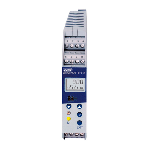
JUMO ecoTRANS Lf 01 User manual

ecoTRANS Lf 01/02
Transmitter /
Switching Device
for Conductivity
Type 202731
B 20.2731.0
Operating Instructions
02.07/00435548


1 Notes ______________________________________________ 4
2 Identifying the device version ________________________ 5
2.1 Type designation ____________________________________________ 5
3 Mounting ___________________________________________ 6
4 Electrical connection ________________________________ 6
5 Electrical connection ________________________________ 8
6 Commissioning ____________________________________ 11
6.1 Fundamentals of conductivity measurement ___________________ 11
6.2 Applying the supply voltage __________________________________ 11
6.3 Altering the device functions _________________________________ 12
6.3.1 Operation through the Setup __________________________________ 13
6.3.2 Operation through the teach-in connector
(only on the JUMO ecoTRANS Lf 02) ___________________________ 15
6.4 Calibration _________________________________________________ 17
6.4.1 Characteristics of sensor and medium _______________________ 18
6.4.2 Preparing to calibrate the cell constant or temperature coefficient _ 19
6.4.3 Calibrating the cell constant ________________________________ 20
6.4.4 Calibrating the temperature coefficient _________________________ 20
6.5 Manual entry of temperature coefficient and cell constant ________ 21
6.6 Manual mode ______________________________________________ 22
6.7 Analog output (JUMO ecoTRANS Lf 01) _______________________ 23
6.8 Relay output (JUMO ecoTRANS Lf 02) ________________________ 25
6.9 LED messages _____________________________________________ 27
7 Technical data _____________________________________ 28
7.1 General characteristics ______________________________________ 30
8 Environment / waste disposal _______________________ 31

4
1 Notes
To protect the instrument from electrostatic discharge,
users must discharge themselves electrostatically before
touching the instrument !
All necessary settings are described in these
Operating Instructions. However, if any difficulties
should still arise during start-up, please do not carry
out any manipulations on the unit. You could
endanger your rights under the instrument warranty!
Please contact the nearest subsidiary or the head
office in such a case.
Please read these operating instructions before
starting up the instrument. Keep the manual in a place
which is accessible to all users at all times. Please
assist us to improve these operating instructions,
where necessary.
Phone + 49 661 6003-0
Fax + 49 661 6003-607
E-mail: [email protected]

5
2 Identifying the device version
The nameplate with the order code is glued to the side of the
housing. The supply voltage must correspond to the voltage given
on the nameplate.
2.1 Type designation
(1) Basic type
202731 JUMO ecoTRANS Lf 01/02,
Microprocessor transmitter / switching device for
conductivity
(2) Output
01 with analog output
02 with relay output
(3) Measuring range (freely programmable)
011 0 — 5 µS/cm / K = 0.01 1/cm
012 0 — 20 µS/cm / K = 0.01 1/cm
013 0 — 200 µS/cm / K = 0.1 1/cm
014 0 — 1000 µS/cm / K = 0.1 1/cm
015 0 — 2 mS/cm / K = 1.0 1/cm
016 0 — 20 mS/cm / K = 1.0 1/cm
017 0 — 100 mS/cm / K = 10.0 1/cm
018 0 — 200 mS/cm / K = 10.0 1/cm
(4) Extra codes
000 none
024 including PC setup software
(1) (2) (3) (4)
Order code 202731 / - /
Order example 202731 / 01 - 015 / 000

6
3 Mounting
4 Electrical connection
The choice of cable, the installation, the fusing and the electrical
connection must conform to the requirements of VDE 0100
“Regulations on the Installation of Power Circuits with Nominal
Voltages below 1000 V” or the appropriate local regulations.
❏To protect the instrument from electrostatic discharge, users
must discharge themselves electrostatically before touching the
instrument!
❏The electrical connection must only be carried out by qualified
personnel.
❏Electromagnetic compatibility conforms to the standards and
regulations cited in the technical data.
❏The instrument is not suitable for use in areas with an explosion
hazard (Ex areas).
Apart from faulty installation, incorrect settings on the instrument
may also affect the proper functioning of the subsequent process or
90
(1) (2)
-10
+60
°C
93
93.5
45 22.5
51.5
34.5
22.5

7
lead to damage. Safety devices should always be provided that are
independent of the instrument (such as overpressure valves or
temperature monitors/limiters) and only capable of adjustment by
specialist personnel. Please observe the relevant safety regulations
for such matters.
❏The load circuit must be fused for the maximum relay current, in
order to prevent the output relay contacts becoming welded in
the event of a short circuit.
❏Do not connect any additional loads to the screw terminals for
the supply of the instrument.
❏Any electrical connection other than that specified in the
connection diagram may result in the destruction of the
instrument.
❏Run input, output and supply cables separately and not parallel
to one another.
❏Sensor leads must only be implemented as twisted and
shielded, uninterrupted cables (not routed via terminal blocks
etc).
❏Supply fluctuations are only permissible within the specified
tolerances (see Data Sheet 20.2731, page 3/6).

8
5 Electrical connection
4
5
7
4
6
6
8
L+
L-
1
2
3
1
2
3
1
23
4
4
6
7
8
Setup connection or connection for
the teach-in connector
(on the JUMO ecoTRANS Lf 02)
LED for the indication of operating states
Head of a
JUMO
conductivity
cell with
Hirschmann
connector
Head of a
JUMO
conductivity
cell with
M12
connector

9
Connection of conductivity cell
Conductivity cell (JUMO types) JUMO
ecoTRANS
Lf 01/02
Angled connector
to DIN 43 650
(Hirschmann
connector)
Fixed cable M12 plug
Outer electrode white 1 8
Inner electrode 2 brown 2 7
Temperature
compensation
1
3
yellow
green
3
4
4
6

10
Outputs Terminal assignments Symbol
Analog
measurement
output
(electrically
isolated)
only with JUMO
ecoTRANS Lf 01
1
3
+
-
Relay
only with JUMO
ecoTRANS Lf 02
1
2
3
n.c. (break)
common
n.o. (make)
Measurement
inputs Terminal assignments Symbol
Conductivity
cell
8
7
outer electrode,
on coaxial cells
inner electrode,
on coaxial cells
Resistance
thermometer
in 3-wire circuit
4
5
6
Resistance
thermometer
in 2-wire circuit
4
6
Supply
voltage Terminal assignments Symbol
Supply
voltage
L-
L +
13
+-
321
PS
Ö
78
ϑ
45 6
ϑ
46
L- L+
-+

11
6 Commissioning
6.1 Fundamentals of conductivity measurement
Principle of measurement
Electrolytic conductivity measuring cells basically consist of two
metal plates arranged opposite each other which are immersed in
the solution to be measured. The conductivity of the solution is
determined through the measuring voltage and the resulting
measuring current.
The current between the metal plates depends on their geometry
(distance and area). The cell constant describes this dependence.
Subject to manufacturing tolerances, or because of dirt or wear, the
actual cell constant of a measuring cell may deviate slightly from its
nominal value. This deviation is reflected by the relative cell
constant that is adjustable on the conductivity transmitter.
The conductivity of a solution depends on temperature. The
temperature coefficient of the solution describes the dependence
of conductivity and temperature. Since conductivity is not always
measured at the reference temperature, the temperature coefficient
can be adjusted on the conductivity transmitter.
6.2 Applying the supply voltage
If the device has been connected correctly, the LED1will light up.
- green, constant status display
- red, constant the relay is active
(only on the JUMO ecoTRANS Lf 02)
- red, flashing alarm
- measuring range infringed (overrange)
- temperature range infringed (over/underrange)
- temperature probe not connected correctly
1also see Chapter 6.9 “LED messages”, page 27.

12
6.3 Altering the device functions
Alterations can only be carried out in the setup program.
Exception: the switching point of the JUMO ecoTRANS Lf 02 can
also be determined by the device, through the teach-in connector.
Operation via the setup interface
Caution
The setup interface and the measurement inputs for conductivity
and temperature are not electrically isolated. This means that, in
unfavorable conditions, equalizing currents may flow when the PC
interface is connected. These equalizing currents may result in
damage to the devices connected.
However, there is no danger if the measurement circuit of the
transmitter is electrically isolated from ground. If this is not assured,
then one of the following safety measures should be taken:
1) Use a computer without electrical coupling to ground
(e.g. battery-operated notebook).
The computer must not be connected to a network.
2) Disconnect the measurement inputs of the transmitter before
connecting the PC interface.
JUMO ecoTRANS Lf 01/02
PC interface cable
JUMO PC setup software
multilingual D / GB / F
PC or notebook with RS232 interface
Operating system:
–Windows’98
®
– Windows 2000®
–WindowsXP
®
–WindowsNT
®4.0 or higher

13
6.3.1 Operation through the Setup
Analog input: Conductivity
In this window, you will be able to make settings with respect to the
conductivity input.
(1) Navigation tree
The navigation tree allows quick access (double-click) to the
individual setting options.
(2) Diagnosis window
A soon as a connection with a device has been established,
the latest data are shown here.
(3) Working area
If you click on the arrow ( ), the setting options will be shown.
A double-click on the text will call up the corresponding editing
window.
(1)
(2)
(3)

14
Lead compensation:
The effect of long cables can be compensated on ranges above
about 20 mS/cm by entering the lead resistance. This is done by
entering the sum of the resistances for the incoming/return cables.
Analog input: Temperature
In this window, you can make settings with respect to the
temperature input, such as probe type, connection circuit (e.g.
2-wire), reference temperature and so on.
Analog output (JUMO ecoTRANS Lf 01 only)
In this window, you can make settings concerning the analog
output for conductivity, such as current/voltage output, scaling and
so on.
Relay output (JUMO ecoTRANS Lf 02 only)
In this window, you can make settings concerning the relay output,
such as min/max contact, switching point and so on.
Calibration timer
In this window, you will be able to specify calibration intervals, after
which a calibration has to take place.
When the calibration timer has run down, the LED alternately
switches between green and red.
Customized linearization for the temperature probe
This is used to adapt any temperature probe to the temperature
input of the JUMO ecoTRANS Lf 01/02.
In the “Analog input for temperature” window, select “Customized
probe type”.
Note
Because of the data format used, only the first and last interpolation
points read back will correspond to the interpolation points
transmitted. The intermediate values are calculated inside the
device as equally spaced values.

15
Characteristics of sensor and medium
Parameters such as the relative cell constant and temperature
coefficient can be found here.
These data will only be displayed if they have been read out from
the device or the appropriate saved file has been opened.
6.3.2 Operation through the teach-in connector
(only on the JUMO ecoTRANS Lf 02)
In the learning (teach-in) mode, the switching point of the relay can
be set using the teach-in connector (without the setup program).
Note
In the learning mode, the relay behaves as set in the setup program
under “Response in calibration operation”.
The conductivity measured in the learning mode corresponds to the
desired switching point.
The switching function has been defined so that the relay switches
when the switching point (setpoint) has been exceeded. The
hysteresis is set at 2% of the measuring range. A range with the
correct cell constant must have been configured.
Procedure
- The JUMO ecoTRANS Lf 02 is operating (a conductivity
cell has been attached, the supply voltage has been connected).
✱Immerse the conductivity cell into a solution with a known
(desired) conductivity.
✱Plug the teach-in connector into the socket on the
JUMO ecoTRANS Lf02.
The LED flashes green rapidly (4 times per second),
green = the learning mode is active.
- The teach-in procedure lasts about 10 seconds.
Afterwards, the LED should flash green slowly (once per second)
= OK, the learning mode has been successfully completed.
If the LED flashes red slowly (once per second)
= ERROR, the learning mode has not been successfully completed.

16
If the switching point has been found:
✱Pull out the teach-in plug.
The device operates with the switching point that has been
learned.
If the switching point has not been found:
✱Pull out the teach-in plug.
The device operates with the original switching point.
Note
The learning mode can be activated by plugging the teach-in
connector in again.
The learning mode can also be started without a connected
conductivity cell, whereby an ohmic resistance simulates the
resistance of the liquid measured by the conductivity cell.
The required resistance can be determined as follows:
R = ohmic resistance [Ω]
K = cell constant of the actual conductivity cell [1/cm]
Lf = conductivity at the desired switching point [S/cm]
RK
Lf
----=

17
Example
JUMO ecoTRANS Lf 02 with the range
0 — 2 mS/cm; cell constant K = 1.0 1/cm
desired switching point w = 0.8 mS/cm = (0.0008 S/cm)
The resistance that must be connected in place of the conductivity
cell has a value of 1250 Ω.
6.4 Calibration
General
The cell constants of conductivity cells may vary somewhat
depending on the type used, and additionally change during
operation, for example, due to deposits such as lime, or as a result
of wear. This results in a change in the output signal from the cell. It
is therefore necessary for the user to be able to compensate for the
deviations of the cell constant from the nominal value, either by
manual entry or an automatic calibration of the cell constant Krel.
The conductivity of a solution varies with temperature, so for correct
measurement both the temperature and the temperature coefficient
of the solution being measured must be known. The temperature
can either be measured automatically, with a Pt100 or Pt1000
temperature probe or a customized temperature probe, or set
manually by the user. The temperature coefficient can be
determined automatically by the conductivity transmitter, or entered
manually.
The time intervals between calibrations depend on the conditions in
which the cell is used.
The device can draw your attention to a scheduled calibration by
means of the calibration timer.
R= 1.0 1/cm = 1250 Ω
0.0008 S/cm

18
6.4.1 Characteristics of sensor and medium
The “Characteristics of sensor and medium” window is called up
with the “screwdriver” icon.
The data can be manually entered here or determined empirically
and transferred to the device using an integrated routine.

19
6.4.2 Preparing to calibrate the cell constant or temperature
coefficient
✱Connect the conductivity cell to the JUMO ecoTRANS Lf 01/02.
✱Connect the JUMO ecoTRANS Lf 01/02 to the PC or laptop by
means of the PC interface cable (Part No. TN 95/00350260).
Caution
The PC or notebook must not be electrically connected to ground
or connected to a network, see page 12.
✱Apply supply voltage.
✱Start the setup program.

20
6.4.3 Calibrating the cell constant
The sequence is defined by the setup program.
✱Immerse the conductivity cell into a solution with a known
conductivity.
✱In the setup program, start “Calibration of the cell constant” by
activating the “Relative cell constant” button.
✱Accept the calculated cell constant with “Yes” or discard it with
“No”.
Note
If the calibration of the cell constant has been concluded with “Yes”,
the calibration timer is reset and restarted.
6.4.4 Calibrating the temperature coefficient
Calibration of the temperature coefficient takes place at two
temperatures (temperature 1 = reference temperature and
temperature 2 = working temperature).
The uncompensated conductivities that were determined at these
temperatures are used to specify the linear temperature coefficient.
The sequence is defined by the setup program.
✱Immerse the conductivity cell and the temperature probe (if
available) into the solution.
✱In the setup program, start “Calibration of the temperature
coefficient” by activating the “Temperature coefficient” button
(start at the reference temperature or start at the operating
temperature).
This manual suits for next models
1
Table of contents
Other JUMO Transmitter manuals

JUMO
JUMO CTI-750 User manual

JUMO
JUMO 907021/10 User manual

JUMO
JUMO JUMO dTRANS p20 DELTA User manual
JUMO
JUMO DELOS SI User manual

JUMO
JUMO 40.2005 User manual

JUMO
JUMO AQUIS 500 CR User manual

JUMO
JUMO dTRANS T02j User manual

JUMO
JUMO TAROS S47 P User manual

JUMO
JUMO dTRANS T04 User manual

JUMO
JUMO dTRANS T03 Series User manual

JUMO
JUMO dTRANS T08 01 User manual

JUMO
JUMO CTI-500 Use and care manual

JUMO
JUMO dTRANS T01 Junio User manual

JUMO
JUMO TRANS T06 Junior User manual

JUMO
JUMO CTI-500 User manual

JUMO
JUMO ecoTRANS pH 03 User manual

JUMO
JUMO dTRANS p02 User manual

JUMO
JUMO dTRANS O2 01 User manual

JUMO
JUMO dTRANS T05 User manual

JUMO
JUMO dTRANS p02 User manual