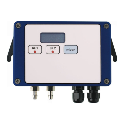
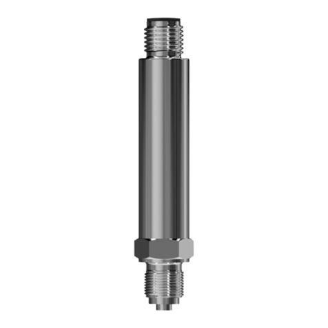
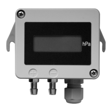
JUMO dTRANS p02 User manual

dTRANS p02
Pressure Transmitter
B 40.4385
Operating Instructions
07.01/00365643
All manuals and user guides at all-guides.com
all-guides.com

All manuals and user guides at all-guides.com

Contents
1 Typographical conventions __________________________ 4
1.1 Warnings ____________________________________________________ 4
1.2 Note signs ___________________________________________________ 4
2 General ____________________________________________ 5
2.1 Preface _____________________________________________________ 5
2.2 Application __________________________________________________ 6
3 Delivery package ___________________________________ 7
4 Instrument identification _____________________________ 8
4.1 Nameplate __________________________________________________ 8
4.2 Type designation _____________________________________________ 9
4.3 Dimensions/details __________________________________________ 10
4.4 Dimensions: "non-flush pressure connections" __________________ 10
4.5 Dimensions: "flush pressure connections" ______________________ 11
5 Instrument description _____________________________ 12
5.1 Technical data _____________________________________________ 12
6 Mounting __________________________________________ 14
6.1 General ____________________________________________________ 14
6.2 Prior to mounting ____________________________________________ 14
6.3 Mounting by the pressure connection __________________________ 15
6.4 Mounting by the housing _____________________________________ 15
6.5 Pressure connection _________________________________________ 16
6.6 Use inside the Ex area _______________________________________ 16
7 Installation ________________________________________ 17
7.1 Electrical connection _________________________________________ 17
7.2 Testing the output signal _____________________________________ 19
7.3 Connection of a HART®modem ______________________________ 19
7.4 Connection of a HART® communicator ________________________ 20
7.5 Testing the HART®communication ____________________________ 20
7.6 Electrical connection in the hazardous (Ex) area _________________ 21
All manuals and user guides at all-guides.com

Contents
8 Commissioning ____________________________________ 23
8.1 Characteristic _______________________________________________ 23
8.2 Self-test ____________________________________________________ 24
8.3 Measuring the absolute pressure ______________________________ 26
8.4 Measuring the gauge pressure ________________________________ 29
9 Adjustment options ________________________________ 32
9.1 The level concept ___________________________________________ 32
9.2 Sequence for keypad operation _______________________________ 33
9.3 Display level ________________________________________________ 34
9.4 Parameter level _____________________________________________ 35
9.5 Detailed explanations ________________________________________ 38
10 Opening the instrument ____________________________ 41
10.1 Unscrewing the bezel ring or housing cover ____________________ 41
11 Rotating the instrument ____________________________ 42
11.1 Rotating ____________________________________________________ 42
12 Maintenance _______________________________________ 43
12.1 Trouble-shooting ____________________________________________ 43
13 Appendix __________________________________________ 46
13.1 EC Type-Examination Certificate ______________________________ 46
13.2 Supplement to EC Type-Examination Certificate ________________ 52
13.3 EU Declaration of Conformity ATEX ____________________________ 56
13.4 Settings ____________________________________________________ 58
All manuals and user guides at all-guides.com

All manuals and user guides at all-guides.com

4
1 Typographical conventions
1.1 Warnings
1.2 Note signs
Danger
This sign is used when there may be danger to personnel if the instructions
are disregarded or not followed accurately!
Caution
This sign is used when there may be damage to equipment or data if the
instructions are disregarded or not followed accurately!
Note
This sign is used when your special attention is drawn to a remark.
➩Reference
This sign refers to further information in other chapters or sections.
abc1Footnote
Footnotes refer to certain points in the text. Footnotes consist of two parts:
Markings in the text and the footnote text.
The markings in the text are arranged as continuous superscript numbers.
✱Action
This sign indicates that an action to be performed is described.
The individual steps are marked by this asterisk.
Example:
✱Remove crosspoint screw.
✱Press the key.
All manuals and user guides at all-guides.com
all-guides.com

5
2 General
2.1 Preface
Please read these Operating Instructions before commissioning the instru-
ment. Keep the manual in a place which is accessible to all users at all times.
Please assist us to improve these operating instructions where necessary.
Your suggestions are welcome.
Phone Germany (0661) 6003-714
abroad (+49) 661 6003-0
Fax Germany (06 61) 6003-605
abroad (+49) 661 603-607
All necessary settings are described in this manual. If any difficul-
ties should still arise during commissioning, you are asked not to
carry out any unauthorized manipulations on the unit. You could
endanger your rights under the instrument warranty!
Please contact the nearest subsidiary or the main factory in such a
case.
When returning modules, assemblies or components, the regula-
tions of EN 100 015 “Protection of electrostatically sensitive com-
ponents” must be observed. Use only the appropriate ESD pack-
aging for transport.
Please note that we cannot accept any liability for damage caused
by ESD.
ESD=electrostatic discharge
All manuals and user guides at all-guides.com

2 General
6
2.2 Application
General The type JUMO dTRANS p02 is used to measure the pressure of corrosive
and non-corrosive gases, vapors and liquids. The pressure transmitter uses
the piezo-resistive effect to make the measurement. The output signal is a pro-
portional DC current which is linearly proportional to the input pressure.
Version with
Ex protection The JUMO dTRANS p02 pressure transmitter in intrinsically safe version
marked II 1/2 G EEx ia IIC T6, is suitable for mounting within the hazardous
area Zone 1 for connection to Zone 0.
The EC Type-Examination Certificate for the JUMO dTRANS p02 is:
PTB 98 ATEX 2194
If this pressure transmitter is used in areas with potentially explosive atmo-
spheres, the appropriate regulations for installing and operating equipment in
such areas must be observed.
The diaphragms of the JUMO dTRANS p02 pressure transmitter
must not be damaged. Do not insert any objects into the bores of
the pressure connections!
All manuals and user guides at all-guides.com

7
3 Delivery package
Operating
Instructions
B 40.4385
These operating instructions are a comprehensive guide for the installation,
electrical connection, commissioning, operation and parameterization of the
JUMO dTRANS p02 pressure transmitter.
JUMO
calibration
certificate
A JUMO calibration certificate and a setup print-out comes with each pressure
transmitter. These documents contain information on the parameter settings
and/or the measured characteristic data for the transmitter concerned.
If this calibration certificate is lost, or should you need an additional one, it can
be ordered from JUMO stating the serial No. of the pressure transmitter (see
nameplate),
➩see addresses of suppliers on the back of the operating instructions
Setup
program All the parameters of the transmitter can be conveniently checked and
adjusted by using the setup program. Furthermore, additional functions are
available such as:
- recording of measurements
- graphical display of temperature and pressure
- comprehensive diagnostic messages
- indication of the complete order code and instrument configuration
(for repeat orders).
The setup program is available on request, at extra cost,
Sales No. 40/00365072.
HART®modem The HART®modem serves to connect the JUMO dTRANS p02 to a PC. The
HART®modem is available on request, at extra cost,
Sales No. 40/00345666.
Power supply A supply unit with a supply isolator is available on request, at extra cost,
Sales No. 40/00389710.
All manuals and user guides at all-guides.com

8
4 Instrument identification
4.1 Nameplate
Nameplate on a pressure transmitter without approval for use within the
hazardous (Ex) area.
Nameplate on a pressure transmitter with approval for use within the hazard-
ous (Ex) area.
All manuals and user guides at all-guides.com

9
4 Instrument identification
4.2 Type designation
1not for nominal range -1 to 100 bar and -1 to 600 bar gauge pressure
2not with Protection EEX ia II C
(1) Basic type
404385 pressure transmitter dTRANS p02 with sensing element
in piezo-resistive or thin-film technology
(2) Basic type extensions
0none
1 Protection EEx ia IIC (PTB 98 ATEX 2194)
4 for increased temperature of medium up to 200°C1
(only with process connections 571, 604, 606, 613 and 616)2
9 special version
(3) Nominal input range
414 -100 to +100 mbar gauge pressure
453 -0.6 to +0.6mbar gauge pressure
457 -1 to +4 bar gauge pressure
461 -1to +25 bar gauge pressure
464 -1to +100 bar gauge pressure
468 -1to +600 bar gauge pressure
487 0 to +0.6 bar absolute pressure
491 0 to +4 bar absolute pressure
495 0 to +25 bar absolute pressure
(4) Output
405 4 — 20mA with HART®protocol
(5) Process connection
504 1/2" pipe to EN 837
512 1/2" - 14 NPT to DIN 837
564 1/2" - 14 NPT female
571 3/4" pipe flush to DIN 8371
604 taper connection with slotted ring nut DN25 to DIN 11 8511,2
606 taper connection with slotted ring nut DN401,2
613 clamp connection DN25 to DIN 32 6761,2
616 clamp connection DN50 to DIN 32 6761,2
(6) Material of process connection
20 stainless steel
82 Hastelloy C276, Mat. Ref. 2.4819
99 special material
(7) Electrical connection
06 screw terminals
33 Harting connector Han 7D /Han 8D (8U)
(8) Filling medium of measuring system
0none
1 silicone oil1
2 halogenized filling oil1
(1) (2) (3) (4) (5) (6) (7) (8)
Order code 404385 / 405
Order example 404385 / 0 - 457 - 405 - 504 - 20 - 06 - 1
All manuals and user guides at all-guides.com
all-guides.com

4 Instrument identification
10
4.3 Dimensions/details
4.4 Dimensions: "non-flush pressure connections"
NTS 527
170
76
L
G 1/2
15
G 1/2
69
131
Ø76
(4)
(5)
(6) (7)
(1)
(3)
(2)
(8)
(9)
(10)
(1) Cover for electrical connection (6) Electrical connection,
M 20x1.5 cable gland
(2) PE connection (7) Blanking plug (electrical connection or
instrument mounting possible)
(3) Cover flap (keypad underneath) (8) Electrical connection,
Harting connector Han 7D / Han 8D (8U)
(4) Bezel (9) LCD display
(5) Process connection (10) Special version “Process connection":
pressure sensor connected to indicating
unit via attached cable
512
1/2-14 NPT
18
504
20
33
Ø17.5 Ø6
564
SW 27
18
22.5
1/2-14 NPT-Innen 27 a/f
1/2-14 NPT female
All manuals and user guides at all-guides.com

11
4 Instrument identification
4.5 Dimensions: "flush pressure connections"
DN
25
40
D1D2D3
RD 52x1/6
RD 65x1/6
D4L1L2
21
NTS
604
606
Ø56
Ø44 Ø48 Ø78
Ø35 Ø63 15
D2
D1
D3
D4
L1
L2
2
604 / 606
Kegelstutzen mit Nutüberwurfmutter
nach DIN 11 851
D1
D2
15
3
613 / 616
nach DIN 32 676
50
D1D2
1"
1.5" 25 25 Ø50.5 Ø43.5
2" 40
51 51 Ø64 Ø56.5
NTS
613
616
DN
DIN32676 DN
(Zoll) Storlek
SMS 3017
Nominal Size
ISO 2852
25
SW 32
Ø31.9
G 3/4
32
16
20
571
604 / 606
taper connection with slotted ring nut
to DIN 11 851 613 / 616
to DIN 32 676
(inch)
3/4" pipe
32 a/f
All manuals and user guides at all-guides.com

12
5 Instrument description
5.1 Technical data
5.1.1 For pressure transmitters without intrinsic safety
Range Start and end of range can be adjusted continuously within the measuring
range. The measuring span should not go below 10% of the nominal range.
➩Chapter 4.1 "Nameplate", page 8;
For setting the measurement start or span:
➩"Measurement start, blind setting", page 38
➩"Measurement span, blind setting", page 38
Mechanical
shock 50 g / 11msec
Mechanical
vibration 5 g max. at 10 — 2000Hz
Protection with connecting cable: IP65 to EN 60 529
Material of
wetted
components
standard: stainless steel, Mat. Ref. 1.4435, 1.4571
for range ≥60 bar: stainless steel, Mat. Ref. 1.4571, 1.4542
Material for
housing aluminium die-casting GDAl Si 12
Permissible
temperature of
medium
-30 to +120°C
(with halogenized filling oil: -40 to +85°C)
Permissible
ambient
temperature
-20 to +85°C, to DIN 16086
(at temperatures below -20°C, the LCD display may not be readable).
Overload
limit 4 x full scale
2 x full scale with range ≥100 bar
Bursting
pressure 10 x full scale, 2000 bar max.
All manuals and user guides at all-guides.com

13
5 Instrument description
5.1.2 For pressure transmitters with intrinsic safety
Explosion
protection EEx ia IIC T4—T6, to EN 50 014 and EN 50020 (CENELEC)
EC Type-
Examination
Certificate
PTB 98 ATEX 2194
Permissible
ambient
temperature Temperature class
T4 T5 T6
+85°C +75°C +60°C
All manuals and user guides at all-guides.com

14
6 Mounting
6.1 General
Open cover flap The cover flap can be opened with a coin.
The keys for operating the JUMO dTRANS p02 are underneath the cover flap.
For details on the setting options see:
➩"The level concept", page 32ff.
List of
functions ✱Affix one of the enclosed lists of functions to the cover flap.
6.2 Prior to mounting
De-pressurize the system before mounting the
JUMO dTRANS p02 pressure transmitter!
The installation site should be readily accessible, as close as pos-
sible to the measurement point, and largely free from vibration. The
permissible ambient temperature limits must be observed (note
possible radiant heat).
The JUMO dTRANS p02 pressure transmitter may be mounted
above or below the pressure tapping.
The measurement arrangements below serve as an example and
can be altered according to the requirements of the measurement
task.
All manuals and user guides at all-guides.com
all-guides.com

15
6 Mounting
Operating
position The normal operating position of the JUMO dTRANS p02 pressure transmitter
is vertically upright.
Depending on the conditions of the measurement site, the pressure transmit-
ter can also be mounted in a different orientation. In accordance with the
required operating position, the LCD can be rotated in 90° steps, see
➩"Rotating the instrument", page 42.
6.3 Mounting by the pressure connection
6.4 Mounting by the housing
There are M 20x1.5 threads on either side of the housing. One of the threads
is used to screw in the cable gland (optionally right or left). The other thread
can be used to mount the pressure transmitter.
p
All manuals and user guides at all-guides.com

6 Mounting
16
6.5 Pressure connection
Seals Seals to EN 837 or DIN 16 258 may be used.
Tightening
torque 200 Nm max.
The correct tightening torque depends on the size, material and shape of the
seal that is used, as well as on the pressure connection of the pressure trans-
mitter.
Check for
tightness After establishing the pressure connection, it must be checked for tightness.
6.6 Use inside the Ex area
.
Note the sequence when opening or closing the valves!
➩"Measuring the absolute pressure", page 26ff
or
➩"Measuring the gauge pressure", page 29ff.
Seals
With intrinsically safe protection EEx ia IIC, when used in Zone 0
with process connection 504, a flat metal gasket ring, e.g. to
EN 837 or DIN 16 258, must be used
All manuals and user guides at all-guides.com

17
7 Installation
7.1 Electrical connection
✱Unscrew the cover from the housing
➩"Unscrewing the bezel ring or housing cover", page 41.
General notes - cable diameter 6 to 12 mm
- conductor cross-section up to 1.5mm2
- route signal lines separately from cables with voltages above 60 V
- use shielded cables with twisted cores
- avoid the neighborhood of large electrical systems
- the full specification according to HART‚ version 5.1, will only be achieved
with shielded cables
7.1.1 Connection with screw terminals/Harting connector Han 7D/Han 8D (8U)
Connection
diagram
Screw terminals Harting connector
Earth the instrument!
1
+
+
2
-
-
HARTTEST
1
+
+
2
-
-
HARHARTTEST
1-
2+
8
All manuals and user guides at all-guides.com

7 Installation
18
Connection
✱Unscrew the housing cover
➩"Unscrewing the bezel ring or housing cover", page 41.
✱Insert the cable through the cable gland.
✱Make the connection according to the connection diagram.
✱Close the housing cover.
Connection Terminals
Screw terminals Assignment
Supply
11.5 — 36 V DC
11.5 — 30 V DC for
intrinsically safe version
1 L+
2 L- 1 L+
2 L-
Output
4 — 20 mA 2-wire
proportional current 4 to 20 mA in supply
1 L+
2 L- 1 L+
2 L-
Test connection for current output
internal resistance of ammeter
≤10 Ω
TEST +
TEST -
Test connection for HART®
burden must be present! TEST +
HART®
Potential equalization
(with intrinsically safe circuit)
Shield 8
1
+
+
2
-
-
HARTTEST
-
+
Supply
voltage
11.5—36 VDC
Burden1
1Burden ≤(UB- 11.5 V) / 0.022 A
Burden with HART®min. 250 Ω, max. 1100
Ω
All manuals and user guides at all-guides.com
Other manuals for dTRANS p02
2
Table of contents
Other JUMO Transmitter manuals

JUMO
JUMO dTRANS T06 Ex User manual

JUMO
JUMO dTRANS AS 02 User manual

JUMO
JUMO dTRANS T09 DS User manual

JUMO
JUMO dTRANS T04 User manual

JUMO
JUMO JUMO dTRANS p20 DELTA User manual

JUMO
JUMO 404304 Series User manual

JUMO
JUMO HART dTRANS p20 Ex d User manual

JUMO
JUMO TRANS T06 Junior User manual

JUMO
JUMO ecoTRANS Lf 03 User manual
JUMO
JUMO SIRAS P21 DP User manual

JUMO
JUMO CTI-750 User manual

JUMO
JUMO DELOS SI User manual
JUMO
JUMO dTRANS p02 User manual

JUMO
JUMO CTI-500 User manual

JUMO
JUMO 907021/10 User manual

JUMO
JUMO B 90.7027.1 User manual

JUMO
JUMO CTI-750 User manual

JUMO
JUMO TAROS S47 P User manual

JUMO
JUMO dTRANS T02 Ex User manual

JUMO
JUMO MIDAS S21 Ex User manual