JUMO AQUIS 500 Ci User manual

Page 1/12
JUMO GmbH & Co. KG
Delivery address: Mackenrodtstraße 14
36039 Fulda, Germany
Postal address:
36035 Fulda, Germany
Phone: +49 661 6003-0
Fax: +49 661 6003-607
Email: [email protected]
Internet: www.jumo.net
JUMO Instrument Co. Ltd.
JUMO House
Temple Bank, Riverway
Harlow, Essex CM20 2DY, UK
Phone: +44 1279 635533
Fax: +44 1279 635262
Email: [email protected]
Internet: www.jumo.co.uk
JUMO Process Control, Inc.
6733 Myers Road
East Syracuse, NY 13057, USA
Phone: 315-437-5866
1-800-554-5866
Fax: 315-437-5860
Email: [email protected]
Internet: www.jumousa.com
V1.00/EN/00520247
JUMO AQUIS 500 Ci
Transmitter/controller
for inductive conductivity, concentration
and temperature
Brief description
The instrument is used for the inductive measurement and control of electrolytic conductivity,
or concentration. The conductivity is converted into a specified unit by means of a customized
table. Inductive JUMO conductivity cells can be connected to the instrument.
The instrument is particularly recommended for use in media in which heavy deposits from
contaminants, oil and grease, or gypsum and lime precipitation are to be expected. Because
temperature measurement is integrated, temperature compensation takes place quickly and
precisely, which is particularly important when measuring conductivity.
Specific and automatic temperature compensation is possible, depending on the measurement
variable.
The instrument is operated by keys and a large LC graphic display. The measurement value is
easy to read on this display. The parameters are shown in plain text, making configuration easier
for the user, and helping with the proper programming of the instrument.
Its modular configuration allows the instrument to be adapted to the requirements of the
application. There are up to four outputs available (see block diagram for functions).
Typical areas of application:
Dairies, breweries, soft drinks manufacturing/bottling, mineral springs, drinking water, liquid
food production, CIP/SIP systems, other rinsing and cleaning processes, measuring the
concentration of acids, lyes and cleaning chemicals, etc.
Key features
• Direct selection option for
- specific conductivity (µS/cm and
mS/cm)
- concentration, NaOH, HNO3, H2SO4,
HCl
- a customized table
• Automatic temperature compensation:
off, linear, natural water (EN 27888/ISO
7888), non-linear
• Large, backlit LC graphic display
• A choice of display visualizations: large
numbers, bar graph or trend display
• Calibration options relevant to the
measurement variable: cell constant and
temperature
coefficient
• Calibration logbook
• Option to connect inductive JUMO
measuring cells
• IP67 enclosure protection for surface
mounting
IP65 enclosure protection for control
cabinet mounting
• Selectable languages:
German, English, French;
additional languages can be loaded later
through the setup program
• The setup program provides: user-friendly
programming, system documentation,
subsequent loading of additional
languages
Block diagram
Transmitter/controller
Analog inputs
Input 1:
Inductive conductivity cell
Binary input
For floating contact
Functions:
- keyboardinhibit
- alarm stop
- HOLD
Power supply
110 - 240 V AC
12 - 24 V DC
20 - 30 V AC/DC
Analog outputs (option)
Outputs 1 + 2:
0(4) - 20 mA or 0 - 10 V
Option
Setup interface
Switching outputs (option)
Outputs 3 + 4:
- relay, changeover (SPDT)
User-friendly configuration
Subsequent language loading
System documentation
Can be configured as analog
actual value output and/or
continuous
controller output (PID action)
Can be configured as
- limit controller
- pulse width output
(PID action)
- pulse frequency output
(PID action)
- modulating controller
(PID action)
- washing timer
- calibration timer run down
Standard
Input 2:
Temperature
manual input or automatic
Pt100 / Pt1000 / 4 kW
Data Sheet 202566
Type 202566
Approvals/Approval marks (see Technical data)

JUMO GmbH & Co. KG
Delivery address: Mackenrodtstraße 14
36039 Fulda, Germany
Postal address:
36035 Fulda, Germany
Phone: +49 661 6003-0
Fax: +49 661 6003-607
Email: [email protected]
Internet: www.jumo.net
JUMO Instrument Co. Ltd.
JUMO House
Temple Bank, Riverway
Harlow, Essex CM20 2DY, UK
Phone: +44 1279 635533
Fax: +44 1279 635262
Email: [email protected]
Internet: www.jumo.co.uk
JUMO Process Control, Inc.
6733 Myers Road
East Syracuse, NY 13057, USA
Phone: 315-437-5866
1-800-554-5866
Fax: 315-437-5860
Email: [email protected]
Internet: www.jumousa.com
V1.00/EN/00520247
Page 2/12Data Sheet 202566
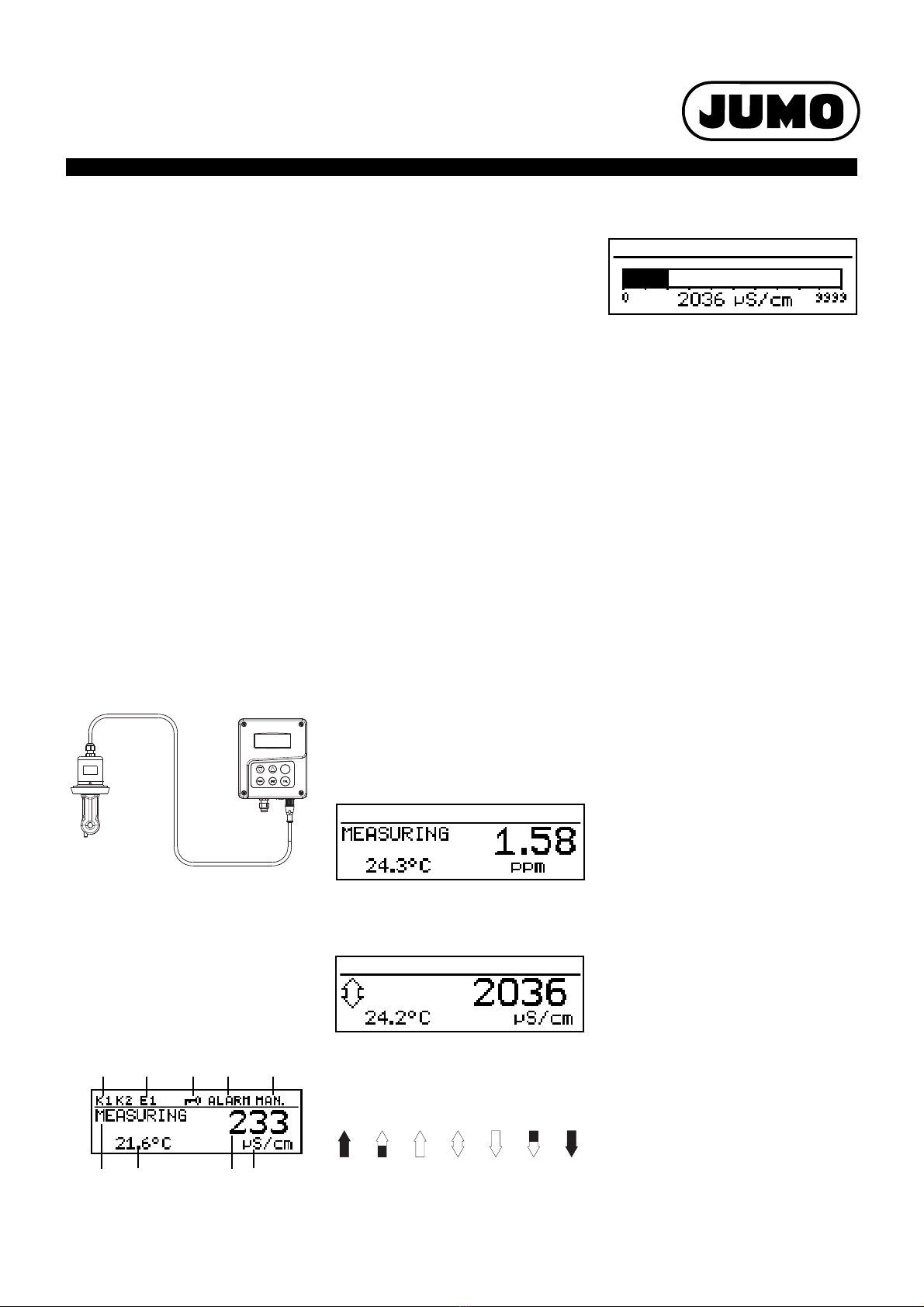
(3)Keyboard inhibited
(4)Alarm has been activated
(5)Instrument is in manual mode
(6)Instrument status
(7)Medium temperature
(8)Main measurement
(9)Unit of main measurement
The user can specify what is to appear in
positions (7) and (8) of the display:
-Nodisplay
- Corrected or uncorrected measurement
-Temperature
- Output level 1 or 2
-Setpoint1or2
Operation
To make programming and operation easy, all
parameters are clearly assigned to levels and
displayed in plain text. Operation is protected
by a code word. Operation can be adapted on
an individual basis because parameters can
be generally enabled or assigned to the
protected area.
A setup program for the PC is available as a
more convenient configuration option, rather
than using the instrument keyboard.
Display modes
Three display modes are available:
Large numbers
Here the measurements are displayed in
numbers, as usual.
Trend display
Here the numerical value is supplemented by
a symbol to indicate the direction and speed
of change for the measurement.
This can be very useful when the controller is
being optimized, for example.
from left to right:
fast, medium and slow rise,
steady,
slow, medium and fast fall.
Functional description
The instrument is designed for on-site use. A
robust housing protects the electronics and
electrical connections against aggressive
environmental conditions (IP67). As an
alternative, the instrument can also be
installed in a panel; the front then has IP65
enclosure protection. Easily installed screw
connectors are used for electrical connection.
A ventilation screw with a PTFE membrane
prevents condensation buildup.
Transmitter
The transmitter receives the measurement
signal from the inductive measuring cells of
the JUMO tecLINE Ci series, see data sheet
202941.
With the inductive measurement method,
acquisition of specific conductivity is largely
maintenance-free, even in the most difficult of
medium conditions. Unlike the conductive
measurement method, there are practically no
problems such as electrode breakdown and
polarization.
By acquiring the temperature of the sample
medium, the instrument can automatically
perform temperature compensation.
Components of the measurement
chain
Displays and controls
(1)Switching output 1 or 2 is active
(2)Binary input 1 is triggered
(1) JUMO tecLine Ci, inductive
conductivity and temperature sensor
(2) Cable
(JUMO tecLine Ci component)
(3) JUMO AQUIS 500 Ci, transmitter/
controller for conductivity,
concentration and temperature
(1) (2)
(3)
(1) (2) (4) (5)
(6) (7) (8) (9)
(3)
Bar graph
In this display mode, it only takes a glance to
ascertain the range for the current
measurement.
Any scale can be used for the bar graph.
Function modes
Electrolytic conductivity
µS/cm or mS/cm are the units used for
display and control.
Concentration measurement
Caustic soda
NaOH0 to 12 % by weight
NaOH25 to 50 % by weight
Nitric acid
HNO30to25%byweight
HNO336 to 82 % by weight
Sulphuric acid
H2SO40to28%byweight
H2SO436 to 85 % weight
H2SO492 to 99 % by weight
Hydrochloric acid
HCl 0 to 18 % by weight
HCl22 to 44 % by weight
Customized table
In this mode, the input value (specific
conductivity) can be displayed in accordance
with a table (max. 20 value pairs). This
function can be used to implement simple
concentration measurements, for example.
Table values can only be entered using the
optional setup program.
Calibration
Cell constant
Because of manufacturing constraints, the
cell constant of a conductivity measuring cell
may differ slightly from its nominal value.
Wear or the accumulation of deposits during
operation can also cause the cell constant to
change. This changes the output signal from
the measuring cell. With this instrument, the
user has the opportunity to compensate for
deviations in the nominal value of the cell
constant by manual input, or by automatic
calibration of the relevant cell constant.
Installation factor
This parameter can be used to compensate
for unfavorable sensor mounting conditions.
Temperature coefficient
The conductivity of virtually all solutions is
temperature dependent. To ensure correct
measurement therefore, both the temperature
and the temperature coefficient a [%/C] of the
measurement solution must be known. The
temperature can either be measured
automatically with a Pt 100 or Pt 1000
temperature probe, or the user must set the

JUMO GmbH & Co. KG
Delivery address: Mackenrodtstraße 14
36039 Fulda, Germany
Postal address:
36035 Fulda, Germany
Phone: +49 661 6003-0
Fax: +49 661 6003-607
Email: [email protected]
Internet: www.jumo.net
JUMO Instrument Co. Ltd.
JUMO House
Temple Bank, Riverway
Harlow, Essex CM20 2DY, UK
Phone: +44 1279 635533
Fax: +44 1279 635262
Email: [email protected]
Internet: www.jumo.co.uk
JUMO Process Control, Inc.
6733 Myers Road
East Syracuse, NY 13057, USA
Phone: 315-437-5866
1-800-554-5866
Fax: 315-437-5860
Email: [email protected]
Internet: www.jumousa.com
V1.00/EN/00520247
Page 3/12Data Sheet 202566
temperature by hand.
The temperature coefficient can be
automatically determined by the instrument,
or it can be entered by hand.
Calibration logbook
The last five successful calibrations can be
accessed in the calibration logbook. This
allows the ageing of the connected sensor to
be assessed.
Calibration timer
The calibration timer indicates (on request) a
required routine calibration. The calibration
timer is activated by entering the number of
days that must expire before there is a
scheduled re-calibration (specified by the
system or the operator).
Min/max value memory
This memory records the minimum and
maximum input quantities that occur. This
information can be used, for example, to
assess whether the design of the connected
sensor is suitable for the values that actually
occur.
Binary input
The following functions can be accessed
through the binary input:
- Key inhibit activation
When this function is activated, operation
is no longer possible via the keyboard.
- "HOLD" mode activation
When this function is activated, the
outputs (analog and relay) adopt the
states previously defined.
- Alarm suppression (controller alarm only)
With this function, it is possible to
temporarily deactivate alarm generation
via the relevantly configured relay.
The predefined function is activated using a
floating contact (such as a relay) to bridge the
relevant terminals.
Control functions
Functions that are configured by parameters
can be assigned to the relay. P, PI, PD and
PID structures can be freely programmed as
control functions.
Relay outputs
Two relay changeover contacts are available
for the main measurement variable and/or the
temperature.
The following functions can be programmed:
- Switching direction
(min/max)
- Limit controller
(switch-on/switch-off delay, hysteresis)
- Pulse width output
(see Control functions)
- Pulse frequency output
(see Control functions)
- Modulating function
(see Control functions)
- Alarm functions
(switch-on/switch-off delay, hysteresis)
- Pulse controls
With this function, the output briefly
switches on when the switching point is
reached and then switches off again
-Alarm
- Sensor/range error
- Behavior in the event of an alarm,
underrange or overrange measurement,
calibration and "HOLD"
Contact functions
Alarm function AF 7 left (max.)
Alarm function AF 8 right (min.)
Window alarm function AF 1 left
Window alarm function AF 2 right
Pulse contact
Triggering condition longer than pulse
duration
AL
HySt
ON
Measurement value
AL
HySt
ON
Measurement value
AL
wMeasurement value
ON
HySt
w
HySt AL
ON
Measurement value
Time
On
Off
Pulse duration
Pulse
contact
Time
On
Off
Triggering
condition
Analog outputs
There are up to 2 analog outputs available.
The following functions can be selected:
With the analog process value output, the range start and end values are freely selectable.
The response of the outputs to over/underrange, alarm and calibration is freely programmable.
Simulation function: The analog process value outputs can be freely set in the manual ("Hand")
mode.
Application: "Dry run" start-up of the plant, troubleshooting, servicing.
Output Analog process value output Continuous controller
main value
Main variable Temperature
1X-X
2-XX

JUMO GmbH & Co. KG
Delivery address: Mackenrodtstraße 14
36039 Fulda, Germany
Postal address:
36035 Fulda, Germany
Phone: +49 661 6003-0
Fax: +49 661 6003-607
Email: [email protected]
Internet: www.jumo.net
JUMO Instrument Co. Ltd.
JUMO House
Temple Bank, Riverway
Harlow, Essex CM20 2DY, UK
Phone: +44 1279 635533
Fax: +44 1279 635262
Email: [email protected]
Internet: www.jumo.co.uk
JUMO Process Control, Inc.
6733 Myers Road
East Syracuse, NY 13057, USA
Phone: 315-437-5866
1-800-554-5866
Fax: 315-437-5860
Email: [email protected]
Internet: www.jumousa.com
V1.00/EN/00520247
Page 4/12Data Sheet 202566
Pulse contact
Triggering condition shorter than pulse
duration
Pulse width controller
(output active with X > W and control
structure P)
If actual value X exceeds setpoint W, the P
controller will control in proportion to the
control deviation. When the proportional band
is exceeded, the controller operates with an
output level of 100 % (100 % clock ratio).
Pulse frequency controller
(output active with X > W and control
structure P)
If actual value X exceeds setpoint W, the P
controller will control in proportion to the
control deviation. When the proportional band
is exceeded, the controller operates with an
output level of 100 % (maximum switching
frequency).
Time
On
Off
Pulse duration
Pulse
contact
Time
On
Off
Triggering
condition
Actual value X
Setpoint W
Proportional band XP
100%
50%
0%
Output level y
Switching period
10%
90% 90%
10%
t
On
50%
50%
t
Off
10%
90%
X
P
X - W
01
100%
50%
0% no pulses
50% pulse frequency
maximum pulse frequency
Setpoint W
Proportional band X
P
X
P
X - W
01
Output level y
Actual value X
Technical data
Main input conductivity
Secondary input temperature
Temperature compensation
Measuring range 0000 to 9999 µS/cm
0.000 to 9.999 mS/cm
0.00 to 99.99 mS/cm
0.0 to 999.9 mS/cm
0 to 2000 mS/cm
Accuracya
0.000 to 1.000 mS/cm
1.01 to 500 mS/cm
501 to 2000 mS/cm
aTemperature error at JUMO AQUIS 500 Ci with inductive conductivity probe
JUMO tecLINE Ci. Deviation of 22 °C relative to the output signal end value 0(4) to 20 mA
and 0 to 10 V.
1.5 % of the measuring range
1 % of the measuring range
1.5 % of the measuring range
Operating mode
Concentration measurement
NaOH caustic solution
HNO3nitric acid
H2SO4sulphuric acid
HCL hydrochloric acid
Range 1: 0 to 12 % by weight
Range 2: 20 to 50 % by weight
Range 1: 0 to 25 % by weight
Range 2: 36 to 82 % by weight
Range 1: 0 to 28 % by weight
Range 2: 36 to 85 % by weight
Range 3: 92 to 99 % by weight
Range 1: 0 to 18 % by weight
Range 2: 22 to 44 % by weight
Operating mode
Customized table
The compensated conductivity is converted to a new
display value by means of a table. The table can contain
as many as 29 value pairs.
The display unit can also be adapted.
Process sequence:
Uncompensated conductivity > Temperature
compensation > Linearization with table > Display value.
Pt100 (automatic detection)
Measuring range
Accuracy
Ambient temperature error
-50 to 250 °C
±0,5 K up to 100 °C, ±0,8 K as of 100 °C
0.05 %/10 °C
Pt1000 (automatic detection)
Measuring range
Accuracy
Ambient temperature error
-50 to 250 °C
±0,5 K up to 100 °C, ±1,0 K as of 100 °C
0.05 %/10 °C
NTC / PTC
Measuring range
Accuracy
Ambient temperature error
max. 4 kΩ
Table input with up to 20 value pairs via setup program
≤0.3 °C (dependent on interpolation points)
0.05 %/10 °C
Linear
TC (α) setting range
Temperature range
0 to 5.5 %/C
0(to10) to 100 °C
Natural water (ISO 7888)
TC (α) setting range
Temperature range
n/a
0to36°C
Reference temperature adjustable: 15 to 30 °C
preset to 25 °C (standard)

JUMO GmbH & Co. KG
Delivery address: Mackenrodtstraße 14
36039 Fulda, Germany
Postal address:
36035 Fulda, Germany
Phone: +49 661 6003-0
Fax: +49 661 6003-607
Email: [email protected]
Internet: www.jumo.net
JUMO Instrument Co. Ltd.
JUMO House
Temple Bank, Riverway
Harlow, Essex CM20 2DY, UK
Phone: +44 1279 635533
Fax: +44 1279 635262
Email: [email protected]
Internet: www.jumo.co.uk
JUMO Process Control, Inc.
6733 Myers Road
East Syracuse, NY 13057, USA
Phone: 315-437-5866
1-800-554-5866
Fax: 315-437-5860
Email: [email protected]
Internet: www.jumousa.com
V1.00/EN/00520247
Page 5/12Data Sheet 202566
Measuring circuit monitoring
Cell constant
Binary input
Controller
Analog outputs (max. 2)
Switching outputs (max. two (SPDT) changeovers)
Setup interface
Conductivity input
Overrange
Short circuit
Broken lead
yes
dependent on range
dependent on range
Temperature input
Overrange/underrange
Short circuit
yes
yes
Adjustment range 1
Adjustment range 2
4to6[1/cm]
6to8[1/cm]
Setting range of the
relative cell constant
80 to 120 %
Installation factor 80 to 120 %
Activation by floating contact
Function key inhibit
HOLD
alarm suppression
Controller type alarm functions, limit controllers, pulse width controllers, pulse frequency controllers,
modulating controllers, continuous controllers
Controller structure P/PI/PD/PID
A/D converter dynamic resolution up to 14 bits
Sampling time 500 ms
Output type Signal range Accuracy Temperature error Permissible
load resistance
Current signal 0/4 to 20 mA ≤0.25 % 0.08 %/10 °C ≤500 Ω
Voltage signal 0 to 10 V ≤0.25 % 0.08 %/10 °C ≥500 Ω
The analog outputs respond in accordance with NAMUR recommendation NE43.
The analog outputs are electrically isolated, AC 30 V/DC 50 V.
Rated load AC 3 A/250 V (resistive load)
Contact life >2x10⁵operations at rated load
Interface for configuring the instrument with the available setup program option
(for instrument configuration only).

JUMO GmbH & Co. KG
Delivery address: Mackenrodtstraße 14
36039 Fulda, Germany
Postal address:
36035 Fulda, Germany
Phone: +49 661 6003-0
Fax: +49 661 6003-607
Email: [email protected]
Internet: www.jumo.net
JUMO Instrument Co. Ltd.
JUMO House
Temple Bank, Riverway
Harlow, Essex CM20 2DY, UK
Phone: +44 1279 635533
Fax: +44 1279 635262
Email: [email protected]
Internet: www.jumo.co.uk
JUMO Process Control, Inc.
6733 Myers Road
East Syracuse, NY 13057, USA
Phone: 315-437-5866
1-800-554-5866
Fax: 315-437-5860
Email: [email protected]
Internet: www.jumousa.com
V1.00/EN/00520247
Page 6/12Data Sheet 202566
Electrical data
Display
Housing
Approvals/approval marks
Power supply AC 110 to 240 V; -15/+10 %; 48 to 63 Hz
AC/DC20to30V;48to63Hz
DC 12 to 24 V; +/-15 % (permissible only for connection to SELV/PELV circuits)
Power consumption approx. 14 VA
Electrical safety EN 61 010, Part 1
overvoltage category IIIa, pollution degree 2
aNot valid for power supply 30, DC 12 to 24 V
Data backup EEPROM
Electrical connection
Power supply, relay outputs,
sensor inputs
Analog outputs
Inductive conductivity sensor
Pluggable screw terminals, conductor cross-section max. 2.5 mm2
Pluggable screw terminals, conductor cross-section max. 1.5 mm2
M12 connection
Graphic LC display 120 x 32 pixels
Backlighting Programmable:
- off
- on for 60 seconds during operation
Material ABS
Cable entry Cable glands, max. 2 x M16 and 2 x M12
Feature Venting element to prevent condensation
Ambient temperature range
(the specified accuracy is adhered
to in this range)
-10 to +50 °C
Operating temperature range
(instrument operational)
-15 to +65 °C
Storage temperature range -30 to +70 °C
Climatic rating Rel. humidity ≤90 % annual mean, no condensation
(based on EN 60721 3-3 3K3)
Enclosure protection
to EN 60529
Surface-mounted housing:IP67
Control cabinet mounting:at front IP65, at rear IP20
Vibration resistant to EN 60068-2-6
Weight Surface-mounted housing:approx. 900 g
Control cabinet mounting:approx. 480 g
Dimensions See dimensioned drawings on page 10
Mark of confirmity Testing laboratory Certifikates/certification numbers Test basis valid for
c UL us Underwriters Laboratories E 201387 UL 61010-1 all versions

JUMO GmbH & Co. KG
Delivery address: Mackenrodtstraße 14
36039 Fulda, Germany
Postal address:
36035 Fulda, Germany
Phone: +49 661 6003-0
Fax: +49 661 6003-607
Email: [email protected]
Internet: www.jumo.net
JUMO Instrument Co. Ltd.
JUMO House
Temple Bank, Riverway
Harlow, Essex CM20 2DY, UK
Phone: +44 1279 635533
Fax: +44 1279 635262
Email: [email protected]
Internet: www.jumo.co.uk
JUMO Process Control, Inc.
6733 Myers Road
East Syracuse, NY 13057, USA
Phone: 315-437-5866
1-800-554-5866
Fax: 315-437-5860
Email: [email protected]
Internet: www.jumousa.com
V1.00/EN/00520247
Page 7/12Data Sheet 202566
Electrical connection
Connection Terminal Row
Inputs
Power supply for transmitter/controller
Power supply (23): AC 110 to 240 V, +10 %/-15 %, 48 to 63 Hz
Power supply (25): AC/DC 20 to 30 V, 48 to 63 Hz
Power supply (30): DC 12 to 24 V, ± 15 %
1 N (L-)
2 L1 (L+)
1
NC 3
Do not change this wiring!
Only JUMO tecLINE Lf Ci inductive conductivity cells must be operated
at the M12 connector, see data sheet 202941!
1
2
3
4
5
6
7
8
9
2
Resistance thermometer in 2-wire circuit 8
9
10
Resistance thermometer in 3-wire circuit 8
9
10
Binary input 11
12
Row 1
Row 2
987654103
NL1
(L-) (L+)
13 14 15 16
9876541032
111 12
The JUMO AQUIS 500 Ci power supply is connected at the
row 1 terminals.
The row 2 terminals are factory-wired for connecting a
JUMO tecLINE Lf Ci inductive conductivity cell.
1
4
2
3
7
6
5
8
9
ϑ
9
8
10
11
12

JUMO GmbH & Co. KG
Delivery address: Mackenrodtstraße 14
36039 Fulda, Germany
Postal address:
36035 Fulda, Germany
Phone: +49 661 6003-0
Fax: +49 661 6003-607
Email: [email protected]
Internet: www.jumo.net
JUMO Instrument Co. Ltd.
JUMO House
Temple Bank, Riverway
Harlow, Essex CM20 2DY, UK
Phone: +44 1279 635533
Fax: +44 1279 635262
Email: [email protected]
Internet: www.jumo.co.uk
JUMO Process Control, Inc.
6733 Myers Road
East Syracuse, NY 13057, USA
Phone: 315-437-5866
1-800-554-5866
Fax: 315-437-5860
Email: [email protected]
Internet: www.jumousa.com
V1.00/EN/00520247
Page 8/12Data Sheet 202566
Outputs
Analog output 1
0to20mAand20to0mAor4to20mAand20to4mA
or
0 to 10 V and 10 to 0 V (electrically isolated)
+ 13
- 14
2
Analog output 2
0to20mAand20to0mAor4to20mAand20to4mA
or
0 to 10 V and 10 to 0 V (electrically isolated)
+ 15
- 16
Switching output K1 (floating) 4 pole
5 NC
6 NO
1NC 7
Switching output K2 (floating) 8 pole
9 NC
10 NO
Connection Terminal Row
6
4
5
10
8
9

JUMO GmbH & Co. KG
Delivery address: Mackenrodtstraße 14
36039 Fulda, Germany
Postal address:
36035 Fulda, Germany
Phone: +49 661 6003-0
Fax: +49 661 6003-607
Email: [email protected]
Internet: www.jumo.net
JUMO Instrument Co. Ltd.
JUMO House
Temple Bank, Riverway
Harlow, Essex CM20 2DY, UK
Phone: +44 1279 635533
Fax: +44 1279 635262
Email: [email protected]
Internet: www.jumo.co.uk
JUMO Process Control, Inc.
6733 Myers Road
East Syracuse, NY 13057, USA
Phone: 315-437-5866
1-800-554-5866
Fax: 315-437-5860
Email: [email protected]
Internet: www.jumousa.com
V1.00/EN/00520247
Page 9/12Data Sheet 202566
Dimensions
Panel mounting/drilling diagram
30
60
149
134
120
161
140
77 94
94
23
Note:
1. Attach template to panel.
2. Drill holes ( 4.5 mm and 10 mm)
3. Cut out the section within the marking
lines.
4. Deburr
To ensure enclosure protection (see data
sheet), the panel must be sufficiently
stable.
øø
ø 4.5
ø 10
100.5
108.6
120.5
121.6
44.2
Note:
The drilling template is shown actual size in
operating manual B 202566.0.

V1.00/EN/00520247
Page 10/12Data Sheet 202566
JUMO GmbH & Co. KG
Delivery address: Mackenrodtstraße 14
36039 Fulda, Germany
Postal address:
36035 Fulda, Germany
Phone: +49 661 6003-0
Fax: +49 661 6003-607
Email: [email protected]
Internet: www.jumo.net
JUMO Instrument Co. Ltd.
JUMO House
Temple Bank, Riverway
Harlow, Essex CM20 2DY, UK
Phone: +44 1279 635533
Fax: +44 1279 635262
Email: [email protected]
Internet: www.jumo.co.uk
JUMO Process Control, Inc.
6733 Myers Road
East Syracuse, NY 13057, USA
Phone: 315-437-5866
1-800-554-5866
Fax: 315-437-5860
Email: [email protected]
Internet: www.jumousa.com
Accessories
1The suspension fitting comprises a holder for suspension fitting 00453191 (see Accessories) and a measuring cell with a suitable fitting
(see data sheet 202922, for example):

JUMO GmbH & Co. KG
Delivery address: Mackenrodtstraße 14
36039 Fulda, Germany
Postal address:
36035 Fulda, Germany
Phone: +49 661 6003-0
Fax: +49 661 6003-607
Email: [email protected]
Internet: www.jumo.net
JUMO Instrument Co. Ltd.
JUMO House
Temple Bank, Riverway
Harlow, Essex CM20 2DY, UK
Phone: +44 1279 635533
Fax: +44 1279 635262
Email: [email protected]
Internet: www.jumo.co.uk
JUMO Process Control, Inc.
6733 Myers Road
East Syracuse, NY 13057, USA
Phone: 315-437-5866
1-800-554-5866
Fax: 315-437-5860
Email: [email protected]
Internet: www.jumousa.com
V1.00/EN/00520247
Page 11/12Data Sheet 202566
Order details:JUMO AQUIS 500 Ci
(1) Basic type
202566 JUMO AQUIS 500 Ci - transmitter/controller for inductive conductivity, concentration and temperature
(2) Basic type extension
10 for panel mounting
20 in surface-mounted housing
(3) Output 1 (for main value or continuous controller)
000 no output
888 analog output 0(4) to 20 mA and 0 to 10 V
(4) Output 2 (for temperature or continuous controller)
000 no output
888 analog output 0(4) to 20 mA and 0 to 10 V
(5) Output 3
000 no output
310 relay with changeover contact
(6) Output 4
000 no output
310 relay with changeover contact
(7) Power supply
23 AC 110 to 240 V, +10 %/-15 %, 48 to 63 Hz
25 AC/DC 20 to 30 V, 48 to 63 Hz
30 DC 12 to 24 V, ± 15 %
(8) Extra codes
000 none
(1) (2) (3) (4) (5) (6) (7) (8)
Order code /-----/,...
Order example 202566 / 20 - 888 - 000 - 310 - 000 - 23 / 000

JUMO GmbH & Co. KG
Delivery address: Mackenrodtstraße 14
36039 Fulda, Germany
Postal address:
36035 Fulda, Germany
Phone: +49 661 6003-0
Fax: +49 661 6003-607
Email: [email protected]
Internet: www.jumo.net
JUMO Instrument Co. Ltd.
JUMO House
Temple Bank, Riverway
Harlow, Essex CM20 2DY, UK
Phone: +44 1279 635533
Fax: +44 1279 635262
Email: [email protected]
Internet: www.jumo.co.uk
JUMO Process Control, Inc.
6733 Myers Road
East Syracuse, NY 13057, USA
Phone: 315-437-5866
1-800-554-5866
Fax: 315-437-5860
Email: [email protected]
Internet: www.jumousa.com
V1.00/EN/00520247
Page 12/12Data Sheet 202566
Stock versions (delivery 3 days after receipt of order)
Accessories (delivery 10 days after receipt of order)
Note
The following are required for the initial commissioning of the sensor and transmitter/controller or when replacing components:
- transmitter/controller e. g. JUMO AQUIS 500 Ci, data sheet 202566
- JUMO tecLine Ci inductive conductivity and temperature sensor, data sheet 202941
- Calibration adapter for inductive conductivity measurement, type 202711/21, data sheet 202711
Type Part no.
202566/20-888-888-310-310-23/000 00542691
Type Part no.
Protective roof for JUMO AQUIS 500a
aThe pipe installation set is needed for fitting the protective roof.
00398161
Pipe installation set for JUMO AQUIS 500b
bWith the pipe installation set, the JUMO AQUIS 500 can be attached to a pipe (e. g. a support pillar or a railing).
00483664
DIN rail installation set for JUMO AQUIS 500c
cWith the DIN rail installation set, the JUMO AQUIS 500 can be attached to a 35 mm x 7.5 mm DIN rail as per EN 60715 A.1.
00477842
Support pillar with base clamp, arm and chain 00398163
Holder for suspension fitting 00453191
Back panel set 202560/65/66/68 00506351
PC setup software 00483602
PC interface cable including USB/TTL converter and two adapters (USB connecting cable) 00456352
Calibration adapter for inductive conductivity measurement, type 202711/21 00543395
Table of contents
Other JUMO Transmitter manuals

JUMO
JUMO MIDAS S22 Ex User manual

JUMO
JUMO dTRANS T05 User manual

JUMO
JUMO CTI-500 Use and care manual

JUMO
JUMO dTRANS p02 DELTA User manual

JUMO
JUMO dTRANS O2 01 User manual

JUMO
JUMO CTI-500 User manual

JUMO
JUMO dTRANS T08 01 User manual

JUMO
JUMO dTRANS T06 User manual

JUMO
JUMO AQUIS 500 pH User manual

JUMO
JUMO HART dTRANS p20 Ex d User manual

JUMO
JUMO dTRANS T09 AS User manual

JUMO
JUMO DELOS SI User manual

JUMO
JUMO JUMO dTRANS p20 DELTA User manual

JUMO
JUMO JUMO dTRANS p20 DELTA User manual

JUMO
JUMO JUMO dTRANS p20 DELTA User manual

JUMO
JUMO dTRANS T03 Series User manual

JUMO
JUMO 907021/30 User manual

JUMO
JUMO CTI-750 User manual

JUMO
JUMO dTRANS T01 Junio User manual

JUMO
JUMO dTRANS T07 Reference guide