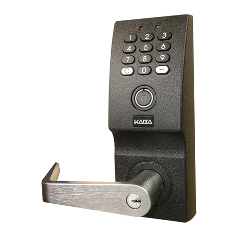
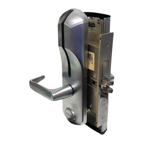
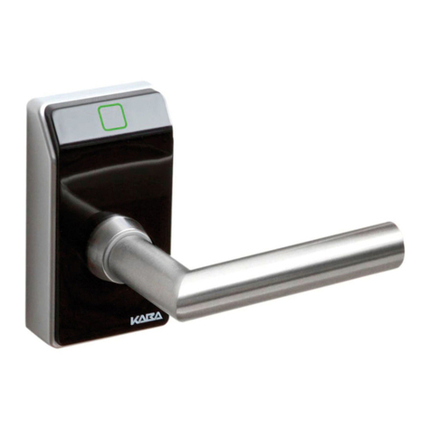
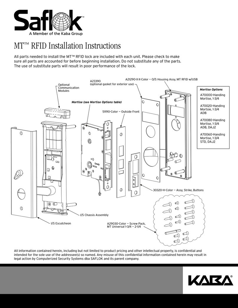
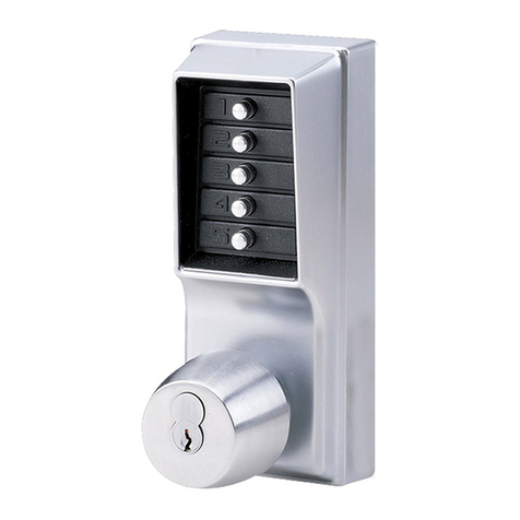
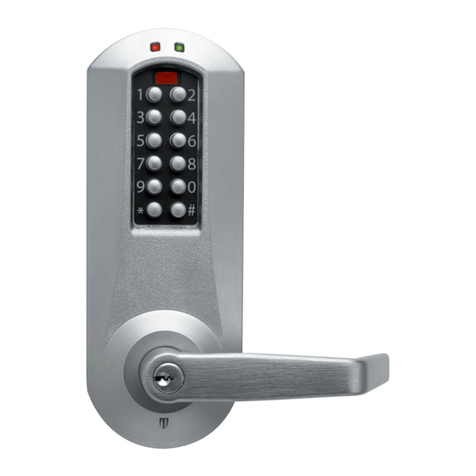
Kaba c-lever acc. EN1906 Cl.1 User manual

DE/EN/FR/IT
BEYOND SECURITY
Kaba c-lever acc. EN1906 Cl.1
Kurzanleitung
Quick Guide
Notice succincte
Istruzioni brevi
Doc.-No.: k2evo705xy-2013-09

Manufacturer:
Kaba GmbH
Ulrich-Bremi-Strasse 2
3130 Herzogenburg
AUSTRIA
www.kaba.com
Sales:
Kaba GmbH Kaba GmbH Kaba AG
Ulrich-Bremi-Strasse 2 Philipp-Reis-Strasse 14 Mühlebühlstrasse 23
3130 Herzogenburg 63303 Dreieich 8620 Wetzikon
AUSTRIA GERMANY SWITZERLAND
www.kaba.at www.kaba.de www. kaba.ch
Kaba Ltd Kaba S.A.S. Kaba S.r.l.
Lower Moor Way, Business Park 9, rue Pagès Via Andrea Costa, 6
Tiverton, Devon 92150 Suresnes 40013 Castell Maggiore (BO)
EX 16 6SS FRANCE ITALY
ENGLAND
www.kaba.co.uk www.kaba.fr www.kaba.it
This documentation may not be reproduced in any way nor further used in other ways without
written permission of Kaba AG.
Kaba® and Kaba elolegic® are registered trademarks of Kaba AG.
Copyright by Kaba AG 2013

Installation Kurzanleitung
Kaba c-lever nach EN1906 Kl.1 k2evo705xy-2013-09 3
DE
1 Außenschild mit Antenne
2 Innenschild
3 Kupplungseinheit
4 Befestigungsschraube für Drückerdorn
5 Drückerdorn
6 Innenbeschlag mit E-Modul
7 Befestigungsschraube (lt. Tabelle)
8 Batterieschutzfolie
9 Batterieprint
10 Batterie AA (2x im Gerät)
11 M6 Befestigungsschraube für Drücker
12 M6 Befestigungsschraube für Drücker
13 M3 Befestigungsschraube Innenschild
14 Schloss (nicht enthalten)
15 Antennenkabel
16 Schließzylinder (nicht enthalten)
17 Richtungsgeber
18 Stecker für Kupplungseinheit
19 Zentrierhülse
20 Oberer Ziehschutzscheibe
21 Unterlagsplatte
22 Schrauben für Unterlagsplatte
23 Distanzhülse Ø 12 x 11,3 mm
24 Distanzhülse Ø 9 x 9,3 mm
25 Untere Ziehschutzscheibe
115
24 21 22
18
11
3
4
5
620 7
2
14
16 12
25 13
810
9
23 19
ACHTUNG! Insbesondere bei direk-
ter, als auch indirekter, Berührung
von Leiterplatten können diese
durch elektrostatische Aufladung
beschädigt werden! Bei Montage-
und Wartungsarbeiten, immer ein
entsprechendes ESD-Erdungsband
verwenden!

4 k2evo705xy-2013-09 Kaba c-lever nach EN1906 Kl.1
DE
Kurzanleitung Installation
Vorhandenen Beschlag entfernen und mit-
gelieferte Schablone auf den Drückerdorn
aufstecken. Nach Ausrichten der Schab-
lone die Befestigungslöcher markieren.
HINWEIS: Bei einigen Drücker-
formen ist der Drückerdorn (5) an
die Türstärke anzupassen!
Schloss entfernen und die bereits ange-
zeichneten Befestigungslöcher bohren.
Nach dem Bohren die Späne entfernen
und das Schloss (14) wieder montieren.

Installation Kurzanleitung
Kaba c-lever nach EN1906 Kl.1 k2evo705xy-2013-09 5
DE
13
11
Richtungsgeber (17) so in die Kupplungs-
einheit einsetzen, dass bei Verwendung an
einer rechten Tür „R“ bzw. an einer linken
Tür „L“ von vorne zu lesen ist.
HINWEIS: Um das Einschieben des
Richtungsgebers (17) zu erleich-
tern, muss bei einer rechten Tür
der Vierkant der Kupplungseinheit
(3) gegen den Uhrzeigersinn und
bei einer linken Tür im Uhrzeiger-
sinn bis auf Anschlag gedreht wer-
den!
Die Kupplungseinheit (3) mit dem oberen
Teil voran in das Außenschild (1) schieben.
Danach den unteren Teil der Kupplungs-
einheit (3), unter Hilfenahme eines Schrau-
bendrehers, ebenfalls in das Außenschild
(1) schieben. Die Kupplungseinheit muß
fest und eben im Außenschild plaziert
sein! Kupplungseinheit (3) mit Stift-
schraube (11) befestigen.
HINWEIS: Laschen im Außen-
schild nicht verbiegen!

6 k2evo705xy-2013-09 Kaba c-lever nach EN1906 Kl.1
DE
Kurzanleitung Installation
23
4
24
18
11
5
21 22
15
19
Schließzylinder (16) in das Schloss ein-
schieben und nur gegen Verrutschen mit
der Zylinderschraube sichern (nicht fest-
schrauben).
Antennenkabel (15) durch die obere
Befestigungsbohrung auf die Türinnen-
seite führen und die Zentrierhülse (19) auf
die untere Gewindehülse schieben.
Danach das Außenschild (1) auf die Tür
aufstecken.
Um die Kupplungseinheit (3) zu entlas-
ten, muss nach dem Aufstecken des
Außenschildes (1) am Drückerdorn (5)
in Pfeilrichtung angezogen werden.
HINWEIS: Antennenkabel (15)
nicht quetschen!
HINWEIS:Beim Drückerdorn 7 mm
muss die Reduzierhülse so
eingebaut werden, dass die Frei-
stellung der Hülse nach oben zur
Stiftschraube (4) zeigt!
Den Drückerdorn (5) entsprechend
Schlossnuss auswählen und in den Vier-
kant der Kupplungseinheit (3) stecken,
danach Drückerdorn von oben mit
Gewindestift (4) befestigen. Kupplungs-
einheit (3) mit Stecker (18) verbinden und
in den Beschlag stecken. Anschließend die
Distanzhülse (23) über die untere Gewin-
dehülse und Distanzhülse (24) über die
obere Gewindehülse stecken!
Danach die Unterlagsplatte (21) mit den
vier Befestigungsschrauben für Unterlags-
platte (22) am Aussenschild festschrauben!
ACHTUNG! Auf das Kabel achten!

Installation Kurzanleitung
Kaba c-lever nach EN1906 Kl.1 k2evo705xy-2013-09 7
DE
Schraubenpack
obere / untere
Befestigungsschrauben
mittlere
Befestigungsschrauben
Dimension Türdicke Dimension Türdicke
Nr.1
Dorn 105 mm
für Türstärke
38 - 58 mm
M5 x 50 mm 38 - 44 mm M5 x 40 mm 38 - 40 mm
M5 x 45 mm 41 - 45 mm
M5 x 60 mm 45 - 54 mm M5 x 50 mm 46 - 50 mm
M5 x 55 mm 51 - 55 mm
M5 x 70 mm 55 - 58 mm M5 x 60 mm 56 - 58 mm
Nr.2
Dorn 120 mm
für Türstärke
58 - 73 mm
Dorn 155 mm
für Türstärke
73 - 100 mm
M5 x 70 mm 56 - 64 mm M5 x 60 mm 59 - 60 mm
M5 x 80 mm 65 - 74 mm M5 x 65 mm 61 - 65 mm
M5 x 70 mm 66 - 70 mm
M5 x 90 mm 75 - 84 mm M5 x 75 mm 71 - 75 mm
M5 x 80 mm 76 - 80 mm
M5 x 100 mm 85 - 94 mm M5 x 85 mm 81 - 85 mm
M5 x 90 mm 86 - 90 mm
M5 x 110 mm 95 - 100 mm M5 x 95 mm 91 - 95 mm
M5 x 100 mm 96 - 100 mm
Innenbeschlag (6) auf Drückerdorn (5) und
Zylinder (16) aufstecken. Anschließend
den Innenbeschlag (6) mit den drei Befes-
tigungsschrauben (7) mit dem Außen-
schild (1) festschrauben.
Anzugsdrehmoment: 2,5 ±0,5 Nm
Um die Ziehsicherheit zu gewährleisten,
müssen bei der oberen Befestigungs-
schraube die obere Ziehschutzscheibe
(20) und bei der unteren Befestigungs-
schraube die untere Ziehschutzscheibe
(25) beigelegt werden. Kabel (15) in den
dafür vorgesehenen Stecker am E-Modul
des Innenbeschlags (6) anstecken.
HINWEIS: Mindesteinschraubtiefe
der mittleren Schraube ist 8 mm.
HINWEIS: Bei Türdicke 73- 85 mm muss der Dorn mit der Länge 155 mm gekürzt
werden!
20
13
6
25

8 k2evo705xy-2013-09 Kaba c-lever nach EN1906 Kl.1
DE
Kurzanleitung Installation
Bei der c-lever Variante mit Breitschild
(55 mm), wird zur besseren Abstützung
des Innenschildes (2), zwischen dem
Innenbeschlag (6) und dem Innenschild
(2) eine Distanzscheibe beigelegt.
HINWEIS: Auf Polung der Batte-
rien achten!
Kontaktschutzfolie herausziehen.
Batterieschutzfolie zwischen die Batterien
stecken.
HINWEIS: An Türen zum Außenbe-
reich nur Lithium Batterien ver-
wenden!

Installation Kurzanleitung
Kaba c-lever nach EN1906 Kl.1 k2evo705xy-2013-09 9
DE
CLICK
Türstärke
door thickness
Schließzylinder (16) mit Zylinderschraube
befestigen.
HINWEIS: Zylinderüberstand
innen mindestens 18,5 mm und
aussen mindestens 23,5mm!
Innenschild (2) aufstecken und von unten
mit M3 Schraube (13) befestigen.
Zuletzt M6 Stiftschraube (12) in den Drü-
cker einschrauben.
HINWEIS: Batterietausch: Die M3
(unten) Schraube (13) entfernen,
Schraubendreher in die Senkung
der Schraube einführen und das
Innenschild anheben.

10 k2evo705xy-2013-09 Kaba c-lever nach EN1906 Kl.1
DE
Kurzanleitung Installation
Notöffnung mit Batterienotgerät: Batte-
rienotgerät mittels Programmierkabel an
die Programmierbuchse anstecken.
Berechtigtes User-Medium vor die
Antenne halten und den Knopf am Batte-
rienotgerät für ca. 1 Sekunde drücken.
Danach kann die Tür geöffnet werden.
ACHTUNG! Der Drücker bleibt so
lange eingekuppelt, bis die Batte-
rien gewechselt werden!

Installation Quick Guide
Kaba c-lever acc. EN1906 Cl.1 k2evo705xy-2013-09 11
EN
1 Outside shield with antenna
2 Inside shield
3 Coupling unit
4 Fastening screw for lever handle spindle
5 Lever handle spindle
6 Inside door furniture with e-module
7 Fastening screw (acc. to table)
8 Battery protection foil
9 Battery circuit board
10 AA batteries (2x inside device)
11 M6 fastening screw for lever handle
12 M6 fastening screw for lever handle
13 M3 fastening screw for inside shield
14 Mortise lock (not included)
15 Antenna cord
16 Lock cylinder (not included)
17 Direction pin
18 Socket for coupling unit
19 Centering sleeve
20 Upper pulling protection plate
21 Support plate
22 Screws for support plate
23 Distance sleeve Ø 12 x 11.3 mm
24 Distance sleeve Ø 9 x 9.3 mm
25 Lower pulling protection plate
115
24 21 22
18
11
3
4
5
620 7
2
14
16 12
25 13
810
9
23 19
ATTENTION! Printed circuit boards
can be damaged by electro static
discharge especially by direct con-
tact, but also by indirect contact.
Therefore, always wear a suitable
ESD earthing strap when installing
or repairing equipment!

12 k2evo705xy-2013-09 Kaba c-lever acc. EN1906 Cl.1
EN
Quick Guide Installation
Remove the existing door furniture and
put the drilling template (included) on the
lever handle spindle. After centering the
the template, mark the holes for the faste-
ning screws.
NOTE: For some lever handle
styles, adjust the lever handle spin-
dle to the door width.
Remove the mortise lock and drill holes for
the fastening screws at the drawn marks.
After drilling remove swarf and reinstall
the mortise lock (14).

Installation Quick Guide
Kaba c-lever acc. EN1906 Cl.1 k2evo705xy-2013-09 13
EN
13
11
Insert direction pin (17) into the coupling
unit so that the „R“ can be read from the
front on a right hand door and the „L“ on a
left hand door during use.
NOTE: For easy insertion of the
direction pin for right hand doors,
turn the square spindle of the cou-
pling unit counter-clockwise and
for left hand doors clockwise to the
stop.
Push the coupling unit (3) with top part
first into the outside shield (1). Afterwards
push the lower part of the coupling unit
(3) with help of a screwdriver into the
outershield (1) as well. The coupling unit
must be placed firmly and level into the
outside shield. Fasten the coupling unit (3)
with set screw (11).
NOTE: Do not bend the lash in the
outside shield!

14 k2evo705xy-2013-09 Kaba c-lever acc. EN1906 Cl.1
EN
Quick Guide Installation
23
4
24
18
11
5
21 22
15
19
Push the lock cylinder (16) into the mortise
lock and secure against movement with
the lock cylinder fastening screw (do not
screw tight).
Lead the antenna cord (15) through the
upper fastening bolt hole through the
door and push the centering sleeve (19)
over the lower threaded sleeve. After-
wards place the outer shield (1) on the
door. To relieve pressure on the coup-
ling unit (3), pull the lever handle
spindle (5) in the direction of the arrow
after putting the outside shield on the
door.
NOTE: Do not pinch the antenna
cord (15).
NOTE: For a spindle of 7 mm, the
reduction sleeve must be fitted
such that the release for the sleeve
is pointing upwards towards the
fixing screw (4)!
Select the lever handle spindle (5) accord-
ing to the mortise lock follower and insert
into the square of the coupling unit (3)
(see figure), afterwards handle spindle
fasten from above with threaded pin (4).
Connect the coupling unit (3) with the
plug (18) and push into the door furniture.
Afterwards put the distance sleeve (23)
over the lower threaded sleeve and dis-
tance sleeve (24) over the upper threaded
sleeve. Now firmly screw the support plate
(21) with four fastening screws (22) on the
outside shield.
ATTENTION: Take care of the cord.

Installation Quick Guide
Kaba c-lever acc. EN1906 Cl.1 k2evo705xy-2013-09 15
EN
screw pack
upper / lower
fastening screw
middle
fastening screw
dimension door width dimension door width
No.1
spindle105 mm
for door width
38 - 58 mm
M5 x 50 mm 38 - 44 mm M5 x 40 mm 38 - 40 mm
M5 x 45 mm 41 - 45 mm
M5 x 60 mm 45 - 54 mm M5 x 50 mm 46 - 50 mm
M5 x 55 mm 51 - 55 mm
M5 x 70 mm 55 - 58 mm M5 x 60 mm 56 - 58 mm
No.2
spindle
120 mm
for door width
58 - 73 mm
spindle
155 mm
for door width
73 - 100 mm
M5 x 70 mm 56 - 64 mm M5 x 60 mm 59 - 60 mm
M5 x 80 mm 65 - 74 mm M5 x 65 mm 61 - 65 mm
M5 x 70 mm 66 - 70 mm
M5 x 90 mm 75 - 84 mm M5 x 75 mm 71 - 75 mm
M5 x 80 mm 76 - 80 mm
M5 x 100 mm 85 - 94 mm M5 x 85 mm 81 - 85 mm
M5 x 90 mm 86 - 90 mm
M5 x 110 mm 95 - 100 mm M5 x 95 mm 91 - 95 mm
M5 x 100 mm 96 - 100 mm
Place the inside furniture (6) on the lever
handle spindle (59) and lock cylinder (16).
Fasten the inside furniture (6) with three
fastening- screws (7) with the outside
shield (1).
Tightening torque: 2.5 ±0.5 Nm
To ensure protection against pulling, ins-
tall the upper pulling protection plate (20)
under the upper fastening screw and the
lower pulling protection plate (25) under
the lower fastening screw.
Plug the cord (15) into the appropriate
receptacle on the inside shield (6).
NOTE: Minimum depth of the mid-
dle screw must be at least 8 mm.
HINWEIS: Spindles 155 mm long must be shortened for door width 73 - 85 mm!
20
13
6
25

16 k2evo705xy-2013-09 Kaba c-lever acc. EN1906 Cl.1
EN
Quick Guide Installation
The c-lever in the wide shield version
(55 mm) includes a distance sleeve which
is placed between the inside door furni-
ture (6) and the inside shield (2) to better
support the inside shield (2).
NOTE: Pay attention to the correct
position of the batteries.
Pull the contact protection film out.
Slide the battery protection foil between
the batteries.
NOTE: Only use lithium batteries
on doors in an outside environ-
ment.

Installation Quick Guide
Kaba c-lever acc. EN1906 Cl.1 k2evo705xy-2013-09 17
EN
CLICK
Türstärke
door thickness
Fasten the lock cylinder (16) with the
forend fastening screw.
NOTE: Cylinder stand off on the
inside 18.5 mm minimum and the
outside 23.5 mm minimum!
Snap on the inside shield (2) and fasten
with an M3 screw (13) from below.
Finally screw the M6 set screw (12) in the
lever handle.
NOTE: Replacing the batteries.
Remove the (lower) M3 screw, put
the screwdriver in the screw coun-
ter sink and lift off the inside shield
(2)!

18 k2evo705xy-2013-09 Kaba c-lever acc. EN1906 Cl.1
EN
Quick Guide Installation
Emergency opening with the emer-
gency battery device: Plug the emer-
gency battery device with the program-
ming cord to the programming receptacle.
Hold a valid user medium in front of the
antenna and press the button on the
emergency opening device for about 1
second. Afterwards the door can be ope-
ned.
ATTENTION! The lever handle
remains engaged until the batter-
ies have been replaced!

Installation Notice succincte
Kaba c-lever selon EN1906 Cl.1 k2evo705xy-2013-09 19
FR
1 Garniture extérieure avec antenne
2 Plaque intérieure
3 Module d‘accouplement
4 Vis de fixation pour broche de poignée
5Brochedepoignée
6 Garniture intérieure avec centre électro-
nique
7 Vis de fixation (selon tableau)
8 Film de protection des piles
9 Support de piles
10 Piles AA (2x en appareil)
11 Vis de fixation M6 pour poignée
12 Vis de fixation M6 pour poignée
13 Vis de fixation M3 pour garniture intéri-
eure
14 Serrure (non fournie)
15 Câble d‘antenne
16 Cylindre (non fournie)
17 Distributeur de direction
18 Prise pour module d‘accouplement
19 Douille de centrage
20 Discques de anti-arrachement supérieur
21 Plaque d‘assise
22 Vis pour plaque d‘assise
23 Douille d‘ecartement Ø 12 x 11,3 mm
24 Douille d‘ecartement Ø 9 x 9,3 mm
25 Discques de anti-arrachement inférieur
115
24 21 22
18
11
3
4
5
620 7
2
14
16 12
25 13
810
9
23 19
ATTENTION ! En cas de contact
direct ou indirect avec les circuits
imprimés, ceux-ci peuvent être
endommagés par une décharge
électrostatique ! Toujours utiliser un
ruban de mise à la terre ESD lors du
montage et/ou de la maintenance!

20 k2evo705xy-2013-09 Kaba c-lever selon EN1906 Cl.1
FR
Notice succincte Installation
Retirer la ferrure existante et placer le
gabarit fourni sur la broche de poignée.
Après voir positionné le gabarit, marquer
l'emplacement des trous de fixation.
NOTE: Pour certaines formes de
poignées, adapter la broche de
poignée (5) à l'épaisseur de la
porte!
Retirer la serrure et percer les trous de fixa-
tion aux emplacements marqués. Retirer
les copeaux de perçage et remonter la ser-
rure (14).
Table of contents
Languages:
Other Kaba Door Lock manuals

Kaba
Kaba c-lever 2662-K5 User manual

Kaba
Kaba LCLX User manual

Kaba
Kaba C-lever User manual

Kaba
Kaba Simplex 1000 Series Installation guide

Kaba
Kaba E-Flash EF780 User manual

Kaba
Kaba Ilco 790/79 Series User manual

Kaba
Kaba Simplex 1000 Series User manual

Kaba
Kaba E-PLEX 5X51 User manual

Kaba
Kaba E-Plex 5900 User manual

Kaba
Kaba S-module User manual

Kaba
Kaba PowerLever 1550 User manual
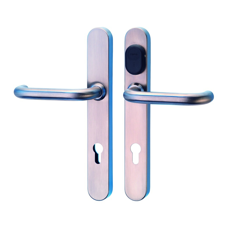
Kaba
Kaba E-Plex 5x00 Cylindrical User manual

Kaba
Kaba ILCO Generation E-760 Series User manual

Kaba
Kaba 7002 Series User manual

Kaba
Kaba E-Flash 680 User manual

Kaba
Kaba 1547-K5 User manual

Kaba
Kaba Peaks Preferred User manual

Kaba
Kaba C-lever User manual
Kaba
Kaba 7102 series User manual

Kaba
Kaba E30 User manual