Kemper 400F Support Wheel User manual

400F
Support Wheel
*OMKM113756*
OPERATOR'S MANUAL
400F Support Wheel
OMKM113756 ISSUE C8 (ENGLISH)
Maschinenfabrik Kemper GmbH & Co. KG
European Edition
PRINTED IN U.S.A.

Introduction
KM00321,0000419 -19-07APR15-1/1
Foreword
READ THIS MANUAL carefully to learn how to operate
and service your machine correctly. Failure to do so
could result in personal injury or equipment damage. This
support wheel may be installed and operated only on a
rotary harvesting unit. The user must be entitled to drive
a forage harvester on public roads. This manual and the
safety signs on the machine may also be available in other
languages (see your KEMPER dealer to order).
THIS MANUAL SHOULD BE CONSIDERED a permanent
part of your machine and must remain with the machine
when you sell it.
MEASUREMENTS IN THIS MANUAL are given in metric
units. The customary U.S. unit equivalents are also
quoted. Use only correct replacement parts and fasteners.
Metric and inch fasteners may require a specific metric
or inch wrench.
RIGHT-HAND AND LEFT-HAND sides are determined
by facing in the direction the implement will travel when
going forward.
LOADING AND HAULING of this support wheel must be
performed only by persons familiar with how the load is
secured, and who can provide evidence of this.
WRITE PRODUCT IDENTIFICATION NUMBERS (P.I.N.)
in the Specification or Identification Numbers section.
Accurately record all the numbers to help in tracing the
machine should it be stolen. Your KEMPER dealer needs
these numbers when you order parts. File the identification
numbers in a secure place away from machine.
BEFORE DELIVERING THIS MACHINE, your dealer
performed a predelivery inspection.
INTENDED USE: THIS SUPPORT WHEEL MUST BE
USED EXCLUSIVELY to transport 460plus, 475 and 475plus
rotary harvesting units.
Use in any other way is considered as contrary to the
intended use. The manufacturer accepts no liability for
damage or injury resulting from this misuse, and these
risks must be borne solely by the user.
THIS SUPPORT WHEEL MUST NOT be used to transport
rotary harvesting units other than those indicated in this
Operator's Manual, or to transport:
•Agricultural implements made by other manufacturers
•Any types of vehicle
Compliance with and strict adherence to the conditions
of operation, service and repair as specified by the
manufacturer also constitute essential elements for the
INTENDED USE.
THIS SUPPORT WHEEL MUST be serviced and repaired
ONLY by industrial mechanics, fitters or persons with
comparable qualifications. The accident prevention
regulations, all other generally recognized regulations
on safety and occupational medicine and the road traffic
regulations must be observed at all times. Any arbitrary
modifications carried out on this support wheel will relieve
the manufacturer of all liability for any resulting damage
or injury.
If you are not the first owner of this machine, it is in your
interest to contact your local KEMPER dealer to tell him
the serial number of this unit. This will help KEMPER to
inform you of relevant issues or product improvements.
031318
PN=2

Contents
Page
Predelivery Inspection
Checklist before Using for First Time ...........CLIST-1
Identification View
Identification View...............................................00-1
Safety Measures
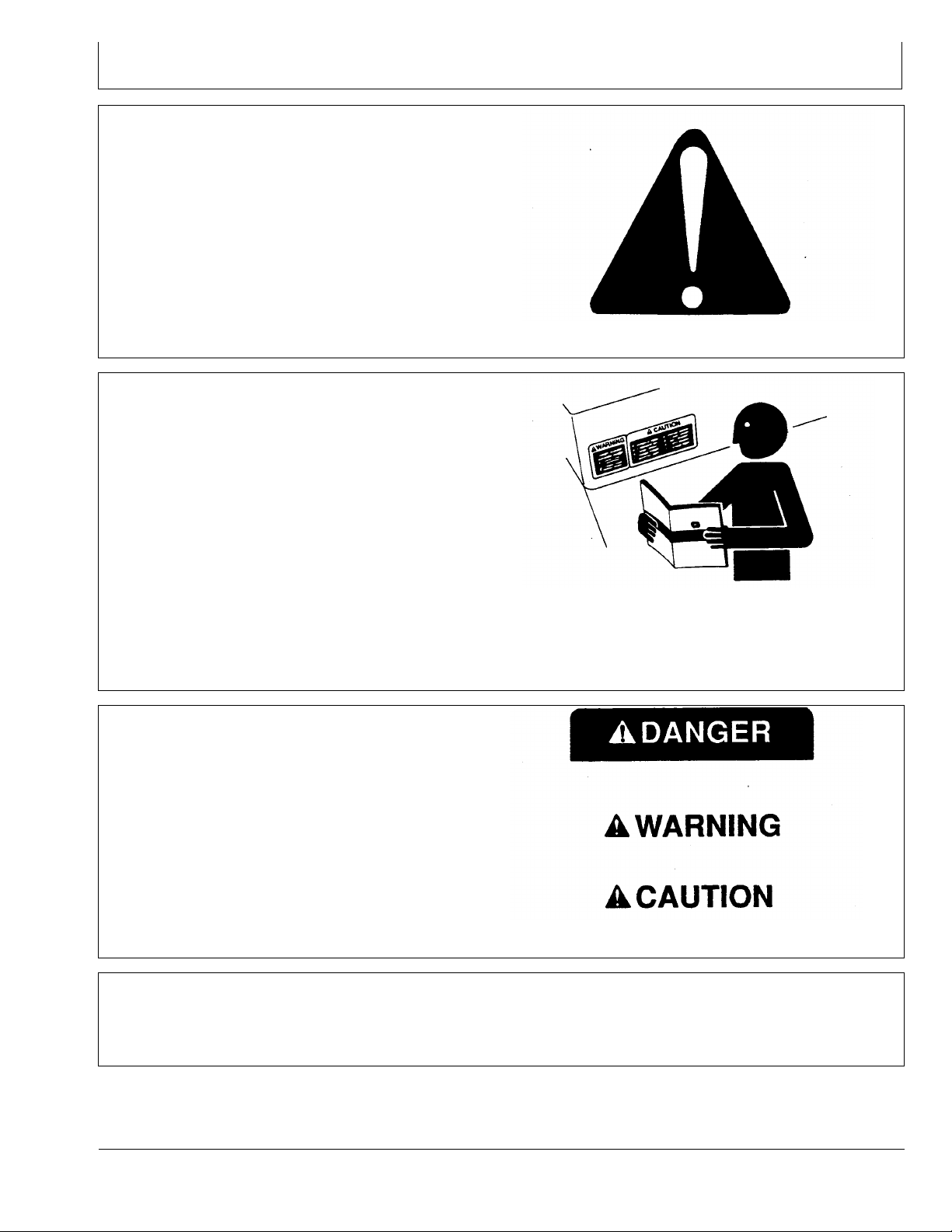
Recognize Safety Information ............................05-1
Follow Safety Instructions...................................05-1
Understand Signal Words...................................05-1
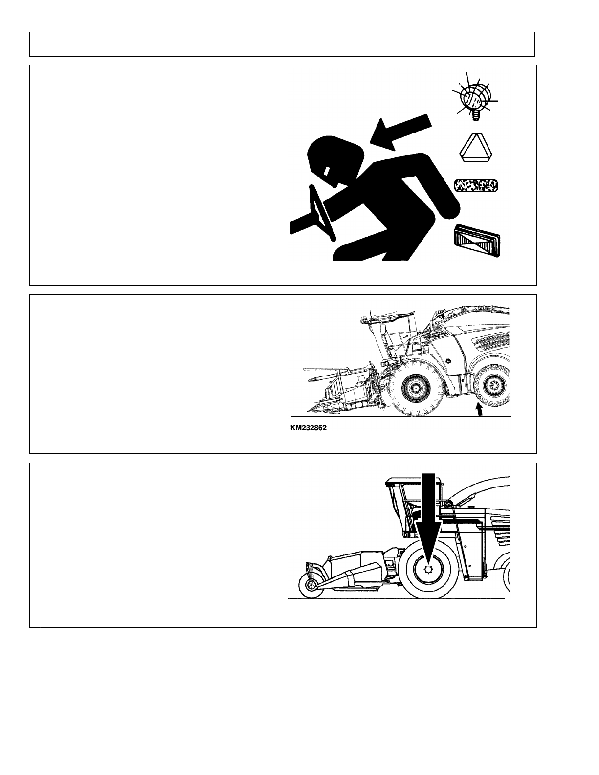
Check Machine Safety........................................05-1
Use Safety Lights and Devices...........................05-2
Ballasting for Safe Ground Contact....................05-2
Observe Maximum Permissible Front
Axle Load .......................................................05-2
Observe Road Traffic Regulations......................05-3
Prevent Machine Runaway.................................05-3
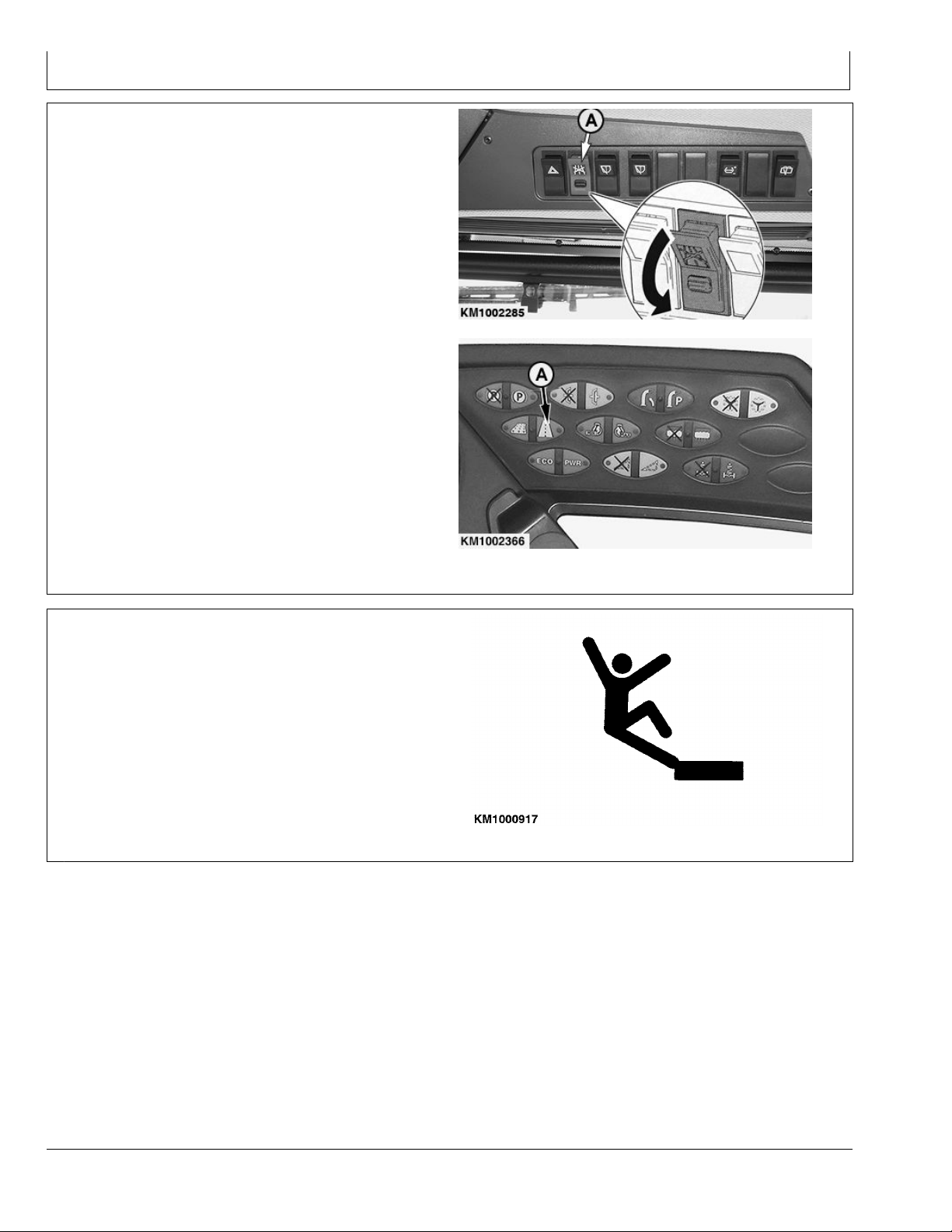
Switch for Road/Field Mode ...............................05-4
Danger of Falling ................................................05-4
Retighten Wheel Nuts.........................................05-5
Prepare for Emergencies....................................05-5
Wear Protective Clothing....................................05-5
Guards and Shields............................................05-6
Practice Safe Maintenance.................................05-6
Support Machine Properly..................................05-7
Remove Paint Before Welding or Heating..........05-7
Safety decals
Pictorial Safety Signs..........................................10-1
Replace Safety Signs .........................................10-1
Operator's Manual ..............................................10-1
Front Wheel Attaching Nuts................................10-2
Support Wheel....................................................10-2
Attaching
Ballasting the Forage Harvester.........................15-1
Prior to Attaching................................................15-1
Automatic Support Wheel Identification..............15-1
Attaching to a Rotary Harvesting Unit
with AHC (Option) ..........................................15-1
Unfold the Rotary Harvesting Unit ......................15-2
Attach Support Wheel.........................................15-2
Locking Device Position .....................................15-3
Adjust Locking Device (Only for Initial Use) .......15-3
Lock Support Wheel ...........................................15-3
Locking Status Indicator .....................................15-4
Page
Detaching
Detach Support Wheel .......................................20-1
Support Wheel Operation
Observe Maximum Permissible Front
Axle Load .......................................................25-1
Driving on Roads (Claas Forage Harvesters).....25-1
Driving on Roads (Fendt Forage Harvesters).....25-3
Locking Status Indicator .....................................25-6
Additional Weights
Additional Weights (Ballasting)...........................30-1
Ballasting chart (CLAAS forage harvesters).......30-1
Wheels
Service Tires Safely............................................35-1
Wheel Bolts and Nuts.........................................35-1
Tire Size .............................................................35-2
Tire Inflation Pressures.......................................35-2
Troubleshooting
400F Support Wheel...........................................40-1
Lubrication and Maintenance
Metric Bolt and Screw Torque Values.................45-1
Service Intervals.................................................45-1
Grease................................................................45-2
Every 10 Hours - Hook and Locking Devices .....45-2
Every 50 Hours - Wheel Nuts .............................45-2
Every 50 Hours - Wheel Bolts ............................45-3
Every 50 Hours - Swivel .....................................45-3
Every 50 Operating Hours—Wheel Hub.............45-3
Check the sensors and adjust them
(only rotary harvesting units for
Fendt forage harvesters)................................45-4
Technical specifications
400F Support Wheel...........................................50-1
EC Declaration of Conformity .............................50-1
Serial Number
Support Wheel Serial Number Plate...................55-1
Serial Number.....................................................55-1
Original Instructions. All information, illustrations and specifications in this
manual are based on the latest information available at the time of publication.
The right is reserved to make changes at any time without notice.
COPYRIGHT © 2018
John Deere GmbH & Co. KG Mannheim Regional Center
Zentralfunktionen
All rights reserved.
A John Deere ILLUSTRUCTION ™ Manual
i031318
PN=1

Contents
ii 031318
PN=2

Predelivery Inspection
KM00321,0000418 -19-31MAR15-1/1
Checklist before Using for First Time
Before using the support wheel for the first time, check
the following:
□Check the entire machine for loose or missing nuts and
screws.
□Before attaching the support wheel for the first time,
adjust the position of the locking device.
□Advise the customer of the proper weights and fluids
that must be used in the tires, depending upon forage
harvester.
□Check if all safety shields are in place and fastened
securely.
□Check for broken or damaged parts.
□Review the entire operator's manual with the customer
and stress the importance of proper and regular
lubrication and safety precautions.
(Signature of Technician) (Signature of Customer)
CLIST-1 031318
PN=5

Safety Measures
DX,ALERT -19-29SEP98-1/1
KM00321,000016B -19-14MAY09-1/1
DX,SIGNAL -19-03MAR93-1/1
FX,READY -19-28FEB91-1/1
Recognize Safety Information
This is a safety-alert symbol. When you see this symbol
on your machine or in this manual, be alert to the potential
for personal injury.
Follow recommended precautions and safe operating
practices.
T81389 —UN—28JUN13
Follow Safety Instructions
Carefully read all safety messages in this manual and on
your machine safety signs. Keep safety signs in good
condition. Replace missing or damaged safety signs. Be
sure new equipment components and repair parts include
the current safety signs. Replacement safety signs are
available from your KEMPER dealer.
Before you start working with the machine, learn how to
operate the machine and how to use controls properly. Do
not let anyone operate without instruction.
Keep your machine in proper working condition.
Unauthorized modifications to the machine may impair the
function and/or safety and affect machine life.
If you do not understand any part of this manual and need
assistance, contact your KEMPER dealer.
TS201 —UN—15APR13
Understand Signal Words
A signal word—DANGER, WARNING, or CAUTION—is
used with the safety-alert symbol. DANGER identifies the
most serious hazards.
DANGER or WARNING safety signs are located near
specific hazards. General precautions are listed on
CAUTION safety signs. CAUTION also calls attention to
safety messages in this manual.
TS187 —19—30SEP88
Check Machine Safety
Always check the road and general operating safety of
the machine before using.
05-1 031318
PN=7

Safety Measures
KM00321,000016C -19-14MAY09-1/1
KM00321,00003CB -19-12MAR15-1/1
KM00321,0000414 -19-30MAR15-1/1
Use Safety Lights and Devices
Prevent collisions with other road users. Slow moving
tractors with implements or drawn equipment, as well
as self-propelled machines are especially dangerous on
public roads. Always pay attention to traffic approaching
from behind, particularly when changing direction. Provide
for safe traffic conditions by using turn signals.
Use headlights, hazard warning lights, turn signals and
other safety devices according to the local regulations.
Keep safety devices in good condition. Replace missing
or damaged items.
TS951 —UN—12APR90
Ballasting for Safe Ground Contact
Operating, steering and braking performance of forage
harvester can be considerably affected by attachments
which alter the center of gravity of the machine. To
maintain safe ground contact, ballast the harvester at the
rear end as necessary. Observe the maximum permissible
axle loads and total weights.
KM232862 —UN—10FEB15
Observe Maximum Permissible Front Axle
Load
Transport of 475 und 475plus rotary harvesting units on
public roads with forage harvesters is only permissible
if the maximum front axle load of 11500 kg (25353 lb.)
is observed.
The maximum permissible front axle load can be observed
by attaching support wheel.
If the maximum permissible front axle load is not
observed, this will result in loss of permission to drive on
public roads and may cause serious personal injury and
machine damage.
KM1000915 —UN—29JUL09
05-2 031318
PN=8

Safety Measures
FX,ROAD -19-01MAY91-1/1
KM00321,00001C3 -19-29JUL09-1/1
Observe Road Traffic Regulations
Always observe local road traffic regulations when using
public roads.
H28930 —UN—30JUN89
Prevent Machine Runaway
Avoid possible injury or death from machine runaway.
Do not park machine on a slope; otherwise take
precautions to prevent it from rolling away.
KM1000916 —UN—29JUL09
05-3 031318
PN=9

Safety Measures
KM00321,000021D -19-01OCT13-1/1
KM00321,00001C5 -19-29JUL09-1/1
Switch for Road/Field Mode
When driving on roads, the switch for road/field mode (A)
must be in the position for road travel.
This ensures that all the hydraulic functions with the
exception of the steering and the return to pressure are
switched off.
A—Switch for Road/Field Mode
KM1002285 —UN—27FEB18
Claas Forage Harvesters
KM1002366 —UN—26SEP13
Fendt Forage Harvesters
Danger of Falling
Do not climb the machine.
Riders may be subject to serious injury or death!
KM1000917 —UN—29JUL09
05-4 031318
PN=10

Safety Measures
KM00321,00001C6 -19-11AUG09-1/1
DX,FIRE2 -19-03MAR93-1/1
DX,WEAR2 -19-03MAR93-1/1
Retighten Wheel Nuts
Retighten wheel nuts as specified in Sections Wheels and
Lubrication and Maintenance.
Failure to do this could result in a wheel falling off during
operation, causing serious personal injury and machine
damage.
Specification
Wheel nuts—Torque.................................................... 350 Nm (258 lb-ft)
KM1000918 —UN—29JUL09
Prepare for Emergencies
Be prepared if a fire starts.
Keep a first aid kit and fire extinguisher handy.
Keep emergency numbers for doctors, ambulance service,
hospital, and fire department near your telephone.
TS291 —UN—15APR13
Wear Protective Clothing
Wear close fitting clothing and safety equipment
appropriate to the job.
Operating equipment safely requires the full attention of
the operator. Do not wear radio or music headphones
while operating machine.
TS206 —UN—15APR13
05-5 031318
PN=11

Safety Measures
FX,DEVICE -19-04DEC90-1/1
DX,SERV -19-17FEB99-1/1
Guards and Shields
Keep guards and shields in place at all times. Ensure that
they are serviceable and installed correctly.
Always disengage main clutch, shut off engine and
remove key before removing any guards or shields.
Keep hands, feet and clothing away from moving parts.
ES118703 —UN—21MAR95
Practice Safe Maintenance
Understand service procedure before doing work. Keep
area clean and dry.
Never lubricate, service, or adjust machine while it is
moving. Keep hands, feet , and clothing from power-driven
parts. Disengage all power and operate controls to relieve
pressure. Lower equipment to the ground. Stop the
engine. Remove the key. Allow machine to cool.
Securely support any machine elements that must be
raised for service work.
Keep all parts in good condition and properly installed.
Fix damage immediately. Replace worn or broken parts.
Remove any buildup of grease, oil, or debris.
On self-propelled equipment, disconnect battery ground
cable (-) before making adjustments on electrical systems
or welding on machine.
On towed implements, disconnect wiring harnesses from
tractor before servicing electrical system components or
welding on machine.
TS218 —UN—23AUG88
05-6 031318
PN=12

Safety Measures
DX,LOWER -19-24FEB00-1/1
DX,PAINT -19-24JUL02-1/1
Support Machine Properly
Always lower the attachment or implement to the ground
before you work on the machine. If the work requires
that the machine or attachment be lifted, provide secure
support for them. If left in a raised position, hydraulically
supported devices can settle or leak down.
Do not support the machine on cinder blocks, hollow tiles,
or props that may crumble under continuous load. Do not
work under a machine that is supported solely by a jack.
Follow recommended procedures in this manual.
When implements or attachments are used with a
machine, always follow safety precautions listed in the
implement or attachment operator's manual.
TS229 —UN—23AUG88
Remove Paint Before Welding or Heating
Avoid potentially toxic fumes and dust.
Hazardous fumes can be generated when paint is heated
by welding, soldering, or using a torch.
Remove paint before heating:
•Remove paint a minimum of 100 mm (4 in.) from area
to be affected by heating. If paint cannot be removed,
wear an approved respirator before heating or welding.
•If you sand or grind paint, avoid breathing the dust.
Wear an approved respirator.
•If you use solvent or paint stripper, remove stripper with
soap and water before welding. Remove solvent or
paint stripper containers and other flammable material
from area. Allow fumes to disperse at least 15 minutes
before welding or heating.
Do not use a chlorinated solvent in areas where welding
will take place.
TS220 —UN—15APR13
Do all work in an area that is well ventilated to carry toxic
fumes and dust away.
Dispose of paint and solvent properly.
05-7 031318
PN=13

Safety decals
FX,WBZ -19-19NOV91-1/1
DX,SIGNS -19-18AUG09-1/1
KM00321,00001C8 -19-29JUL09-1/1
Pictorial Safety Signs
At several important places of this machine safety signs
are affixed intended to signify potential danger. The
hazard is identified by a pictorial in a warning triangle.
An adjacent pictorial provides information how to avoid
personal injury. These safety signs, their placement on
the machine and a brief explanatory text are shown below.
TS231 —19—07OCT88
Replace Safety Signs
Replace missing or damaged safety signs. Use this
operator’s manual for correct safety sign placement.
There can be additional safety information contained on
parts and components sourced from suppliers that is not
reproduced in this operator's manual.
TS201 —UN—15APR13
Operator's Manual
This operator's manual contains all important information
necessary for safe machine operation. Carefully observe
all safety rules to avoid accidents.
KM1000919 —UN—29JUL09
10-1 031318
PN=14

Attaching
KM00321,000041C -19-08APR15-1/1
KM00321,0000180 -19-16MAY12-1/1
KM00321,000016A -19-23MAY12-1/1
KM00321,0000220 -19-04OCT13-1/1
Ballasting the Forage Harvester
Depending on the configuration of forage harvester/rotary
harvesting unit, there may be considerable variations in
ballast requirements with the support wheel attached.
Always install sufficient ballast to ensure steering function
when braking while machine is in operation.
IMPORTANT: Keep adding additional weights until the
weight on the front axle of the forage harvester
(with support wheel attached) is no more than
11500 kg (25353 lb.) maximum.
KM240692 —UN—07APR15
Prior to Attaching
Operation of the support wheel requires identification by
the forage harvester software so that the return to pressure
hydraulic system may be controlled when in road mode.
The impulse for support wheel identification is triggered
as soon as the electrical wiring harness of the rotary
harvesting unit is connected to the power outlet of the
forage harvester.
Automatic Support Wheel Identification
With support wheel attached and completely locked, rod
(A) extends on both sides of the attaching frame and
transmits an impulse to the forage harvester software via
an electrical sensor.
In this way, the support wheel is identified by the forage
harvester.
IMPORTANT: For support wheel operation, the
electrical wiring harness must always be
connected to the forage harvester.
A—Rod
KM1002289 —UN—21MAY12
Attaching to a Rotary Harvesting Unit with
AHC (Option)
Before attaching support wheel to a rotary harvesting
unit with AHC (option), move rotary harvesting unit to
horizontal position.
15-1 031318
PN=16

Attaching
KM00321,0000400 -19-25MAR15-1/1
KM00321,000041D -19-08APR15-1/1
Unfold the Rotary Harvesting Unit
KM239222 —UN—01MAR18
A—Locking Pawl
Fold out the rotary harvesting unit until locking pawls (A)
are opened at both sides.
NOTE: Locking pawls (A) are opened and closed by the
folding mechanism of the rotary harvesting unit.
Rotary harvesting unit folded up: locking
pawls (A) closed
Rotary harvesting unit folded out: locking
pawls (A) opened
Attach Support Wheel
NOTE: If rotary harvesting unit cannot be unfolded
as described above due to lack of space,
support wheel must be transported to a location
where it can be attached.
Engage central point (A) of rotary harvesting unit into
opening (B) in support wheel.
Insert feed bar (C) into hook (D) on the support wheel.
Lift rotary harvesting unit with support wheel.
A—Central Point
B—Opening
C—Feed Bar
D—Hook
KM1002291 —UN—07MAY12KM240693 —UN—07APR15
15-2 031318
PN=17

Attaching
KM00321,000016E -19-09MAY12-1/1
KM00321,000016F -19-21MAY12-1/1
Continued on next page KM00321,0000402 -19-25MAR15-1/3
Locking Device Position
CAUTION: Before lifting the rotary harvesting
unit, make sure that locking device (A) is
lying in locking pawl (B).
NOTE: Repeat attaching procedure until locking
device is in the correct position.
A—Locking Device B—Locking Pawl
KM1002293 —UN—15MAY12
Adjust Locking Device (Only for Initial Use)
When attaching the support wheel for the first time, the
position of the locking device must be adjusted.
Correct locking device position:
Between the top position of the open locking pawl (A) and
approx. 3 mm below the top position.
Adjustment procedure:
•Lift rotary harvesting unit.
•Remove screws (B).
•Adjust height of support wheel using set screw (C) until
locking device is in the position described above.
•Retighten screws (B).
A—Locking Pawl
B—Screws
C—Set Screw
KM1000930 —UN—30JUL09KM1002303 —UN—21MAY12
Lock Support Wheel
NOTE: The locking mechanism is controlled by
the hydraulic folding function of the rotary
harvesting unit.
1. When locking device is centered in locking pawl as
shown, lift rotary harvesting unit.
KM239224 —UN—25MAR15
15-3 031318
PN=18

Attaching
KM00321,0000402 -19-25MAR15-2/3
KM00321,0000402 -19-25MAR15-3/3
KM00321,0000171 -19-09MAY12-1/1
2. Fold the rotary harvesting unit in.
KM239225 —UN—25MAR15
3. Folding of the rotary harvesting unit will lock the
support wheel automatically.
KM239226 —UN—16AUG17
Locking Status Indicator
NOTE: The extension of rod (A) indicates whether
locking device is properly engaged.
•Rod (A) extended (as shown) = support wheel locked
•Rod (A) retracted = support wheel NOT locked
A—Rod
KM1002289 —UN—21MAY12
15-4 031318
PN=19

Detaching
KM00321,0000404 -19-26MAR15-1/2
KM00321,0000404 -19-26MAR15-2/2
Detach Support Wheel
1. Lift rotary harvesting unit.
2. Unfold the outer folding sections until the locking
device is disengaged (as shown).
KM239228 —UN—26MAR15
3. Lower rotary harvesting unit until feed bar disengages
from hook of support wheel (see illustration).
4. Park support wheel and drive forage harvester
backwards.
CAUTION: Always park support wheel on a level
surface so that it may be reattached later.
Do not park support wheel on a slope; otherwise
take precautions to prevent it from rolling away.
KM239229 —UN—26MAR15
20-1 031318
PN=20
Table of contents
Other Kemper Farm Equipment manuals

Kemper
Kemper 345plus User manual

Kemper
Kemper 460 User manual

Kemper
Kemper 460plus User manual

Kemper
Kemper 445 User manual

Kemper
Kemper Champion C 3000 User manual

Kemper
Kemper 330 Series User manual

Kemper
Kemper 460plus User manual

Kemper
Kemper 300F User manual

Kemper
Kemper 490plus User manual

Kemper
Kemper Pickup N3003 User manual