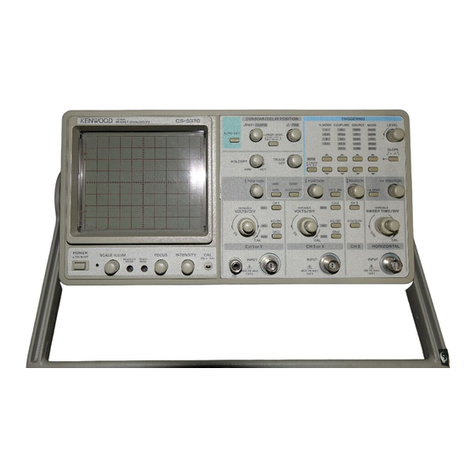
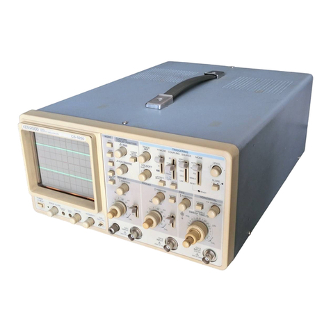
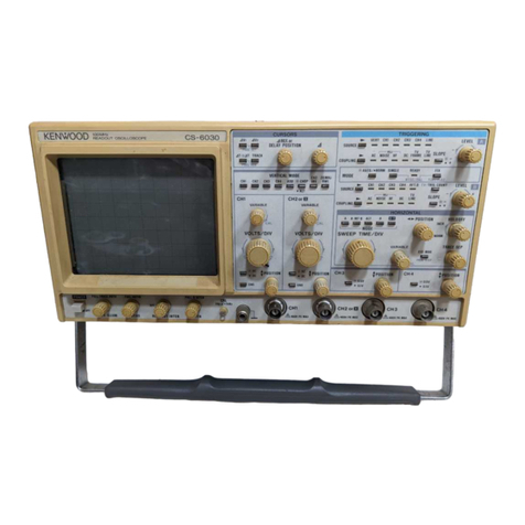
Kenwood CS-5140 User manual

40MHzDUAL
TRACE
OSCILLOSCOPE
CS-5140
INSTRUCTION
MANUAL
KENWOOD
CORPORATION
©PRINTED
IN
JAPAN
B50-7622-20(M)(T)
91/12111098765432190/12111098765432
KENWOOD

SAFETY
SymbolinThis
Manual
AThissymbolindicateswhereapplicablecautionaryor
ZIX
other
imformation
istobe
found.
PowerSource
This
equipment
operates
from
a
power
source
that
does
not
apply
more
than
250V rmsbetweenthesupplycon-
ductors
orbetween
either
supply
conductor
and
ground.
A
protective
ground
connection
bywayofthe
grounding
con-
ductor
inthe
power
cord
isessentialforsafe
operation.
GroundingtheProduct
This
equipment
is
grounded
through
the
grounding
conduc-
torofthe
power
cord.Toavoidelectricalshock,
plug
the
power
cord
into
a
properly
wired
receptacle
before
connec-
ting
tothe
equipment
input
or
output
terminals.
Use
theProperPowerCord
Use
only
the
power
cord
and
connector
specifiedfor
your
product.
Use
theProperFuse
To
avoid
fire
hazard,usea fuseofthecorrecttype.
DonotOperateinExplosiveAtmospheres
To
avoidexplosion,donot
operate
this
product
inanex-
plosiveatmosphere.
DonotRemoveCoverorPanel
To
avoidpersonal
injury,
donotremovethecoverorpanel.
Refer
servicingto
qualified
personnel.
Voltage
Conversion
Ifthe
power
sourceisnot
applied
to
your
product,
contact
your
dealer.Toavoidelectricalshock,donot
perform
the
voltage
conversion.
CONTENTS
SAFETY
2
FEATURES...
3
SPECIFICATIONS
4
PRECAUTIONS..
. 7
CONTROLS
ANDINDICATORS8
FRONTPANEL8
REAR
PANEL12
DIRECTIONSFORUSE..13
OPERATION14
[A]OPERATIONASA
GENERAL-USE
OSCILLOSCOPE..14
[
1
] NORMAL
SWEEP
DISPLAYOPERATION14
[2]SWEEPMAGNIFICATIONOPERATION16
[3]X-YOPERATION16
[4]VIDEOSIGNALOBSERVATION16
[B]EQUIVALENTSAMPLING16
[C]READOUTOPERATION17
APPLICATION18
PROBE
COMPENSATION18
TRACE
ROTATIONCOMPENSATION18
1.
DCVOLTAGEMEASUREMENTS18
2.MEASUREMENTSOFTHEVOLTAGE
BETWEEN
TWOPOINTSONA WAVEFORM19
3.
ELIMINATION
OFUNDESIREDSIGNAL
COMPONENTS....20
4.VOLTAGERATIOMEASUREMENT
USINGCURSORS.20
5.
TIME
MEASUREMENTS21
6.
TIME
DIFFERENCE
MEASUREMENT21
7.
PULSE
WIDTH
MEASUREMENTS.22
8.
PULSE
RISE
TIME
ANDFALLTIME~
MEASUREMENTS23
9.PHASE
DIFFERENCE
MEASUREMENTS24
10.
TIME
RATIOMEASUREMENTUSINGCURSORS.25
11.
FREQUENCYMEASUREMENTS26
12.RELATIVEMEASUREMENTS.27
13.APPLICATIONOFX-YOPERATION...28
14.APPLICATIONASANEQUIVALENT-SAMPLING
OSCILLOSCOPE
29
MAINTENANCE31
RESETTING
THEREADOUTCALENDERAND
CLOCK
DISPLAY
32
ACCESSORIES
33
2

FEATURES
The
CS-5140
isanoscilloscopeincorporating40MHz
real-timeoscilloscopefunctionsanda samplingfunction
forthebandwidthof100MHz(withautomaticsweep
rangeswitching).InformationdisplayedontheCRTin-
cludes:
calendar,vertical
axis
input
sensitivityandsweep
timeduetoreadoutfunction,timedifferenceandvoltage
differencebetweentwocursorlinesduetocursorfunction.
These
featuresallowphotographingforeasiercollectionof
data.
1.
Vertical
axis
hashighsensitivityandwidebandwidth
andespeciallycoversfullyspecifiedfrequencyresponse
at5 mV/div.
REAL
TIME:
40MHz(-3dB)[1mV,2 mV:5MHz
(-3
dB)]
EQUVALENT
SAMPLING:
100MHz(-3dB)[1mV,
2
mV:5MHz(-3dB)]
2.
Holdoff
controlpermits
triggering
ofsignalsofintricate
timerelations.
3.
Triggercoupling
(HFrej)
assures
triggering
ofsignals
containinghigh-frequencynoise.
4.
Verticalsensitivityrangeisselectable
from
1 mV/divto
5
V/div
with
rotaryswitchcontinuously.
5.
Timebasepermitshighsweepspeed.
1
nsec/div(x10MAG)(atsampling)
6.
150mmrectangular,domed-mesh,typeCRT
with
in-
ternalgraticuleandafteracceleration(accelerating
voltage12kV)ensureseasy-to-see,parallax-free
waveformobservations.
7.
Forconvenienceinmakingrisetimemeasurements,the
0%,
10%,90%and100%levelsaremarkedonthe
graticule
scale
oftheCRT.
8.
Trace
rotation
iselectricallyadjustable
from
the
front
panel.
9.
By
SCALE
ILLUMcontrol,thewaveformis
easy
observed
inthedarkandthephotographofthe
waveformis
easy
provided.
10.
SelectableAUTO
FREE
RUNfunctionprovidessweep
without
trigger
input
signal.
11.
The
FRAME-LINE
switchprovidesselectionof
sync
pulse
forsweep
triggering
from
smallamplitudeto
largeamplitude
without
adjustingwhenviewingcom-
positevideowaveforms.
12.
X-Yoperationiseasilyprovidedbyone-touche
button
operation.
CH1
Y
axis,
CH2
X
axis
13.
Therealmodeorsamplingmodeisautomatically
selected
accordingtothesweeprange,eliminating
troublesomeoperation.
14
Thereadoutfunctiondisplayseach
scale
factoronthe
CRT,
eliminatingtroublesomeconfirmationofthe
rangeforwaveformobservation.
WhentheprovidedprobePC31is
used,
thevertical
sensitivitydisplayontheCRTwillbemagnifiedby10
times.
15
Thecursormeasurementmodedisplays,inletters,
voltagedifference,voltageratio,timedifference,time
ratio,frequency,andphasedifferencecorresponding
tothecursormovement.
This
displayeliminates
calculationhavingbeenmadebyanoperator,resulting
inaccuratewaveformobservation.
3

SPECIFICATIONS
CRT
150
mmrectangular
with
internalgraticule
AccelerationVoltage
12
kV
Display
Area
8x10
div(1div= 10mm)
VERTICAL
AXIS
(CH1andCH2)
Sensitivity
1
mV/divto5 V/div,±3%
Attenuator
12
steps,1 mV/divto5 V/divin
1
-2-5sequence.
Vernier
control
for
fully
adjustablesensitivitybetweensteps.
Input
Impedance
1
MO±2%approx.24pF
Frequency
Response
DC
REAL
TIME:
DCto40MHz,-3dB(5mVto5 V/div)
DC
to5 MHz,-3dB(1mV,2 mV/div)
EQUIVALENT
SAMPLING:
DCto100MHz,-3dB(5mVto5 V/div)
DC
to5 MHz,-3dB(1mV,2 mV/div)
Frequency
Response
AC
REAL
TIME:
5 Hzto40MHz,-3dB(5mVto5 V/div)
5
Hzto5 MHz,-3dB(1mV,2 mV/div)
EQUIVALENT
SAMPLING:
5 Hzto100MHz,-3dB(5mVto5 V/div)
5
Hzto5 MHz,-3dB(1mV,2 mV/div)
Rise
Time
REAL
TIME:
8.8
nsec
or
less
(40MHz,-3dB)
70
nsec
or
less
(5MHz,-3dB)
EQUAL
SAMPLING:
3.5
nsec
(100MHz,-3dB)
70
nsec
(5MHz,-3dB)
Crosstalk
—
40dBminimum
OperatingModes
CH1
singletrace
OperatingModes
CH2
singletrace
OperatingModes
ALT
Two-waveformsdisplayalternting
OperatingModes
CHOP
do
OperatingModes
ADD
CH1
+ CH2addeddisplay
ChopFrequency Approx.250kHz
fi\ Maximum
Input
voltage
500
Vp-por250V (DC+ ACpeak)
HORIZONTALAXIS
Input
thru
CH2,x 10MAGnotincluded
OperatingModes
With
TRIG
MODEswitch,X-Yoperationisselectable
(REAL
TIME)
CH1
; Y
axis
CH2
; X
axis
Sensitivity
Same
asvertical
axis
(CH2)
Input
Impedance
Same
asvertical
axis
(CH2)
Frequency
Response
DC DC
to500kHz,-3dB
Frequency
Response
AC
5
Hzto500kHz,-3dB
X-Y
Phase
Difference 3°or
less
at50kHz
/t\Maximum
Input
Voltage
Same
asvertical
axis
(CH2)
SWEEP
Sweep
System
NORM Triggeringsweep
Sweep
System
AUTO
Sweep
freerunsinabsenceof
trigger
Sweep
Time 0.2s/divto10ns/div,±3%,in23ranges,in1-2-5sequence.
Vernier
control
provides
fully
adjustablesweep
time
betweensteps.
REAL
TIME:
0.2s-0.2/xs/div
EQUIVALENT
SAMPLING:
0.1/i~10ns/div
4

Sweep
Magnification
x
10(tentimes)±5%
Linearity
±3%
(x10MAG,0.2/iS~10jis,±5%)
HOLD
OFF Adjustablebythecontroller
TRIGGERING
Internal
Sync
CH1
TriggeredbyCH1signal
CH2
TriggeredbyCH2signal
LINE
Triggeredbylinefrequency
External
Sync
EXT
TriggeredbysignalappliedtoEXT
TRIG
INPUT
jack
External
Sync
InputImpedance Approx.1 MG,approx.32pF
ft\
Max.
ExternalTriggerVoltage
50
V (DC+ ACpeak)
Coupling
AC,
HFrej,
TV
FRAME,
TV
LINE
Sync
sensitivity AtNORMposition
AC
Sync
frequencyrange: 10Hz- 50MHz
INT
: 1 div,EXT: 0.1Vp-p
Sync
frequencyrage: 10Hz~ 100MHz
INT
: 1.5div,EXT: 0.2Vp-p
HFrej
The
sync
frequencyrangeismorethan10kHz,andtheminumumamplitude
(Voltage)
requiredfor
sync
isincreased.
TV
FRAME,
LINE
INT
: 1.5div,EXT: 0.15Vp-p
(AUTO)
Rating
shownaboveisprovidedat50Hzorover.
CALIBRATION
VOLTAGE
1
V ±3%,squarewave,positivepolarity,approx.1 kHz
INTENSITY
MODULATION
Sensitivity
+
5 V,positivevoltagedecreasesbrightness.
InputImpedance Approx.10kO
Usable
FrequencyRange
DC
to2 MHz
A
MaximumInputVoltage
50
V (DC+ ACpeak)
READOUT
Calendar
Year/Month/Day/O'clock/Minute
Clock
accuracy: ±2
min./month
Battery
life: About20,000hours(atroomtemperature)
Set
value
CH1/CH2
scale
factor(withprobedetection);
V-UNCAL,
ADD,
INVERT
Sweep
scale
fator(magnificationconversion);
SWEEP
VARIABLE-UNCAL,
X-Y
Cursor
mode:
4V1:
Voltagedifferencebetween
AREF
andA cursorsonthe
basis
ofCH1
scale
factor
AV2: Voltagedifferencebetween
AREF
andA cursorsonthe
basis
ofCH2
scale
factor
AT:
Time
differencebetween
AREF
andA cursorsonthe
basis
ofsweep
scale
factor
MAI:
Frequency
between
AREF
andA cursorsonthe
basis
ofsweep
scale
factor
Ratio:
Voltageratioandtimeratiobetween
AREF
andA cursors,supposing
5
div.onthe
CRT
as100%
Phase:
Phase
differencebetween
AREF
andA cursors,supposing5 div.onthe
CRT
as360°
NOTE:
TheX-YmodeallowsAS/I measurementonly.
Cursor
Resolution
10
bits
measurement Measurement
accuracy
±4%
Measurable
range AV, Ratio:±3.6divormore
from
theCRTcenter
AT, VAT, Ratio,
Phase:
±4.6divormore
from
theCRTcenter
5

TRACE
ROTATION(Electrical,adjustable
from
front
panel)
POWER
REQUIREMENT
Line
Voltage
100
V/120V/220V/240VAC+10%
Line
Frequency
50/60
Hz
Power
Consumption Approx.53W
DIMENSIONS
(WxHxD)
319
(341)x132(145)x380(442)mm
(
) dimensionsincludeprotrusion
from
basic
outline
dimensions
WEIGHT Approx.9.5kg
ENVIRONMENTAL
Within
Specifications 10°Cto35°C,85%max.relative
humidity
Full
Operation 0°Cto40°C,85%max.relative
humidity
ACCESSORIES
SUPPLIED
Probe
PC-31
(READOUT
compatibleprobe)x 2
Attenuation...1/10
Input
impedance...10MQ+
1%,
14pF+10%
Power
supplycable
1
Replacement
Fuse
1.2AX2,
0.8AX2
InstructionManual
1
*Circuitandratingaresubjecttochange
without
noticeduetodevelopmentsintechnology.
6

PRECAUTIONS
Plug
configuration
Power
cordandplugtype
Factory
installed
instrumentfuse
Line
cordplugfuse
North
American
120volt/60Hz
Rated
15amp
(12ampmax;NEC)
1.2A,250V
Fast
blow
6
x
30mm None
Universal
Europe
220volt/50Hz
Rated
16amp
0.8A,250V
T.
lag
5x20mm None
U.K.
240volt/50Hz
Rated
13amp
0.8A,250V
Fast
blow
6x30mm
0.8A
Type
C
Australian
240volt/50Hz
Rated
10amp
0.8A,250V
Fast
blow
6
x
30mm None
North
American
240volt/60Hz
Rated
1
5 amp
(12ampmax;NEC)
0.8A,250V
Fast
blow
6
x
30mm None
Switzerland
240volt/50Hz
Rated
10amp
0.8A,250V
Fast
blow
6x 30mm None
Fig.
1 PowerInputVoltageConfiguration
1.
Check
thepowersupplyvoltagebeforeuse.A voltage
selector/fuse
holderisprovidedonthe
left
sideoftheAC
inletsocket,ontherearpaneloftheset.Thelinevol-
tagesettingisindicatedbya trianglemarkabovethefuse
holder.Ifthevoltageisdifferent
from
thepowersupply
inyour
area,
setitcorrectlytopreventdangerand
mal-
functions.
Besuretocheckthevoltagebeforeconnect-
ingthepowerplugtoanAC
outlet.
•
Whenconvertingthevoltage,refertotheMaintenance
section.
2.
The
CS-5140
shouldbeinstalledata placemeetingthe
following
conditions:
1
Directsunlight
2
Hightemperatureandhumidity.
3
Frequetmechanicalvibration.
4
Strongmagnetic
rays
orimpulsevoltagepossibly
generated
from
equipmentlocatednearby.
3.
Neverapplymorethanthemaximumratedvoltagetothe
oscilloscope
input
jacks.
A
CH1,CH2
input
jacks:
500
Vp-por250V
(DC
+ AC
peak)
EXT
TRIG,
Z
AXIS
input
jacks:
50
V
(DC
+ AC
peak)
Never
applyexternalvoltagetotheoscilloscope
output
terminals.
4.
Donot
increase
theintensitymorethanrequired.
5.
Neverallowa smallspotofhighbrilliancetoremainon
the
screen
forextendedperiodsoftime.
6.
Nevercovertheventilatingholesinthetopofthe
scope,
asthiswill
increase
thetemperatureinsidethe
case
therebycausingmalfunction.
7.
Whenremovingthe
case,
observethemaintenancein-
structioncontainedinthismanualtopreventa safety
hazard
because
thisinstrumentcontainshighvoltage
circuits.
8.
Toprotectagainstsafety
hazards
always
groundthe
instrumentusingtheGNDterminalsonthepanel.
9.
When
turning
onandoffthe
POWER
switchrepeated-
ly,
keepanintervalofabout5
seconds.
Faster
onand
offoperationmay
cause
malfunctiontotheinstru-
ment.
10.
DonotusetheprovidedPC-31Probe
with
other
measuring
equipment
because
itincorporatesa ter-
minalfor
READOUT
detectionwhich
might
damage
theotherequipment.
11.
Forproperuseofthecalendarandclockdisplay,be
sure
toadjustthedateandtimecorrectly.
(Refer
tothe
"Maintenance
andAdjustment"section.)
12.
Thecalendarandclockdisplayarebackedupbyanin-
corporatedbattery.Ifthebatteryisnearlyexhausted,
thedateandtimewillbedelayed.Ifthishappens,the
incorporatedbatterymustbereplaced
with
a newone.
Please
contactyourdealerorKenwood
service
agent
for
assistance.
7

CONTROLS
ANDINDICATORS
FRONT
PANEL
©CH1$ POSITION
Rotationadjustsvertical
position
ofCH1waveformon
thescreen.InX-Yoperation,this
control
adjustsY
axis
position.
(DcmVOLTS/DIV
Verticalattenuatorforchannel1.Providesstepadjust-
mentofverticalsensitivityin1-2-5sequence.
VARI-
ABLE
(3)
control
isturnedtotheCALposition,the
calibratedverticalsensitivityisobtained.InX-Yopera-
tion,this
control
serves
astheattenuatorforY
axis.
(DCH1VARIABLEControl
Rotationprovidesfine
control
ofchannel1 vertical
sensitivity.Inthe
fully
clockwise(CAL)position,the
verticalattenuatoriscalibrated.InX-Yoperation,this
control
serves
astheY
axis
attenuationfineadjust-
ment.
(4)
CH1AC-GND-DC
This
switchistheCH1vertical
axis
couplingmode
selector,forX-Yoperation,the
Y-axis
couplingmode
control.
AC:
AC
input
coupling
with
blockingofanyDC
signalcomponent.
GND:
Verticalamplifierisdisconnected
from
thein-
putsignalandconnectedtoground.Thismode
is
usefulindeterminingthezeroreference.
DC:
DCcoupling,
with
both
theDCandACcom-
ponentsofthe
input
signaldisplayedonthe
CRT.
(DCH1INPUT
Jack
Vertical
input
forchannel1 traceinnormalsweep
operation.Vertical
input
forX-Yoperation.
(6)
CH2VOLTS/DIV
VerticalattenuatorforCH2.Providesthesamefunc-
tion
as
VOLTS/DIV
Control(2)for
CH1.
InX-Yopera-
tion,the
control
serves
asthe
X-axis
attenuator.
(J)
CH2VARIABLEControl
Rotationprovidesfine
control
ofchannel2 vertical
sensitivity.
Provides
thesame
function
as
VARIABLE
Control(§)
for
CH1.
InX-Yoperation,this
control
serves
for
X-axis
at-
tenuationfineadjustment.
(8)
CH1AC-GND-DC
Selects
thecouplingofchannel2 vertical
input
signal.
InX-Yoperation,theswitchprovides
input
selectionof
X-axis
andperformsthesame
function
asAC-GND-DC
©forCH1.
(9)
CH1INPUT
Jack
Vertical
input
forchannel2 traceinnormalsweep
operation.Externalhorizontal
input
inX-Yoperation.
(fj))
CH2$ CH2POSITION,
PULL
INV
T
CH2
POSITION:
Rotationadjustsvertical
position
of
channel2 trace.
INV:Push-pullswitchselectschannel2
signalinverted
(PULL
INV)when
pulledout.
(Hereafter
PULL
INVisdescribedas
CH2
INV.)
8
Fig.
2

(Q)
MODE
Selects
thebasicoperatingmodesoftheoscilloscope.
CH1:
Onlythe
input
signaltochannel1 is
displayedasa singletrace.
CH2:
Onlythe
input
signaltochannel2 is
displayedasa singletrace.
ALT:
Alternatesweepisselectedregardless
ofsweeptime.
CHOP:
Chopsweepisselectedregardlessof
sweep
time
atapproximately250kHz.
ADD:
Thewaveforms
from
channel1 and
channel2 inputsareaddedandthesum
is
displayedasa singletrace.Whenthe
CH2
INV@
button
isengaged,the
waveform
from
channel2 issubtracted
from
thechannel1 waveformandthe
differenceisdisplayedasa singletrace.
@
POWER
Power
switch.A pressofthisswitchturnsthepower
ON.
(JDPOWERLED
Lightswhenoscilloscopeisturnedon.
(g)_QGNDterminal/bindingpost.
Earth
and
chassis
ground.
(15)CAL
Provides
approximately1 kHz,1 V peak-to-peak
square
wavesignal.Thisisusefulforprobecompensa-
tion
adjustment.
@
INTENSITY
(REAL)
Adjuststheintensityoftrace.
@
READOUTINTENSITY
Adjuststheintensityofthecharactersinthe
READ
OUT
lineandthecursor.Fullcounterclockwiserota-
tion
turnsoffthe
READOUT
function.
FOCUS/PULL
ASTIG
FOCUS:
Adjuststhetracefor
optimum
focus.
ASTIG:
Usedto
bring
thewaveform
into
thebest
condition
with
the
FOCUS
adjustmentby
adjustingtraceandspotaberration.Pullthe
knobtomakea spotcircular.
(§)
SCALE
ILLUM/PULL
TRACE
ROTA
SCALE
ILLUM:
Brightnessadjustmentofthe
scale
oftheCRT.Forphotographing,
rotate
theknobtoadjustbrightness
topreventhalationcausedbytoo
bright
illumination.
TRACE
ROTA:
Usea screwdrivertoadjustthe
tracetoa horizontalposition.Once
adjusted,this
control
doesnotre-
quirefrequentreadjustment.
(§)EXTTRIGINPUT
Jack
Input
terminalforexternal
trigger
signal.
When
SOURCE
switchisselectedinEXTposition,the
input
signalattheEXT
TRIG
INPUTjackbecomesthe
trigger.
@
LEVEL/PULL
SLOPE
{-)
LEVEL:
Triggerleveladjustmentdeter-
mines
point
onwaveformwhere
sweep
starts.
When
COUPLING
switchis
selected
in
VIDEO-FRAME
or
LINE,
the
trigger
leveladjustmenthasno
effect.
PULL
SLOPE
(-): Two-positionpush-pullswitch.
Switch
Pulledout
position
selectsnegative
going
(—)slopeandpushedinposi-
tion
selectspositive-going(+)
slopeas
triggering
point.
(§)COUPLING
Selects
couplingforACsync
trigger
signal.
AC:
Triggerisaccoupled.BlocksDCcomponent
of
input
signal;mostcommonlyusedposi-
tion.
HFrej:
Sync
signaliscoupled
through
a low-pass
filter
toeliminate
high
frequencycomponents
forstable
triggering
oflowfrequencysignals.
TV
: Verticalsyncpulsesofa compositevideo
FRAME
signalareselectedfortriggering.
TV
: Horizontalsyncpulsesofa compositevideo
LINE
signalareselectedfortriggering.
(§)
SOURCE
CH1:
Channel1 signalisusedasa
trigger
source.
CH2:
Channel2 signalisusedasa
trigger
source.
LINE:
Sweepis
triggered
bylinevoltage
(50/60
Hz).
NOTE:
Whenthe
COUPLING
switchissettoother
thanACsynchronizationmaynotbeobtain-
ed.
Inthis
case,
setthe
COUPLING
switchtothe
AC
position.
EXT:
Sweepis
triggered
bysignalappliedtoEXT
TRIG
INPUTjack(§).
(g)TRIGGERINGMODE(TRIGMODE)
Selects
triggering
mode.
AUTO:
Triggeredsweepoperationwhen
trigger
signalispresent,automaticallygenerates
sweep
(freeruns)inabsenceof
trigger
signal.
NORM:
Normal
triggered
sweepoperation.Notraceis
presentedwhena proper
trigger
signalisnot
applied.
X-Y:
X-Yoperation.Channel1
input
signalpro-
duces
verticaldeflection(Y
axis).
Channel2
input
signalproduceshorizontaldeflection(X
axis).
This
operatesregardlessverticalMODE
selec-
tion.
9

(§)
SWEEP
VARIABLE
Control
This
isthesweepratefine-adjustmentcontrol,which
allows
continuousvariationbetween
SWEEP
TIME/DIV
ranges.
The
sweepratecanbecalibratedwhenthecontrolis
turnedfullyclockwisetotheCALposition.
(§)
SWEEP
TIME/DIV
Horizontalcoarsesweeptimeselector.
Selects
calibratedsweeptimesof0.2^.s/divto
10
ns/divin23stepswhensweeptime
VARIABLE
control@)issettoCALposition(fullyclockwise).
Measurementintherangebetween0.1/ts/divand
10
ns/divisautomaticallyperformedintheequivalent
samplingmode,allowingobservationsofrepetitive
waveforms.
Atthesametime,thebandwidthisex-
tendedto100MHzprovidedthatthevertical
axis
at-
tenuatorisintherangebetween5 mV/divand
5
V/div.
@
POSITION/PULLx 10MAG
Horizontalpositioncontroller,whichprovideshorizon-
talshiftofwaveform.By
pulling
theknob,thesweep
timeisquickenedtentimes.
IntheX-Yoperationmode.ItfunctionsasanX posi-
tion
controller.AlsofunctionsasanX positioncon-
trollerofthestoragewaveform.
NOTE:
InX-Yoperation,keepthisknobpressed
(normalsweepmode).
(§)HOLDOFF
Adjusts
thesweep-to-sweepinterval.Turningthe
HOLDOFF
from
theNORM(fullc.c.w.)positionvaries
the
holdoff
timetomorethanx 10attheMAX(full
c.w.)
position.
(§) A
Controllerforshiftingthemeasuringcursor(rough
dot-
tedline)outoftwocursorlinesdisplayedonthe
CRT
in
thecursormeasurement.By
rotating
thecontroller
clockwise,
thecursorlinemovesupwardorrightward:
by
rotating
counterclockwise,itmovesdownwardor
leftward.
(§) A REF
Controllerforshiftingthereferencecursor(small-
dotted
line)outoftwocursorlinesdisplayedonthe
CRT
inthecursormeasurement.By
rotating
thecon-
trollerclockwise,thecursorlinemovesupwardor
rightward:by
rotating
counterclockwise,itmoves
downwardorleftward.
(§)
CURSORS
Cursor
measurementmodeselectswitch.
OFF:
Cursormeasurementisnotperformed.Thecur-
sor,
andcursourmeasurementmodeandcur-
sor
measurementvaluearenotdisplayedon
the
CRT.
AMI:
Twohorizontalcursorlinesaredisplayedonthe
CRT,
andvoltagedifferenceandvoltageratio
betweenthemaredisplayedintheupper
right
ontheCRTposteriortothecursormeasure-
mentmodedisplay.
SettingtheCH1
VARIABLE
controller(§)to
theCALposition
causes
voltagedifference
measurement,
anda valuecalculatedinaccor-
dance
with
settingoftheCH1
VOLTS/DIV
dial
(2)
isdisplayedposteriorto<4V1.
SettingtheCH1
VARIABLE
controller(§)tothe
UNCAL
position
causes
voltageratiomeasure-
ment,anda valuecalculatedassumingthat5 div.
is
100%isdisplayedposteriortothe
RATIO.
WhentheA cursorisbelowtheA REF
cursor,
a negativevalueisdisplayed.
NOTE:
SettingoftheMODEselectswitch(Q)to
theCH2position
causes
A V2mode
cursor
measurement.
10
Fig.
3

AV2: Twohorizontalcursorlinesaredisplayedonthe
CRT,
andvoltagedifferenceandvoltageratio
betweenthemaredisplayedintheupper
right
ontheCRTposteriortothecursormeasure-
mentmodedisplay.
SettingtheCH2
VARIABLE
controller(7)to
theCALposition
causes
voltagedifference
measurement,
anda valuecalculatedinaccor-
dance
with
settingoftheCH1
VOLTS/DIV
dial
(Disdisplayedposteriorto^1V2.
SettingtheCH2
VARIABLE
controller(f) to
theUNCALposition
causes
voltageratio
measurement,
anda valuecalculatedonthe
basis
of5 div.as100%isdisplayedposterior
tothe
RATIO.
WhentheA cursorisbelowthe
^IREF
cursor,
a minusvalueisdisplayed.
NOTE:
SettingoftheMODEselectswitch(Tj)
totheCH1position
causes
AVI
modecursormeasurement.
SettingoftheMODEselectswitch%
totheX-YpositiondisablesAV2
modemeasurement.
AT:
Twoverticalcursorlinesaredisplayedonthe
CRT,
andtimedifferenceandtimeratiobet-
ween
themaredisplayedintheupper
right
on
theCRTposteriortothecursormeasurement
modedisplay.
Settingthe
SWEEP
VARIABLE
controller(§)to
theCALposition
causes
timedifference
measurement,
anda valuecalculatedinaccor-
dance
with
settingofthe
SWEEP
TIME/DIV
dial
@)
isdisplayedposteriortoAT.
Settingthe
SWEEP
VARIABLE
controller@ to
theUNCALposition
causes
timeratiomeasure-
ment,anda valuecalculatedassumingthat
5
div.is100%isdisplayedposteriortothe
RATIO.
WhentheA cursorisonthe
left
oftheA
REF
cursor,a minusvalueisdisplayed.
NOTE:
SettingoftheMODEselectswitch@)
totheX-YpositiondisablesAT
modemeasurement.
1/AT:
Twoverticalcursorlinesaredisplayedonthe
CRT,
andfrequencyandphasedifferencebet-
ween
themaredisplayedintheupper
right
on
theCRTposteriortothecursormeasurement
modedisplay.
Settingthe
SWEEP
VARIABLE
controller(§)to
theCALposition
causes
frequencymeasure-
ment,anda valuecalculatedinaccordance
with
settingofthe
SWEEP
TIME/DIV
dial@ is
displayedposteriortoMAT.
Settingthe
SWEEP
VARIABLE
controller(§)to
theUNCALposition
causes
phasedifference
measurement,
anda valuecalculatedassuming
that5 div.is360°isdisplayedposteriortothe
PHASE.
WhentheA cursorisonthe
left
oftheA
REF
cursor,a minusvalueisdisplayed.However,
frequencyisdisplayedinanabsolutevalue.
NOTE:
SettingoftheMODEselectswitchto
theX-YpositiondisablesMAT mode
measurement.
11

REAR
PANEL
(§)Z AXISINPUT
External
intensitymodulation
input;
TTLcompatible.
Positive
voltage
increases
brightness,negativevoltage
decreases
brightness.
(§)
Fuse
Holder,
Line
VoltageSelector
Contains
theline
fuse.
Verifythattheproperfuseisin-
stalled
whenreplacingtheline
fuse.
100
V,120V .............................................1.2A
220
V,240V 0.8A
After
pulling
thepowercordplug
from
thepower
outlet,
adjustthisselectortoyourlinevoltage.
(fl)PowerInputConnector
Inputterminalsofpowersupply.ConnecttheACcord
provided.
12
Fig.
4

DIRECTIONS
FORUSE
READOUT
DISPLAY
CD
POSITIONS
OFTHE
DISPLAY
Displays
thecalendar,
scale
factors,cursor
measurementdata,etc.atthe
following
positionsontheCRT.
Fig.
5
12)
DISPLAYCONTENTS
1
Calendar/Clock
Displays
a calendarandclockinthe
following
order:
Month-Day-Year-O'clock-Minute
Month:
JAN,
FEB,
MAR,APR,MAY,JUN,JUL,
AUG,
SEP,
OCT,NOV,DEC
Day:
01to31
Year:
00to99
O'clock:00to23
Minute:00to59
These
settingcanbechanged
with
theswitchlocated
onthe
bottom.
(Forresetting,refertotheMaintenance
section.)
2
Cursor
Mode
The
currentsettingcursormode,whichdependsonthe
combinationoftheoperationcontrols,isdisplayed.
AV2, AT, MAT,
RATIO,
PHASE
3
CursorMeasuringData
The
resultmeasuredbythetwocursorsisdisplayed.In
the1MTmode,whenthetwocursorsapproach
each
otherandthemeasurementnearsits
limit,
a "?"
will
bedisplayedin
front
ofthemeasureddata.This
shows
that
themeasureddataisnotavailable.
4CH1
Scale
Factor
Displays
theCH1vertical
axis
sensitivitytoonedivi-
sion.
WhennotinCALmode,a ">"isdisplayedafter
CH1.
NOTE:
ThisisnotdisplayedwhentheMODE
control
(Q)issettoCH2.
5
CH2
Scale
Factor
Displays
theCH2vertical
axis
sensitivitytoonedivi-
sion.
WhennotinCALmode,a ">"isdisplayedafter
CH2.
NOTE:
ThisisnotdisplayedwhentheMODE
control
©issetto
CH1.
6ADD
"+ " isdisplayedwhentheMODE
control
(Jj)issetto
ADD.
7CH2INVERT
The
inverted
polarity
ofCH2
"J"
isdisplayedbycon-
trolling
the•
POSITION/PULL
INV(jjj).
8Sweep
Scale
Factor
Displays
thesweeprangesetbythe
SWEEP
TIME/DIV.
Whenthe
SWEEP
VARIABLE
isnotinCALmode,a ">"
is
displayed.When
TRIGGERING
MODEissettoX-Y,
thisdisplayischangedto
"X-Y".
13

OPERATION
INITIALSTARTING
PROCED
Priorto
turning
thepowerON,settheswitchesasinthe
drawingbelowinadvance.Fordetailsofswitchsetting,
refertothe
item
"Front
Panel".
Inthe
case
ofusinga pro-
be,
refertotheOperationManualattachedtotheprobeas
wellastheapplicationexample"ProbeCompensation".
Fig.
6
[A]OPERATIONASA
GENERAL-USE
OSCILLO-
SCOPE
[1]Normalsweepdisplayoperation
1.
Press
the
POWER
switch@ tosupplypower,andthe
POWER
LED@>lights.
2.
A
bright
lineappearsintheCRTcenter.Ifitisnotinthe
center,adjustits
position
tothecenter
with
the•
POSI-
TION
controller(T).
Then,
adjustthebrightness
with
the
INTENSITY
controller(fj), andthefocus,
with
the
FOCUS
controller(f|)asrequiredfor
easy
observation.
3.
Supply
input
signal
into
theCH1
INPUT
jack®.Rotate
the
VOLTS/DIV
dial(2)toadjustwaveformtoap-
propriatedimensions.
Set
theMODEselectswitch(Q)toCH2,andthe
TRIG-
GERING
SOURCE
selectswitch(§)toCH2.
Then,
sup-
ply
input
signal
into
theCH2
INPUT
connector(9).Its
waveformisdisplayedontheCRTinthesamepro-
cedures
with
channel1.
WhentheMODEselectswitchissettoADD,thecom-
positewaveformsofCH1andCH2(thealgebraicsum-
ofCH1+ CH2)isdisplayedonthe
CRT.
Inthisstatus,if
CH2
INVisengagedby
pulling
outtheCH2T
POSI-
TION,
thealgebraicdifferencebetweenCH1andCH2
(CH1
-CH2)
will
bedisplayed.
The
sensitivityoftheADDedwaveformbecomesthe
same
asthevalueindicatedby
VOLTS/DIV
provided
that
tnesame
VOLTS/DIV
valuehasbeensetforthe
waveformsofthetwochannels.
WhentheMODEselectswitch(fj)issettoALT,the
channel-1andchannel-2waveformsaredisplayedalter-
natelyineverysweep.Inthis
case,
the
SOURCE
select
switch@)shouldbesettothechanneltobe
syn-
chronized.
4.
Thedisplayonthescreen
will
probablybeunsynchroniz-
ed.
Refer
to
TRIGGERING
procedurebelowforadjusting
synchronizationandsweepspeedto
obtain
a stable
displayshowingthedesirednumberofwaveform.
TRIGGERING
The
input
signalmustbeproperly
triggered
forstable
waveformobservation.
TRIGGERING
ispossiblethein-
putsignalINTernallytocreatea
trigger
or
with
anEX-
Ternally
providedsignalof
timing
relationshiptothe
observedsignal,appliyingsucha signaltotheEXT.
TRIG
INPUT
jack@>.
(1)
Theselectionofa signal
that
serves
asthe
trigger
signalismadeusingthe
SOURCE
switch@).
*Internal
Sync
Whenthe
SOURCE
selectionisinINT(CH1,CH2,
LINE),
the
input
signalisconnectedtotheinternal
trigger
circuit.Inthisposition,a partofthe
input
signalfedtothe
INPUT
(5)or(9)jackisapplied
from
theverticalamplifiertothe
trigger
circuitto
cause
the
trigger
signal
triggered
with
the
input
signaltodrivethesweep.
With
the
SOURCE
selectorsettoCH1orCH2,a
trigger
isdeveloppedbytheCH1orCH2signal
regardless
oftheMODEsetting.
Settingthe
SOURCE
selectswitch@)to
LINE
causes
synchronization
with
commercialpowerfre-
quency.
14
Rotatecounterclockwise
uptotheveryend•
Threeo'clockposition
Center
Push'
Rotatecounterclockwise
uptotheveryend
•
Center
Push
•Center
Push

•
External
Sync
Whenthe
SOURCE
selectionisinEXT,the
input
signalat
theEXT.
TRIG
INPUT(§)jackbecomesthe
trigger.
This
signalmusthavea
time
orfrequencyrelationshiptothe
signalbeingobservedtosynchronizethedisplay.External
sync
ispreferedforwaveformobservationinmanyapplica-
tions.Forexample,Fig.7 shows
that
thesweepcircuitis
drivenbythegatesignalwhenthegatesignalintheburst
signalisappliedtothe
EXT.TRIG
INPUTjack.
Shows
the
input/output
signals,wheretheburstsignal
generated
from
thesignalisappliedtotheinstrumentunder
test.
Thus,
accurate
triggering
canbeachieved
without
regardtothe
input
signalfedtotheINPUT(5)or(§)jack
so
that
nofurther
triggering
isrequiredevenwhenthe
input
signalisvaried.
EXT.
TRIG
Triggersignal
(Gatesignal)
Fig.
7
Waveform
with
highfrequencynoise
TriggersignalbyHFrejection
Fig.
8
•TriggeringLevel
Trigger
point
onwaveformisadjustedbythe
LEVEL/PULLSLOPE
(fj)control.Showstherela-
tionshipbetweenthe
SLOPE
and
LEVEL
ofthetrig-
ger
point.
Triggeringlevelcanbeadjustedas
necessary.
SLOPE
"-"RANGE
Fig.
9
(2)
Afterthe
SOURCE
hasbeenset,the
trigger
point
can
besetby
rotating
LEVEL/SLOPE
control
@ .
(3)
Selectthecouplingswitch@ .
AC:
The
trigger
signaliscapacitivelycoupled,soitsDC
componentiscut,givinga stable
trigger
whichis
notaffectedbytheDCcomponent.
With
thisad-
vantage,this
position
ofthecouplingswitchiscon-
venientlyselectedforordinaryapplications.
However,ifthe
trigger
signalislowerthan10Hz,
the
trigger
signallevelbecomesattenuated,
resultingin
difficulty
intriggering.
HFRE
J:
The
trigger
signalissupplied
through
a low-pass
filter
toeliminatethehigh-frequencycomponent
(higherthan10kHz),givinga stable
triggering
with
low-frequencycomponent.Whenhigh-frequency
noiseissuperimposedoverthe
trigger
signalas
showninFig.8,thehigh-frequencynoiseiscutto
providea stable
trigger.
•AutoTrigger
Whenthe
TRIG
MODE@)selectionisin
AUTO,
the
sweep
circuitbecomesfree-runningas
long
asthere
is
no
trigger
signal,
permitting
a checkofGNDlevel.
Whena
trigger
signalispresent,the
trigger
point
can
bedeterminedbythe
LEVEL
control
forobser-
vationasinthenormal
trigger
signal.Whenthetrig-
gerlevelexceedsthe
limit,
the
trigger
circuit
becomesfree-runningwherethewaveformstarts
running.
NOTE:
If,
with
the
TRIG
MODEswitchsetto
NORM,
no
trigger
signalis
input
orthetrig-
gersignalexceedsthe
triggering
range,
sweepingisstoppedandtrace
will
notbe
displayed.
•HOLDOFF
In
case
of
triggering
difficulties
that
mayoccur
with
signals
containingdifferentpulsedurations
althoughthepulse
repetition
itselfisconstantas
shownbelow,or
with
complicatedsignalssuchasa
TV
signal,
turn
theHOLDOFF
control
(g)toob-
taina stabletriggering.
15
Inputsignalto
amplifier,etc.
Outputsignal
from
amplifier,etc.
SLOPE
" + " RANGE
LEVEL

5.
Adjustthe
SWEEP
TIME/DIV
control
(§)to
obtain
an
appropriatedisplay.Nowa normalsweepdisplayisob-
tained.
[B]
EQUIVALENTSAMPLING
The
equivalentsamplingmodeisactivatedautomatically
whenthe
SWEEP
TIME/DIV
control
'f|issettotherange
between0.1/xs/divand10/*s/div.Whenthemodeis
swtiched
from
thereal-timemodetoequivalentsampling
mode,thebandwidthisalsoswitched
from
40MHz
(-3dB)to100MHz(-3dB)so
that
thedisplay
amplitudemayvary
with
higher
input
signalfrequencies.
Whenitisrequiredtoobserveamplitudevariations,fixthe
modeeithertothereal-timeorequivalentsamplingmode.
With
a samplingoscilloscope,differentpartsofthe
input
signalaresampled
with
certain
time
differences,andthe
signals
obtrainedareamplifiedandappliedtothevertical
amplifier.Atthesametime,the
time
signalscorresponding
tothesampling
time
differenceareappliedtothehorizontal
amplifier,so
that
thesameimageasthe
input
signalisre-
constructedonthedisplayusingthetwotypesofsignals.
This
systemthereforenecessitates
that
the
input
signalisa
repetitivewaveform,andtherepetitionsshallcontinuefor
a
certainperiodandshallbestable.
[2]
SWEEP
magnificationoperation
Merelyshorteningthesweep
time
tomagnifya
portion
of
observedwaveformcanresultinthedesired
portion
disap-
pearingoffthe
screen,
thedesired
portion
canbedisplayed
without
such
trouble
ifthesweepmagnificationfeatureis
used
(alsoreferto
"Sweep
Magnification"onpage5).
Usingthe< •
POSITION
control,adjustthedesired
por-
tion
ofwaveformtothe
CRT.
Pulloutthe
PULLx
10MAG
control
tomagnifythedisplay10times.Forthistypeof
displaythesweep
time
isthe
SWEEP
TIME/DIV
setting
dividedby10.
[3]X-Yoperation
X-Y
operationpermitstheoscilloscopetoperformmany
measurementsnotpossible
with
conventionalsweep
operation.
Set
the
TRIGGER
MODEswitch(g)totheX-Yposition.In
thismode,channel1 becomestheY
axis
input
andchannel
2
becomestheX
axis
input.
The
X andY positionsarenowadjustedusingthe•
POSITION
@ andCH1•
POSITION
controlsrespectively.
X
andY sensitivityaresetbyusingthechannel2 and
chan-
nel1
VARIABLE
VOLTS/DIV
controlsrespectively.
[41VIDEOsignalobservation
Settingthe
COUPLING
(§)switch,totheTV
FRAME
orTV
LINE
position
permitsselectionofverticalorhorizontal
sync
pulsesforsweep
triggering
whenviewingcomposite
videowaveforms.
This
makesstable
triggering
invideosignalobservations
possibleregardlessofthe
TRIG
LEVEL
control
(£j).
Atmostpointsofmeasurement,a compositevideosignal
is
ofthepolarity,
that
is,the
sync
pulsesarenegativeand
thevideoispositive.Inthis
case,
use" —"
SLOPE.
Ifthewaveformistakenata circuit
point
wherethevideo
waveformisinverted,the
sync
pulsesarepositiveandthe
videoisnegative.Inthis
case,
use" + "
SLOPE.
Fig.
10
Fig.
10showsa
case
inwhicha samplingpulse
that
is
delayedbya specifiedperiod
from
the
input
signalis
generated,andthesignalheldbythesamplingpulse
becomesthe
output
signal.
Intheexampleshowninthisfigure,the
output
signal
SYNC
is
1/12ofthe
input
signal.
NOTE:
Whenthe
input
signalfrequencyislow,thedots
ofthewaveformobservedbyequivalentsampling
become
coarse.
If
triggering
isappliedincorrectly,theequivalent
samplingoperation
will
beabnormal,so
that
the
displayedwaveform
will
be
totally
different
from
thereal
input
signal.
16
CRT
display
Hold-off
time
0Insufficienthold-off
time
(2)Insufficienthold-off
time
(3)
Optimumhold-off
time
Input
Sampling
pulse
Output

[C]
READOUT
OPERATION
1
CRTsurfacereadout
By
rotating
the
INTEN
(READOUT)
controller(g)
clockwise
uptotheveryend,charactersaredisplayed
onthe
CRT.
Adjustthebrightnessasnecessityrequires.
The
CH1andCH2
scale
factorsaredisplayedinthe
lowerpartoftheCRTinaccordance
with
settingofthe
MODE
selectswitch(jj). Thesweep
scale
factoris
displayedinthelower
right
part.By
pulling
the•
POSITION/PULLx
10MAGswitch@ , a
tenth
scale
factorofthe
SWEEP
TIME/DIV
dial@ isdisplayed.The
calendar
isdisplayedintheupperleft.
NOTE:
Ifthe
DATA-ON/OFF
switchonthe
bottom
isset
toOFFposition,thecalendarisnotdisplayed.
For
thecalendarsetting,refertotheitem
"MaintenanceandAdjustment".
Whenthereadoutvaluesaredisplayed,brilliance
modulationmayinfluencethereal-time
waveforminsome
cases.
Insucha
case,
rotate
the
INTEN
(READOUT)
controller(g)counter-
clockwise
uptotheveryend.Thereadoutfunc-
tion
turns
OFF,
andthebrilliancemodulationon
thereal-timewaveformdisappears.
2
Cursor
measurement
4V1:
SettheMODEselectswitch(jj)toALTand
the
CURSORS
selectswitch(fj)toAV\,
andtwohorizontalcursorlinesaredisplayedon
theCRTandvoltagedifferencebetweencursor
lines
calculatedinaccordance
with
settingof
theCH1
VOLTS/DIV
dial(2)isdisplayedinthe
upper
right
ontheCRT.BysettingtheCH1
VARIABLE
controller(3)totheUNCALposi-
tion,voltageratioisdisplayed.
Movethecursorstothepositionstobe
measured
with
the
AREF
controllerif(|)and
A
controller(||).
AV2: Setthe
CURSORS
selectswitch(31)toV2,and
voltagedifferenceinaccordance
with
theCH2
rangesettingisdisplayedintheupper
right
on
theCRTsimilarly
with
theabove.
AT: Setthe
CURSORS
selectswitch(fj)toAT,
andtwoverticalcursorlinesaredisplayedon
theCRTandtimedifferencebetweenthecur-
sor
linescalculatedbasedonthesweep
scale
factordisplayedinthelower
right
isdisplayed
intheupper
right.
Bysettingthe
SWEEP
VARIABLE
controller(§)totheUNCALposi-
tion,timeratioisdisplayed.
MAT:
Setthe
CURSORS
selectswitch(fj)toMAT,
andtwoverticalcursorlinesaredisplayedonthe
CRT
andfrequencybetweenthecursorlines
calculated
basedonthesweep
scale
factor
displayedinthelower
right
isdisplayedintheup-
per
right.
Bysettingthe
SWEEP
VARIABLE
con-
troller@ totheUNCALposition,phase
dif-
ference
isdisplayed.
Inthe
case
showninFig.10,thesamplingpulseis
generated
with
a certaindelay
with
respecttothe
input
signal,
andthesignalheldbythissamplingpulsebecomes
the
output
signal.
Inthisfigure,theperiodofthe
output
signalis1/12ofthe
input
signal.
NOTE:
Whentheequivalentsamplingisappliedtoan
input
signal
with
a lowfrequency,thedotsofthe
waveformobtainedwillbecoarse.
When
triggering
isinaccurate,theequivalentsampl-
ingoperationwillbeabnormalandthewaveform
displayedonthescreenwillbe
totally
different
from
the
input
signal.
17

APPLICATIONS
PROBE
COMPENSATION
For
accuratemeasurement,performappropriateprobecor-
rection
prior
tomeasurement.
1.
Connecta probetotheINPUTterminal,andseteach
switchso
that
normalsweepisdisplayed.
2.
ConnecttheprobetotheCALterminalonthe
front
panel,
andadjustthe
SWEEP
TIME/DIVswitchso
that
several
cyclesofthissignalaredisplayed.
3.
Adjustcompensationtrimmeronprobefor
optimum
square
wavewaveshape(minimumovershoot,
rounding
off,and
tilt).
Correct
compensation
Over
compensation
Insufficient
compensation
3.
SettheAC-GND-DCswitchtotheDC
position
to
observethe
input
waveform,includingitsDCcompo-
nent.Ifanappropriatereferencelevelor
VOLTS/DIV
settingwasnotmade,thewaveformmaynotbevisible
ontheCRTscreenatthis
point.
Ifso,reset
VOLTS/DIV
and/orthe•
POSITION
control.
4.
Usethe<«•
POSITION
control
to
bring
the
portion
of
thewaveformtobemeasuredtothecentervertical
graduationlineoftheCRTscreen.
5.
Measuretheverticaldistance
from
thereferencelevelto
the
point
tobemeasured,(thereferencelevelcanbe
rechecked
bysettingtheAC-GND-DCswitchagainto
GND).
To
obtain
therealvoltage,
multiply
theverticaldistance
value
bythe
VOLTS/DIV
indicationvalue.Whena 10:1
probeisused,further
multiply
thevalueby10.Voltages
aboveandbelowthereferencelevelarepositiveand
negativevaluesrespectively.
(T)Whena 10:1probeisused:
DC
level= Verticaldistance(div)x
VOLTS/DIV
settingx 10
(2)
With
directmeasurement
DC
level= Verticaldistanceindivisionsx
(VOLTS/DIV
setting)x (probeattenuationratio).
TRACE
ROTATIONCOMPENSATION
Rotation
from
a horizontaltrace
position
canbethecause
ofmeasurementerrors.
Adjustthecontrolsfora singledisplay.SettheAC-GND-DC
switchtoGNDandA
TRIG
MODEto
AUTO.
Adjustthe•
POSITION
control
such
that
thetraceisoverthecenter
horizontalgraticuleline.Ifthetraceappearstobe
rotated
from
horizontal,alignit
with
thecentergraticulelineusing
the
TRACE
ROTATION
control
locatedonthe
front
panel.
1.
DCVOLTAGEMEASUREMENT
Two
typesofmeasurementmethodsareprovided;ordinary
measurementandcursormeasurement.
(1)OrdinaryMeasurement
To
measurewaveformDClevel,carryoutthe
following
operations:
1.
ConnectthesignaltobemeasuredtotheINPUTjack.
For
thechannelwhichisselectedbytheverticalMODE
switch,
setthe
AC-GND-DC
switchtoDCandadjustthe
controlsfornormalsweep.Thenadjustthe
VOLTS/DIV
and
SWEEP
TIME/DIVcontrolstothe
optimum
settings
formeasurementofthewaveform.
The
VARIABLE
switchshouldbesettoCAL.
2.
Setthe
TRIG
MODEswitchtoAUTOandAC-GND-DC
switchtoGND.Thetracedisplayedatthis
time
isthe
GND
level(referenceline).
Usingthe•
POSITION
control,adjustthetrace
position
tothedesiredreferencelevelposition,makingsurenot
todisturbthissettingoncemade.
Measuringpointadjustedtothecenter
vertical
scale
byPOSITION
Groundpotentialadjustedby
£POSITION(referenceline)
Fig.
12
[EXAMPLE]
For
theexample,the
point
beingmeasuredis3.8divisions
from
thereferencelevel(groundpotential).
Ifthe
VOLTS/DIV
wassetto0.2(V/div)anda 10:1probe
was
used.(SeeFig.12)
Substitutingthegivenvalues:
DC
level= 3.8(div)x0.2(V)x 10= 7.6V
18
Fig.
11
Vertical
distance
,

12!
Cursormeasurement
1)
MaketheGNDluminescentlinebedisplayedbymeans
ofordinaryprocedures1)and2).
2)
SetthecursormodetoA V!orA V2inaccor-
dance
with
thechanneltobeused.
3)
AdjusttheA REFcursor(referenceline)totheGND
luminescentline.
4)
SettheAC-GND-DCswitchtoDC.
5)
AdjusttheA cursortoa
point
tobemeasured.
6)
Measuredvalueisdisplayedintheupper
right
parton
thescreenposteriortoA V1orA V2.
Iftheattachedprobe
PC-31
isused,measuredvaluein-
cludingtheattenuation
ratio
isdisplayed.Ifa probein-
compatible
with
thereadout
function
isused,measured
value
is
multiplied
bytheattenuationratio.
LoweringoftheA cursorbelowtheA REFcur-
sor
indicatesnegativevoltage,displaying" —".
Measuredvalue
2.
MEASUREMENTOFTHEVOLTAGE
BETWEEN
TWOPOINTSONA WAVEFORM
(1)Ordinarymeasurement
This
techniquecanbeusedtomeasurepeak-to-peak
voltages.
1.
ApplythesignaltobemeasuredtotheINPUTjack.Set
theverticalMODEtothechanneltobeused.Setthe
verticalMODEtothechanneltobeused.SettheAC-
GND-DC
toAC,adjusting
VOLTS/DIV
and
SWEEP
TIME/DIV
fora normaldisplay.Setthe
VARIABLE
con-
trol
toCALposition.
2.
UsingtheT
POSITION
control,adjustthewaveform
position
such
that
oneofthetwopointsfallsona CRT
graduationlineand
that
theotherisvisibleonthe
displayscreen.
3.
Usingthe
POSITION
control,adjustthesecond
point
tocoincide
with
thecenterverticalgraduationline.
4.
Measuretheverticaldistancebetweenthetwopoints
and
multiply
thisbythesettingofthe
VOLTS/DIV
con-
trol.
Whena 10:1probeisused,further
multiply
thevalueby
10.
0Whena 10:1probeisused.
Voltspeak-to-peak
=
Verticaldistance(div)x
(VOLTS/DIV
setting)x 10
(2)
With
directmeasurement
Voltagebetween2 points= Verticaldistance(div)x 2
points.
Adjust
tothecenter
vertical
scale
with
POSITION.
Points
tobemeasured
[EXAMPLE]
For
theexample,thetwopointsareseparatedby4.5divi-
sions
vertically.Setthe
VOLTS/DIV
settingbe0.2V/div
andtheprobeattenuationbe10:1.(SeeFig.14)
Substitutingthegivenvalue:
Voltagebetweentwopoints
=
4.5(div)x0.2(V/div)x 10= 9.0V
(2)Cursormeasurement
1)
Makewaveformtobeobservedbedisplayedonthe
screen
inordinaryprocedure1).
2)
SetthecursormodetoA V1orA V2inaccor-
dance
with
thechanneltobeused.
3)
AdjusttheA REFcursortoa lower
point
tobe
measured,
andtheA cursortoanother
point.
4)
Measuredvalueisdisplayedintheupper
right
parton
thescreenposteriortoA V1orA V2.
cursor
Measuredvalue•
i
REFcursor
Fig.
15
19
Vertical
distance
between
two
points
Fig.
14
Adjust
tothehorizontal
scale
with
$ POSITION.
cursor
i
REF
cursor
Fig.
13

3.
ELIMINATIONOFUNDESIRED
SIGNAL
COMPONENTS
The
ADDfeaturecanbeconvenientlyusedtocancelout
theeffectofanundesiredsignalcomponentwhich
superimposedonthesignalyouwishtoobserve.
Procedure:
1.
Applythesignalcontaininganundesiredcomponentto
theCH1INPUTjackandtheundesiredsignalitselfalone
totheCH2INPUTjack.
2.
SettheverticalMODEswitchto
CHOP
and
SOURCE
switchtoCH2.Verity
that
CH2representstheun-
wantedsignalinreversepolarity.
Reverse
the
polarity
bysettingCH2INVasrequired.
3.
SettheverticalMODEtoADD,
SOURCE
toV.MODE
andCH2
VOLTS/DIV
and
VARIABLE
so
that
the
undesiredsignalcomponentiscancelledasmuchas
possible.Theremainingsignalshouldbethesignalyou
wishtoobservealoneandfreeoftheunwantedsignal.
Signal
containingundesiredcomponent
(Brokenlines:undesiredcomponentenvelope)
Undesired
componentsignal
Fig.
16
4.VOLTAGERATIOMEASUREMENTUSING
CURSORS
Overshootofsquare
waves,
etc.canbemeasuredinthe
following
procedures:
1)
Supplysignal
into
theINPUTterminal.SettheV.MODE
switchtothechanneltobeused,theAC-GND-DC
selectorswitchtoDC.andeachswitchso
that
ordinary
sweep
isdisplayed.Thenadjustthe
VOLTS/DIV
and
SWEEP
TIME/DIVfor
easy
waveformobservation.
2)
Turnonthe
VERTICAL
VARIABLE
switchtoadjustthe
amplitudeto5 divpoints(0%and100%)onthescreen
as
necessityrequires
with
the•
POSITION
switches.
NOTE:
Whenthe
SWEEP
TIME
VARIABLE
switchisset
toUNCAL,the
unit
issetto
RATIO
measurement
mode.
3)
Setthecursormodeto^V1orA\I2 inaccor-
dance
with
thechanneltobeused.
4)
AdjusttheA
REF
cursorto100%.
5)
AdjusttheA cursortoa
point
overshootatwhichis
tobemeasured.
6)
Overshootvoltage
ratio
with
respecttothe5 div
(100%)
point
isdisplayedintheupper
right
partonthe
screen
posteriorto
RATIO.
REF
-
cursor
Fig.
18
20
Signal
withoutundesiredcomponent
Fig.
17
cursor
-
Measuredvalue
Table of contents
Other Kenwood Test Equipment manuals

Kenwood
Kenwood CS-1065 User manual

Kenwood
Kenwood CS-5350 User manual

Kenwood
Kenwood CS-8010 User manual

Kenwood
Kenwood CS-1022 User manual

Kenwood
Kenwood CS-3025 User manual

Kenwood
Kenwood CS-5170 User manual

Kenwood
Kenwood CAX-AD100 User manual

Kenwood
Kenwood CS-1044 User manual

Kenwood
Kenwood CS-1720 User manual

Kenwood
Kenwood CS-1100 User manual

Kenwood
Kenwood CS-1575 A User manual

Kenwood
Kenwood CS-1022 User manual

Kenwood
Kenwood CS-6040 User manual

Kenwood
Kenwood CS-5200 Series User manual

Kenwood
Kenwood CS-5130 User manual

Kenwood
Kenwood CS-5135 User manual

Kenwood
Kenwood CS-6020 User manual

Kenwood
Kenwood CS-4125 User manual

Kenwood
Kenwood CO-1506 User manual

Kenwood
Kenwood CS-2110 User manual