3
2. Allgemein
2.1 Verwendung
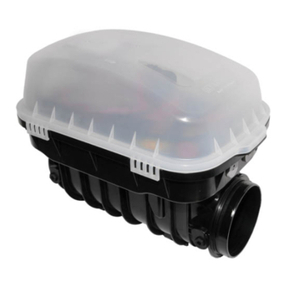
KESSEL-Ecolift
ist für durchgehende Ab-
wasserleitungen nach DIN EN 12056-
4/13564 Typ 3 bestimmt, an die Schmutz-
wasserleitungen sowie WC- und Urinal-
anlagen angeschlossen sind. Dadurch
wird eine sichere Entwässerung von Ab-
laufstellen unterhalb der Rückstauebene
auch während eines Rückstaus gewähr-
leistet. Die Pumpe arbeitet nur während
des Rückstaus und fördert das Schmutz-
wasser gegen den Rückstau über eine
Druckleitung, welche über die Rückstau-
ebene geführt werden muss in den Ka-
nal. Im rückstaufreien Betrieb wird das
Schmutzwasser durch das natürliche Ge-
fälle in den Kanal abgeleitet.
Ecoliftist kein Rattenschutz! Bei mögli-
chem Rattenbefall ist die Anlage bauseits
vor Beschädigungen zu schützen.
Wichtig:
Voraussetzung für einen einwandfreien
Betrieb ist
ein ausreichendes Gefälle in den Ab-
laufleitungen (Hinweis: Zwischen Zu-
und Ablauf besteht beim
Ecolift
ein
Gefälle von 9 mm)
ein hoher Wasseranteil im Abwasser,
damit der Selbstreinigungseffekt op-
timiert wird
eine ordnungsgemäße Verlegung
und vor allem Entlüftung der Zulauf-
leitung gemäß DIN EN 12056 / DIN
1986-100
mit fetthaltigen Abwasser nur mit er-
höhtem Wartungs- und Reinigungs-
aufwand möglich
Regenflächen bis max. 20 m2
2.2 Lieferumfang
Der Lieferumfang von KESSEL-Ecolift
besteht aus dem Grundkörper mit Pumpe
und Rückstauverschluss und den Elek-
tropaketen. Die Elektropakete bestehen
aus:
1. Zwei optischen Sonden und dem An-
triebsmotor
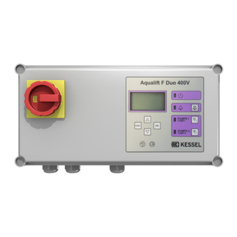
2. einem Schaltgerät mit Displayanzeige
(Netzanschluss 230 V, 50 Hz,Schutzart
IP 54) mit Batteriepufferung (2 x 9V)
zur Alarmmeldung bei Stromausfall.
3. Einer Einbau- und Bedienungsanlei-
tung
2.3 Vorgehen zur Installation
Während der Bauphase wird nur der
Grundkörper gemäß Kapitel 3 eingebaut
und angeschlossen. Ebenso wird in die-
ser Phase der Druckanschluss montiert.
In der Regel kann nicht direkt mit dem
anschließend durchzuführenden Elek-
troanschluß (Kapitel 4) und der nachfol-
genden Inbetriebnahme (Kapitel 5) fort-
gefahren werden. Bitte schließen Sie erst
bei Inbetriebnahme der KESSEL-Ecolift-
die elektrischen Anlagenkomponenten
(Pumpe, Sonden, Motor und Schaltgerät)
an. Bis dahin sind das beigelegte Elek-
tropaket und das Schaltgerät entspre-
chend trocken und sauber zu lagern. Die
Steckerendkappen erst bei Inbetriebnah-
me entfernen.
Es ist dringend darauf zu achten, die An-
lage stets mit Aufsatzstück und Deckel
bzw. der Schutzhaube bei freier Aufstel-
lung, zu verschließen, um eine Ver-
schmutzung der Anlage zu verhindern.
Achtung: Die Pumpe ist mit einem Trans-
portsicherheitsband gesichert, das vor In-
betriebnahme entfernt werden muss.
2.4 Allgemeine Hinweise zum Einbau
von Rückstausicherungen
Es ist nach DIN EN 12056 nicht zulässig,
alle Ablaufstellen eines Gebäudes – auch
die oberhalb der Rückstauebene (Straße-
noberkante) – über Rückstauverschlüsse
abzusichern, da beim geschlossenen Rück-
stauverschluss das Abwasser von oben
nicht mehr in den Kanal abfließen kann,
sondern nach dem Prinzip der kommuni-
zierenden Röhren zuerst aus den am tief-
sten installiertenAblaufstellen unterhalb der
Rückstauebene (i. a. R. Kellerräume) tritt
und damit den Keller überflutet.
Nur Ablaufstellen unterhalb der Rückstaue-
bene dürfen gegen Rückstau gesichert wer-
den. Alle Ablaufstellen oberhalb der Rück-
stauebene sind mit freiem Gefälle am Rück-
stauverschluss vorbei dem Kanal zuzulei-
ten.
Konsequenz: Getrennte Leitungsführung.
Häusliches Abwasser oberhalb der Rück-
stauebene kann somit in der Fallleitung ma-
ximal bis Höhe Straßenoberkante stehen
und nicht den Keller überfluten.
Regenwasser ist grundsätzlich nicht über
Rückstausicherungen abzuführen.
2.5 Druckanschluss
Der Verbau der Druckleitung ist gem. DIN
EN 12056 auszuführen. Druckanschluss:
11/2“ Außengewinde
das Druckleitungsset
(Art.-Nr. 28 040) enthält einen 5 m Druck-
leitungsschlauch DA 40 und einen Adapter
mit Rohrschelle. Alternativ kann ein Druck-
rohr D=40 mm mind. 38 mm für die PVC-
Klebeverbindung verwendet werden. Die
Druckleitung ist mittels einer
Rückstauschleife über die örtlich festge-
legte Rückstauebene zu führen und unmit-
telbar an eine erweiterte (mind. DN 70)
belüftete Grund- oder Sammelleitung an-
zuschließen. Drucklose Rohranschlüsse
(z.B. HT-Rohr) sind nicht für Druckleitun-
gen
zulässig.
Freie Rohrleitung:
Diese Druckleitung wird vom Installateur
montiert und fest fixiert, so dass jedoch
eine spätere Abkopplung vom Ecolift-
möglich ist.
Falsch!
Richtig!
Rückstausicherung
Rückstausicherung
Einbau einer Rückstausicherung an der falschen Stelle
Einbau einer Rückstausicherung an der richtigen Stelle
Rückstau-
ebene
Rückstau-
ebene
