manuals.online logo
Brands
  1. Home
  2. •
  3. Brands
  4. •
  5. Kessel
  6. •
  7. Control Unit
  8. •
  9. Kessel EUROFIX Clausio User manual

Kessel EUROFIX Clausio User manual

ANLEITUNG FÜR EINBAU, BEDIENUNG UND WARTUNG
EUROFIX c ausio®
Name/Unterschrift Datum Ort Stempel Fachbetrieb
Insta ation
der An age wurde durchgeführt von Ihrem Fachbetrieb:
Inbetriebnahme Einweisung
Änderungsstand: 11/2009
Sachnummer: 153-045
Techn. Änderungen vorbehalten
Rückstauverschluss • Rioolkeerklep
Dispositif anti-refoulement
Valvola anti-riflusso • Non return valve
Einbau- und Bedienungsvorschriften Seite 2/7-9
Inbouw-en insta atie-voorschriften Pagina 3/7-9
Instructions de montage
et mode d’emp oi Page 4/7-9
Avvertenze di montaggio e
istruzioni per ’uso Pagina 5/7-9
Insta ation and operating
instructions Page 6/7-9
D
NL
F
I
GB
EN 13564
Typ 2
DIN EN 13564 Typ 1
EUROFI Clausio®
Sehr geehrter Kunde
wir freuen uns über Ihre Wahl und das ent-
gegengebrachte Vertrauen in den EURO-
FIX clausio®Rückstauverschluss. Wir sind
sicher, dass dieses, nach höchsten Qua-
litätsnormen gefertigte Produkt jederzeit
zu Ihrer Zufriedenheit funktionieren wird.
Einsatzgebiete
Der in durchgehende Rohrleitungen in-
stallierte EUROFIX clausio®Rückstauver-
schluss verhindert zuverlässig das Zu-
rückfließen von Abwasser bei auftreten-
dem Rückstau.
Er ist stets in betriebsfähigem Zustand zu
halten und muss jederzeit gut zugänglich
sein.
Technische Beschreibung
Der Rückstauverschluss EUROFIX clau-
sio®ist aus korrosionsfreiem, schlag-
zähem Kunststoff gefertigt. Die Abdeck-
platte ist sowohl tagwasser-, als auch ge-
ruchsdicht und zusätzlich mit einer Dieb-
stahlsicherung ausgestattet.
Der Betriebsverschluss (Klappe) ist stän-
dig geschlossen und öffnet selbsttätig bei
abfließendem Wasser. it dem Notver-
schluss kann die Leitung durch Hand-
betätigung verschlossen werden.
Der Deckel des Rückstauverschlusses
kann ohne Werkzeug demontiert werden.
Damit ist für leichte Zugänglichkeit sowie
Wartungen und Reinigung gesorgt.
Nach Demontage des Deckels und der
Klappe kann der Rückstauverschluss als
Reinigungsrohr verwendet werden (freier
Rohrquerschnitt).
it dem teleskopischenAufsatzstück lässt
sich Höhe und Niveau stufenlos an den
fertigen Oberflächenendbelag angleichen.
In Verbindung mit einem Zwischenstück
(Best. Nr. 67500) ist jede erforderliche Ein-
bautiefe zu erreichen. SowohlAufsatz-, als
auch Zwischenstück können durch Absä-
gen auf beliebige Höhe gekürzt werden.
Die vollständige Dichtheit des Gerätes
wird durch die Abdichtung der einzelnen
Teile gewährleistet.
In Verbindung mit einem Tragerahmen aus
Kunststoff PVC (Best. Nr. 27180) ist der
EUROFIX clausio®bis 1,5 t befahrbar. Bei
Heissbitumenbelag muss der Tragerah-
men aus Guss (Best. Nr. 27181) verwen-
det werden.
Einbauhinweise
• Anschließen der Rohrleitung (Ab-
flußrichtung beachten!)
• Einbetten in Rohbeton
• Beim Einbau des Grundkörpers muss
nicht auf die Einbautiefe geachtet wer-
den. it dem teleskopischen Aufsatz-
stück kann die Aufbauhöhe an den
Oberflächenendbelag stufenlos angegli-
chen werden.
ACHTUNG: Bei sich nachsenkendem
oder setzendem Oberflächenbelag
genügend Abstand zwischen Aufsatz-
stück und Grundkörper lassen, damit
sich das Aufsatzstück mit absenken
kann.
• Zum vertieften Einbau Zwischenstücke
verwenden.
D
2
3
EUROFI Clausio®
Geachte klant,
Wij verheugen ons over uw keus en het
door u gestelde vertrouwen in de
EUROFIX clausio®rioolkeerklep. Wij zijn
er zeker van, dat dit volgens de hoogste
kwaliteitsnormen vervaardigde produkt, tot
uw volle tevredenheid zal funktioneren.
Toepassingsmogelijkheden
De in de doorgaande leidingen
geïnstalleerde EUROFIX clausio®riool-
keerklep voorkomt het terugstromen van
afvalwater bij optredende terugstuw.
Hij dient steeds bedrijfsklaar te zijn en moet
altijd goed toegankelijk gehouden worden.
Technische beschrijving
De rioolkeerklep EUROFIX clausio®is van
een corrosievrije slagvaste kunststof
vervaardigd. Het deksel is zowel water- als
stankdicht en extra voorzien van een
knevelbare afsluiting.
De keerklep is permanent gesloten en
opent zich automatisch bij de toevoer van
afvalwater. et de noodvergrendeling kan
de leiding via handbediening worden
gesloten. De deksel van de keerklep-unit
kan zonder gereedschap verwijderd
worden. Daarmee is gezorgd voor een
makkelijke toegankelijkheid voor zowel
onderhoud als reiniging.
Na verwijdering van de deksels en de
keerklep kan de EUROFIX clausio®als
ontstoppingsstuk gebruikt worden (vrije
doorgang).
et het teleskopisch opzetstuk laat zich
hoogte en niveau traploos aan het reeds
bestaande oppervlak aanpassen. Samen
met een tussenstuk (Best. nr. 67500) is
iedere gewenste inbouwdiepte te bereiken.
Zowel opzet- als tussen-stuk kunnen door
afzagen naar goeddunken op de gewenste
lengte afgekort worden.
De volledige dichtheid van het hulpstuk
wordt door de afdichtingen van ieder
afzonderlijke deel gewaarborgd.
Samen met een rand van kunststof PVC
(Best. nr. 27180) is de EUROFIX clausio®
tot 1,5 ton wieldruk berijdbaar.
Bij een wegdek van asfalt moet een
gietijzeren rand toegepast worden (Best.
nr. 27181).
Inbouwvoorschriften
• Aansluiting van de afvoerleiding
• Storten in ruwbeton
• Bij inbouw van het basiselement hoeft
niet op de inbouwdiepte gelet worden.
et het teleskopische opzetstuk kan de
opbouw traploos aan het oppervlak
aangepast worden.
LET OP: Bij later optredende grond-
zettingen voldoende afstand tussen
opzetstuk en basiselement houden, zodat
het opzetstuk mee kan zakken.
• Voor diepere inbouw tussenstukken
gebruiken
NL
4
EUROFI Clausio®
Cher client,
nous sommes bien contents de votre choix
et de la confiance que vous affichez envers
le dispositif anti-refoulement EUROFIX
clausio®. Nous sommes bien sûrs et certains
que ce produit, qui a été fabriqué seion des
normes de qualité excellentes, fonctionnera
à tout moment et à votre satisfaction.
Domaines d’application
Le dispositif anti-refoulement EUROFIX
clausio®, qui a été installé dans les
conduites continues, empêche dʼune
manière sûre le reflux des eaux usées sʼil y
a des retenues.
Il doit être toujours prêt à être mis en marche
et être dʼun accès facile.
Description technique
Le dispositif anti-refoulement EUROFIX
clausio®est fabriqué en matière plastique
exempt de matérieux corrosifs il est deté
dʼune résilience appropriés. Les plaques de
recouvrement ne permettent ni à lʼeau
superficielle, ni aux odeurs de sʼéchapper.
Elles ont été munies en outre dʼun anti-vol.
Lʼobturateur de service (clapet) est toujours
fermé et sʼouvre tout seul si lʼeau coule. A
lʼaide de lʼobturateur de secours on peut
fermer la conduite à la main. Le couvercle du
dispositif anti-refoulement peut être
démonté sans aucun outil. Ainsi
lʼaccessibilité, lʼentretien et le nettoyage sont
faciles.
On peut employer le dispositif anti-
refoulement en tant que conduite de
nettoyage après avoir démonté le couvercle
et le clapet.
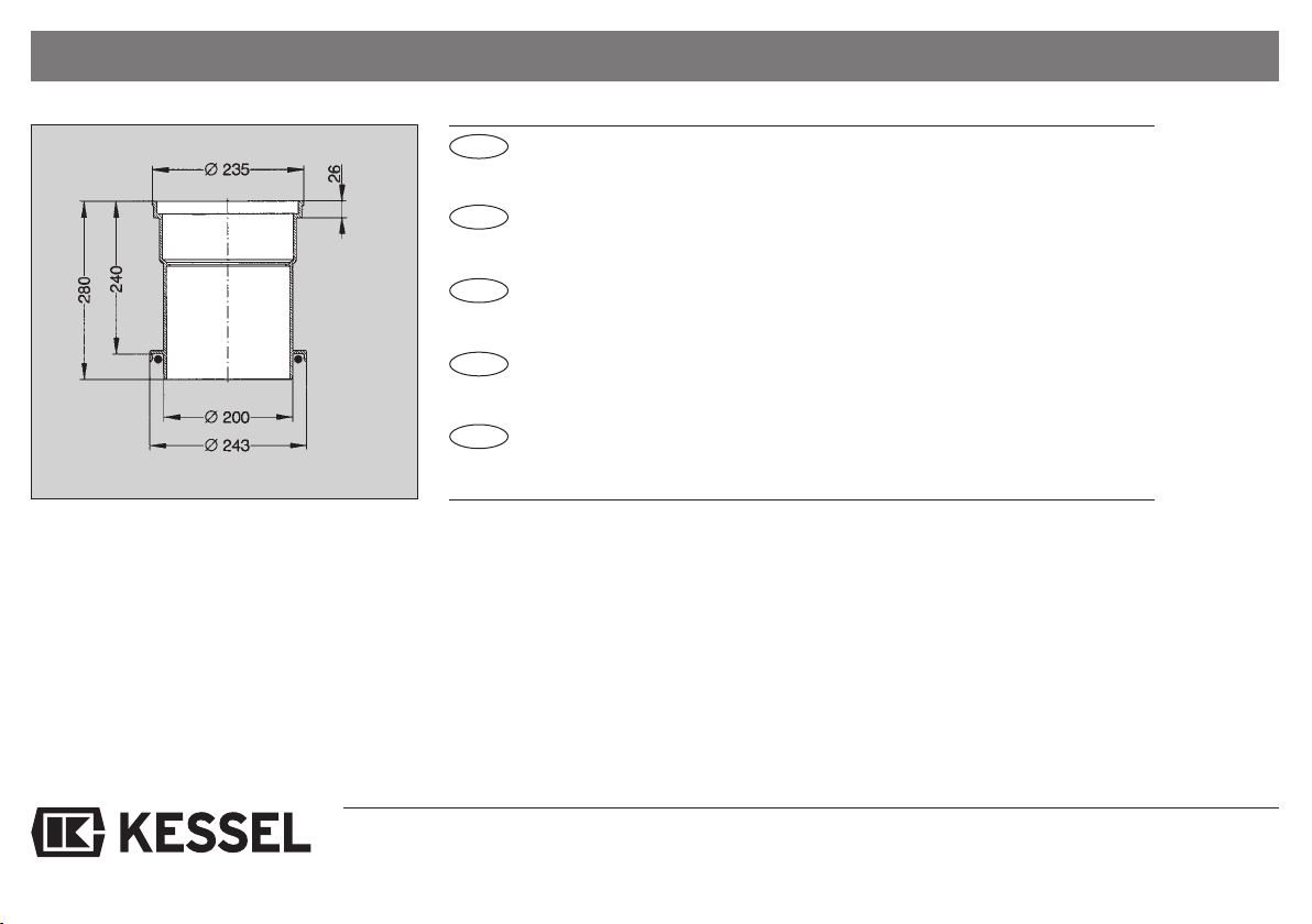
On peut harmoniser aussi dʼune manière
continue les hauteurs et les niveaux partiels
à lʼaide de la soupape téléscopique aux
couches de surface sur place. A lʼaide dʼune
pièce intercalaire (numéro de commande
67500) on peut obtenir chaque profondeur
nécessaire pour le montage. On peut
raccourcir la hauteur de la soupape ainsi
que celle de la pièce intercalaire de
nʼimporte quelle manière après les avoir
sciées.
Lʼétanchéité complète de lʼoutil est garantie
par lʼétoupement des différentes parties.
LʼEUROFIX clausio®est viable jusquʼà 1,5 t
si on utilise un cadre porteur en matière
plastique PVC (numéro de commande
27180). Si on a des couches de bitume
chaudes, il faut employer un cadre porteur
de coulée.
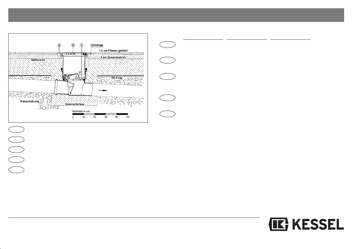
Indications de montage
• Raccord de la conduite (faire attention à la
direction de la vole dʼécoulement)
• Insérer dans le béton brut
• Il ne faut pas faire attention lors du
montage du corps principal à la
profondeur de lʼencastrement. On peut
harmoniser dʼune manière continue la
hauteur du montage à lʼaide de la soupape
téléscopique aux couches de surface.
ATTENTION: Laissez sʼil vous plait un
écert suffisent entre la soupape et le corps
principal si la couche de surface sʼabsisse
ou sʼarrête afin que la soupape puisse être
mise à un niveau inférieur.
• Utilisez des pièces intercalaires pour un
montage en retrait
F
5
EUROFI Clausio®
Gentile cliente
Siamo lieti della sua scelta e della fiducia
accordata alla valvola anti-riflusso
EUROFIX clausio®. Siamo certi che il
funzionamento di questo prodotto, che è
stato creato rispettando le più esigenti
norme di qualità, sarà sempre in grado di
soddisfare le sue esigenze.
Campi d’impiego
EUROFIX clausio®installato in condutture
di tubi passanti evita con alta affidabiltà il
riflusso di acque di scarico in caso di un
ristagno.
Lʼimpianto deve essere continuamente
pronto allʼuso e sempre accessibile.
Descrizione tecnica
La valvola anti-riflusso EUROFIX clausio®
é prodotta in materiale plastico resistente
alla corrosione ed agli urti. La piastra di
copertura è stagna allʼacqua superficiale
ed agli odori ed è inoltre munita di un
impianto antifurto.
La chiusura di servizio (valvola) è sempre
chiusa e si apre automaticamente in caso
di afflusso di acque di scarico. Tramite la
chiusura di emergenza la conduttura può
essere chiusa manualmente.
Per lo smontaggio del coperchio della
valvola anti-riflusso non occorrono utensili.
Cosi è garantito lʼaccesso facile e la
semplice pulizia e manutenzione.
Dopo lo smontaggio del coperchio e della
valvola EUROFIX clausio®può essere
usato come tubo di pulizia (libero diametro
del tubo).
Lʼaltezza ed il livello dellʼimpianto possono
essere adeguati alla superficie definitiva a
variazione continua con lʼaiuto
dellʼelemento telescopico di rialzo.
Qualsiasi profondità di installazione può
essere raggiunta con la combinazione di
un pezzo intermedio (numero dʼordine
67500). Sia lʼelemento di rialzo sia il pezzo
intermedio possono essere accorciati
tramite asportazione con sega.
La totale tenuta ermetica dellʼimpianto è
garantita dalla impermeabilizzazione delle
singole parti.
In combinazione con un telaio portante di
plastica PVC (numero dʼordine 27180)
EUROFIX clausio®puo sopportare pesi
fino a 1,5 t. In caso di una pavimentazione
bituminos a caldo deve essere usato il
telaio portante in ghisa (numero dʼordine
27181).
Istruzioni per l’installazione
• Allacciamento della conduttura
(osservare la direzione di scarico)
• Annegamento con calcestruzzo
• Installando la parte di base la profondità
di installazione può essere trascurata.
Lʼaltezza definitiva può essere adeguata
a variazione continua alla superficie
tramite un elemento telescopico si rialzo.
ATTENZIONE: In caso di superfici
cedenti lasciare abbastanza spazio tra la
parte base e lʼelemento di rialzo per
permettere così lʼabbassamento
dellʼelemento di rialzo.
• Per lʼinstallazione in profondità usare la
prolonga.
I
6
EUROFI Clausio®
Dear customer
Thank you for choosing the EUROFIX
clausio®non-return valve. We are sure that
this product, manufactured to the highest
quality standards, will provide you with
many years of reliable service.
Applications
When installed in continuous pipe systems,
the EUROFIX clausio®non-return valve
reliably counters the potential backflow
effect of effluent in the event of backwater.
It should always be kept fully operational
and must always be easily accessible.
Technical description
The EUROFIX clausio®non-return valve is
made of non-corroding, impact-resistant
plastic. The cover is both water and odour
tight, and also has an anti-theft device.
The service valve (gate) is normally closed,
opening automatically when effluent is
discharged. The line can be closed
manually at the emergency gate.
The cover of the non-return valve can be
dismantled without any tools, provided it is
easily accessible, properly maintained and
cleaned.
With the cover and gate dismantled, the
non-return valve can be used as a cleanout
(tube diameter unobstructed).
The height and level can be adjusted
steplessly to the final ground level via the
vertically adjustable upper section. In
conjunction with an intermediate section
(Order No. 67500), any desired installation
depth can be reached. Both the upper and
intermediate sections can be cut off to the
desired height.
The system is guaranteed to be leak-proof
since each individual component is sealed.
In conjunction with a PVC plastic support
frame (Order No. 27180), vehicles
weighing up to 1.5 tons can drive over the
EUROFIX clausio®if installed beneath a
hot-bitumen surface, the cast iron support
frame (Order No. 27181) must be used.
Notes on installation
• Connect up the pipe (noting direction of
effluent flow).
• Embed in concrete.
• The installation depth of the basic unit is
not critical. The final ground level can be
reached with the aid of the vertically
adjustable upper section.
I PORTANT:if the surface is expected to
settle, ensure that there is sufficient space
between the upper section and basic unit
so that the upper section can settle along
with with surface.
• Use intermediate sections for deeper
installation.
GB
7
Einbau • Inbouw • Montage • Montaggio • Installation
EUROFIX clausio
®
Rückstauverschluß
EUROFIX clausio
®
Rioolkeerklep
EUROFIX clausio
®
Dispositif anti-
refoulement
EUROFIX clausio
®
Valvola anti-riflusso
EUROFIX clausio
®
non-return valve
Höhenverstellbares
Aufsatzstück
In hoogte verstelbaar
opzetstuk
Déplacement vertical
de le soupape
Rialzo telescopico
Vertically adjustable
upper section
Abdeckplatte
Ø 200 mm Klasse K
Deksel Ø 200 mm
klasse K
Plaque de recouvre-
ment Ø 200 mm
Grosseur K
Piastra di copertura
Ø 200 mm classe K
Cover Ø 200 mm class
K (300 kilos)
Abdeckplatten-Demontage Entriegeln und Lösen durch Drehen der Verschlüsse um 180° gegen den Uhrzeigersinn.
Deksel demontage Onsluiten en verwijderen door het verdraaien van de knevel met 180° tegen de klok in.
Demontage de la Plaque de recouvrement Déblocage et desserage des obturateurs: à 180 degré dans le sene inverse des aiguilles dʼune montre.
Smontaggio della piastra di copertura Sbloccare girando la chiusure di 180° in senso antiorario.
Removing the cover Disengage and release by turning the cover locks counterclockwise 180°.
D
D
NL
F
I
GB
NL
F
I
GB
햲 햳 햴
8
Deckelmontage • Dekselmontage • Montage du couvercle • Montaggio del coperchio • Cover Mounting
• Deckeldichtung mit Gleitmittel bestreichen
• Prüfen ob Klappe in Führung sitzt 햲
• Verriegelungshebel (schwarz) Stellung A
• Notverschluss (rot) Stellung „Auf“ B
• Deckel, Pfeile in Abflussrichtung, in Halterung einführen und fest nach unten drücken 햴
• Afdichtingsring van deksel met glijmiddel insmeren
• Controleren of de klep in de geleidine zit 햲
• Vergrendeling (zwart) stand A
• Noodvergrendeling (rood) stand „open“ B
• Deksel met pijlen in de afvoerrichting in de houder steken en stevig naar onderen drukken 햴
• Le joint du couvercle est à enduire de lubrifiants.
• Contrôlez si le clapet est dans la conduite 햲
• Levier de blocage (noir) – Position A
• Obturateur de secours (rouge) – Position B
• Couvercle, flèches dans la direction du dechargeoir. Introduire dans lʼattache et appuyer fort
vers le bas 햴
• Spalmare di lubrificante la guarnizione del coperchio
• Verificare se la valvola é inserita nella guida 햲
• Leva di blocco (nero) in posizione A
• Chiusura di emergenza (rosso) in posizione B
• Inserire il coperchio, frecce in direzione di scarico, nel supporto spingendo con forza verso il
basso 햴
• Coat cover seal with lubricant
• Check whether flap is located in guide, 햲
• ove locking lever (black) to position A
• ove emergency lever (red) to position ”open“, B
• Insert the cover in the holder with the arrows in the direction of flow and press down firmly, 햴
• Insert double guides into double brackets. Firmly push down opposite side of cover and lock
shut with black lever.
NL
F
I
GB
햲
햳
햴
D
9
Beschreibung • Beschrijving • Description • Descrizione • Description
Eurofix clausio
®
DN 100 74100.10
mit teleskopischem Aufsatzstück
DN 125 74125.10
DN 150 74150.10
Eurofix clausio
®
Ø 110 74100.10
met teleskopisch opzetstuk
Ø 125 74125.10
Ø 160 74150.10
Eurofix clausio
®
Ø 110 74100.10
à soupape téléscopique
Ø 125 74125.10
Ø 160 74150.10
Eurofix clausio
®
Ø 110 74100.10
con rialzo telescopico
Ø 125 74125.10
Ø 160 74150.10
Eurofix clausio
®
Ø 110 74100.10
with vertically adjustable upper section
Ø 125 74125.10
Ø 160 74150.10
Maße • Maat • Mesures • Dimensioni • Dimensions
Best.-Nr. 74100.10
L = 340 mm H1 = 161 mm H2 = 181 mm
Best.-Nr. 74125.10
L = 340 mm H1 = 161 mm H2 = 181 mm
Best.-Nr. 74150.10
L = 378 mm H1 = 144 mm H2 = 164 mm
D
NL
F
I
GB
10
Beschreibung • Beschrijving • Description • Descrizione • Description
D
NL
F
I
GB
Zwischenstück 67500
Zwischenstück aus Kunststoff PVC mit Rollring
Vergrößert die Einbautiefe um 240 mm
Tussenstuk 67500
Tussenstuk van kunststof PVC, met afsluitring,
vergroot de inbouwdiepte met 240 mm
Pièce intercalaire 67500
Pièce intercalaire en plastique PVC à anneaux à roulettes
agrandit la profondeur du retrait dʼà peu près 240 mm
Elemento intermedio 67500
Elemento intermedio in plastica PVC con anello a rulli per
aumenta la profondità di installazione di 240 mm
Intermediate section 67500
Intermediate section in PVC plastic with gasket seal,
increases installation depth by 240 mm
11
Beschreibung • Beschrijving • Description • Descrizione • Description
D
NL
F
I
GB
Tragerahmen
Tragerahmen aus Kunststoff PVC. Befahrbar bis 1,5 t.
27180
Tragerahmen aus Guss. Zu verwenden bei Oberflächen aus
27181
Heissbitumen.
Rand
Rand van kunststof PVC. Wieldruk tot 1,5 ton.
27180
Rand van gietijzer. Toe te passen bij wegdek van asfalt.
27181
Cadre de support
Cadre de support en plastique PVC viable jusquʼà 1,5 t.
27180
Cadre de support en coulée. A utiliser si on a des couches
27181
de bitume chaudes.
Telaio portante
Telaio portante in plastica PVC, sopporta pesi fino a 1,5 t.
27180
Telaio portante in ghisa per superfici di bitume a caldo.
27181
Support frame
Support frame in PVC plastic, supports vehicles weighing up to 1.5 t.
27180
Cast iron support frame: for use with hot-bitumen surfaces.
27181
A es für die Entwässerung
Rückstauversch üsse
Hebean agen
Ab äufe / Rinnen
innerha b von Gebäuden
Ab äufe
außerha b von Gebäuden
Abscheider
Fettabscheider
Ö -/Benzinabscheider
Stärkeabscheider
Sinkstoffabscheider
K eink äran agen
Schächte
Regenwassernutzan agen
K
K
K
K
K
K

This manual suits for next models

3

Other Kessel Control Unit manuals

Kessel Pumpfix F Comfort Installation instructions

Kessel

Kessel Pumpfix F Comfort Installation instructions

Kessel 28 683 Manual

Kessel

Kessel 28 683 Manual

Kessel Ecolift User manual

Kessel

Kessel Ecolift User manual

Kessel Staufix Series User manual

Kessel

Kessel Staufix Series User manual

Kessel Pumpfix F Standard Installation instructions

Kessel

Kessel Pumpfix F Standard Installation instructions

Kessel Staufix Programming manual

Kessel

Kessel Staufix Programming manual

Kessel Staufix SWA User manual

Kessel

Kessel Staufix SWA User manual

Kessel Aqualift F Comfort 400V Series User manual

Kessel

Kessel Aqualift F Comfort 400V Series User manual

Kessel Aqualift Comfort 230V Mono User manual

Kessel

Kessel Aqualift Comfort 230V Mono User manual

Kessel Comfort PLUS User guide

Kessel

Kessel Comfort PLUS User guide

Kessel Staufix FKA User manual

Kessel

Kessel Staufix FKA User manual

Kessel Aqualift Comfort 230V Duo Owner's manual

Kessel

Kessel Aqualift Comfort 230V Duo Owner's manual

Kessel Staufix Series User manual

Kessel

Kessel Staufix Series User manual

Kessel Staufix SWA User manual

Kessel

Kessel Staufix SWA User manual

Kessel Comfort PLUS User manual

Kessel

Kessel Comfort PLUS User manual

Kessel SG 400 V Mono Quick start guide

Kessel

Kessel SG 400 V Mono Quick start guide

Kessel 28701X User manual

Kessel

Kessel 28701X User manual

Kessel Staufix DA 100 User manual

Kessel

Kessel Staufix DA 100 User manual

Kessel 80072 User manual

Kessel

Kessel 80072 User manual

Kessel Comfort PLUS User manual

Kessel

Kessel Comfort PLUS User manual

Kessel Staufix User manual

Kessel

Kessel Staufix User manual

Kessel Staufix FKA Standard User manual

Kessel

Kessel Staufix FKA Standard User manual

Kessel Staufix SWA User manual

Kessel

Kessel Staufix SWA User manual

Kessel 52101 User manual

Kessel

Kessel 52101 User manual

Popular Control Unit manuals by other brands

Victron energy Venus GX manual

Victron energy

Victron energy Venus GX manual

turck TBEN-S Series Instructions for use

turck

turck TBEN-S Series Instructions for use

Sonnen KNX manual

Sonnen

Sonnen KNX manual

LUXMATE LM-RV quick start guide

LUXMATE

LUXMATE LM-RV quick start guide

Emerson Alco Controls M36 Series Operating	 instruction

Emerson

Emerson Alco Controls M36 Series Operating instruction

Westport OMVL DREAM XXI E MP48 installation manual

Westport

Westport OMVL DREAM XXI E MP48 installation manual

CARLO GAVAZZI Certus CM22D0A instruction manual

CARLO GAVAZZI

CARLO GAVAZZI Certus CM22D0A instruction manual

Zodiac Jandy Pro Series JXi R0589700 instructions

Zodiac

Zodiac Jandy Pro Series JXi R0589700 instructions

Siemens SIRIUS ACT 3SU14 Original operating instructions

Siemens

Siemens SIRIUS ACT 3SU14 Original operating instructions

Pickering PXI 40-664A user manual

Pickering

Pickering PXI 40-664A user manual

Sloan Optima Plus EBV-500-A installation instructions

Sloan

Sloan Optima Plus EBV-500-A installation instructions

AVK 54 Series Installation, operation & maintenance manual

AVK

AVK 54 Series Installation, operation & maintenance manual

Pima MWA500 installation guide

Pima

Pima MWA500 installation guide

Lenze E94AYAD-SM300 Mounting instructions

Lenze

Lenze E94AYAD-SM300 Mounting instructions

Kemppi DIGITAL CONNECTIVITY MODULE operating manual

Kemppi

Kemppi DIGITAL CONNECTIVITY MODULE operating manual

Honeywell Ex-Or CDH8U5 Installation and commissioning instructions

Honeywell

Honeywell Ex-Or CDH8U5 Installation and commissioning instructions

Girard Systems 98GCK-16 manual

Girard Systems

Girard Systems 98GCK-16 manual

Roland D-110 owner's manual

Roland

Roland D-110 owner's manual

manuals.online logo
manuals.online logoBrands
  • About & Mission
  • Contact us
  • Privacy Policy
  • Terms and Conditions

Copyright 2025 Manuals.Online. All Rights Reserved.