KI Lancaster Auditorium Seating User manual

Assembly Instructions
Lancaster® Auditorium Seating with Power & Data
December 2020

Lancaster®Auditorium Seating with Power & Data - Table of Contents
Assembly Instructions
Specifications..........................................................................................................................................1
Preliminary Mounting .............................................................................................................................2
Upright Identification...............................................................................................................................3
Upright Installation..................................................................................................................................4
Standard & Bariatric Back Attachment.....................................................................................................5
Power & Data Module and Power Infeed Installation...............................................................................6
Data Infeed Installation............................................................................................................................7
Power & Data Distribution.......................................................................................................................8
Power & Data Wireway Cover Installation ..............................................................................................9
Power & Data Side Cover Installation ...................................................................................................10
End Panel & Aisle Light Installation......................................................................................................11
Standard & Bariatric Seat Installation....................................................................................................12
ADA Removable Base Installation..........................................................................................................13
ADA Flip-Arm, Cap, End Panel & Aisle Light Installation......................................................................14
Hardware Overview ...............................................................................................................................15
Wire Diagrams ......................................................................................................................................16

Lancaster® Auditorium Seating with Power & Data
Assembly Instructions
Assemble units as described herein only. To do otherwise
may result in instability. All screws, nuts and bolts must be
tightened securely and must be checked periodically after
assembly. Failure to assemble properly, or to secure parts
may result in assembly failure and personal injury.
1
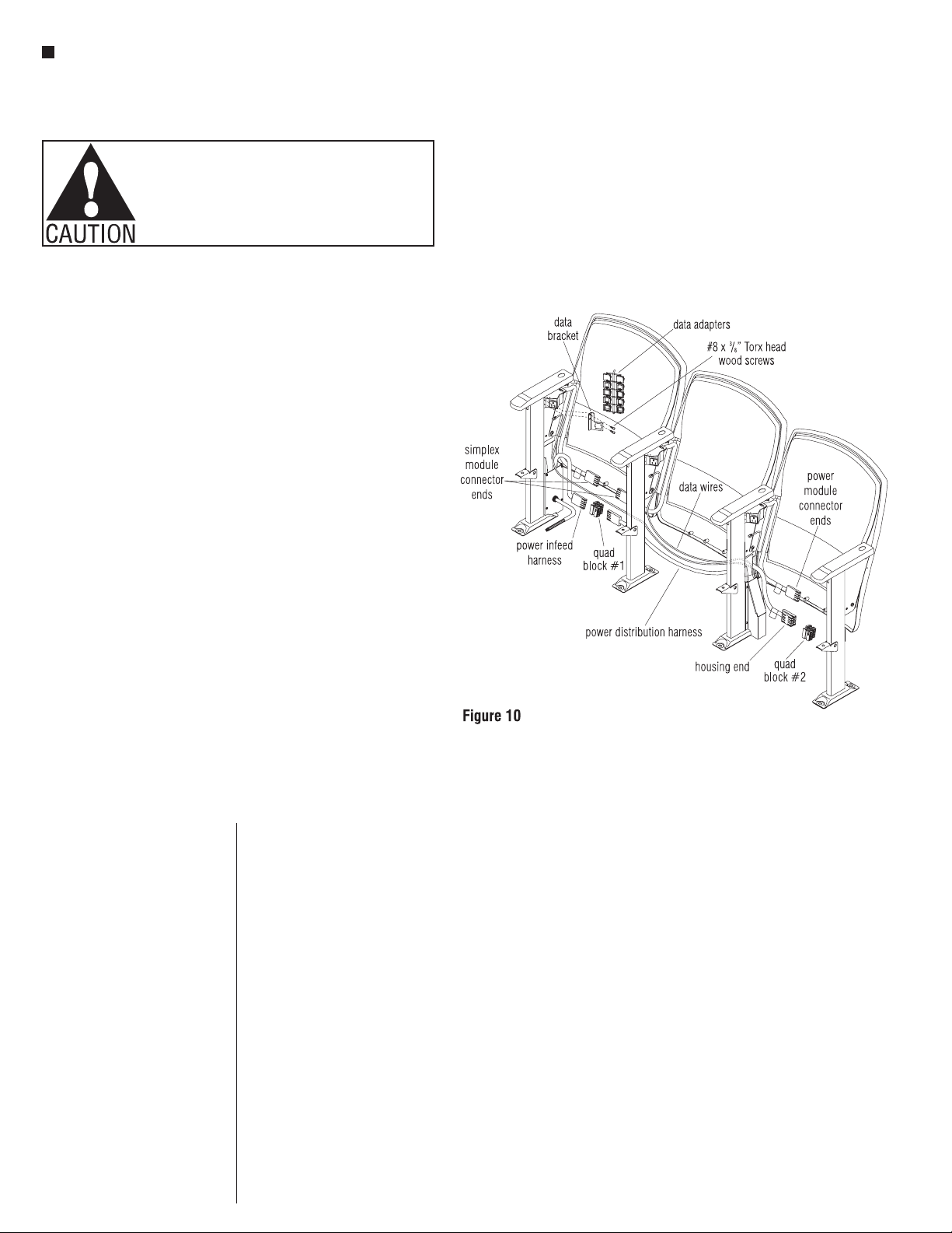
11. Attach power & data modules,
electrical components, data
wires and data jacks (optional).
Note: If unit is powered, the end
panel is installed at the same time
as the above items.
12. Attach and route the power
& data infeed connections
(optional).
13. Attach side covers (required with
power & data or optional without
power & data).
14. Attach end panel (required with
power & data or optional without
power & data).
15. Install the seats.
16. Tighten floor anchors.
17. Install ADA removable bases
(optional).
Note: ADA bases are not
available with power & data.
18. Mount row and seat numbering
(optional).
19. Clean product and site.
20. Walk through with installation
crew to assure the product has
been installed per Lancaster
Auditorium Seating Assembly
Instructions and space-planning
layout.
21. Perform final walk through with
the customer. Receive sign-off.
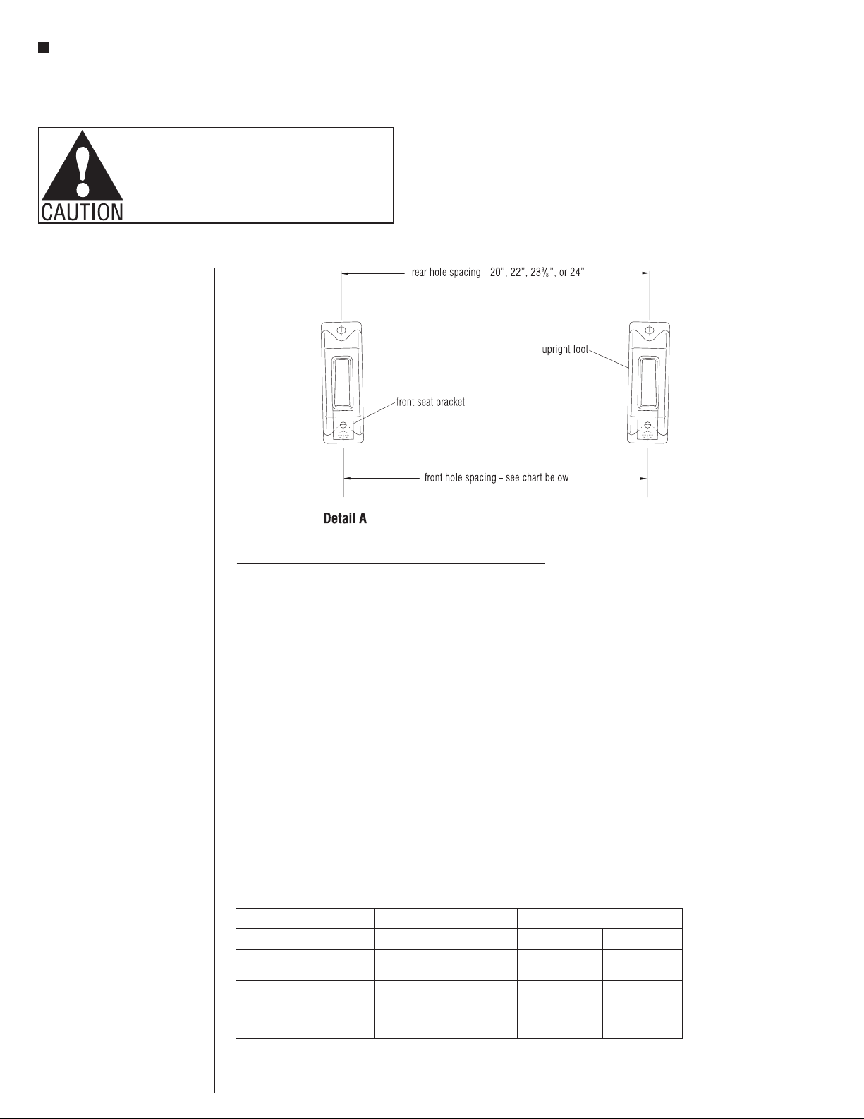
Note: Dimensional spacing
referenced is centerline to
centerline unless otherwise noted.
Concrete Floors
• 5⁄16 -18 or 3⁄8-16 grade 5
expansion anchors
• Standard flat washers, plated
• LockTite (red) thread lock or
equal
• Two screw assemblies
required per upright
Note: Floor-mounting fasteners are
not provided.
Steps For Installation
1. Read and review Lancaster
Auditorium Seating Assembly
Instructions.
2. Review space-planning layouts.
3. Review job site and verify
field conditions.
4. Verify floor structural
conditions.
5. Stage product for installation.
6. Locate and mark layout
reference points.
7. Locate and drill upright holes
into floor.
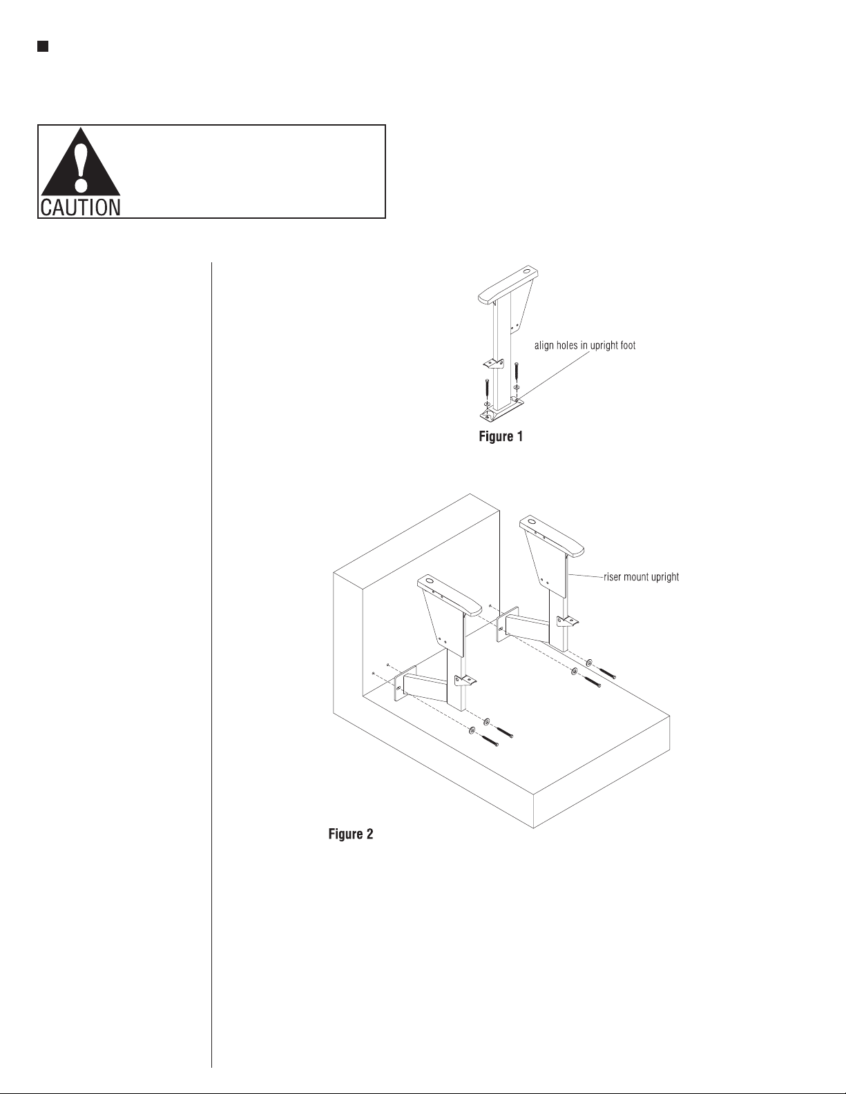
8. Attach uprights to the floor,
following the space-planning
layout. Install anchor bolts (not
provided) loosely to allow for
adjustment.
9. Attach backs to the uprights.
Refer to the space-planning
layout to determine location of
sizes and which top hole should
be used on the back bracket
(to determine the back angle)
(center hole is standard).
Note: Optional power & data
components should be installed
before the seats are assembled.
10. Install aisle light tube and
housing (optional).
Note: Read these assembly
instructions carefully prior to
product installation. Electrically
interconnected furnishings
must also be mechanically
interconnected. Product failure
and personal injury may result if
instructions are not followed.
Minimum Construction
Required For Upright
Installation
Wood Floors
• Minimum two layers of 3⁄4”
thick plywood
• APA rated grade plywood
• Allow minimum embedment
11⁄2” with lag screws
• Use toggle bolt if less than
11⁄2” embedment
Concrete Floors
• 3000 psi concrete
compressive strength
• 3” thick free of obstructions
for 11⁄2”
• 4” thick for riser mount free of
obstruction for 21⁄2”
• Riser to be plumb within 1⁄8°
• Minimum anchor embedment
11⁄2”
Note: Warranty null and void if KI
Lancaster Seating product line is
installed on flooring not meeting
minimum structural requirements
stated above.
Floor Fastener Requirements
Wood Floors
•5⁄16” x 13⁄4” lag bolts
• Grade 5
• 5⁄16” flat washers
• 3⁄8” toggle bolts
• All hardware to be plated
• Two bolt assemblies required
per upright
Tools Required:
• Hammer drill and bit for concrete
anchor holes
• Drill and bit for pilot holes in
wood floors
• Torx 27 head for back screws and
end panels
• Torx 20 head for electrical covers
• 9⁄16” deep well socket with ratchet
• 7⁄16” open-faced wrench
• 9⁄16” open-faced wrench
• Chalk line
• Tape measure
• Torque wrench

2
Lancaster®Auditorium Seating with Power & Data
Assembly Instructions
Assemble units as described herein only. To do otherwise
may result in instability. All screws, nuts and bolts must be
tightened securely and must be checked periodically after
assembly. Failure to assemble properly, or to secure parts
may result in assembly failure and personal injury.
Preliminary Mounting
Hole Layout
1. Follow the space-planning layout
provided and determine where
uprights with and without tablet
arms are located.
Note: On radiused installations,
the front slots of the upright are
shifted closer together. Rear slots
always remain at the appropriate
dimension matching the seat size:
20”, 22”, 233/8”, or 24” (Detail
A, “Radius Chart” and
“Tolerances for Mounting
Uprights”).
2. Carefully locate the upright
mounting holes and the
appropriate floor anchors as
specified in the space-planning
layout provided. Study “Detail A”,
the guidelines in the “Radius
Chart” and “Tolerances for
Mounting Uprights.”
Radius Chart
The chart is a guide to front slot,
center-to-center dimensions for
specific radius installations. This
dimension can be measured from
front bracket to front bracket. Rear
slot center-to-center dimension
must remain at 20”, 22”, 233/8”,
or 24” for straight runs and radius
installations. For a radius of 40’ or
less, 1⁄8” is added to nominal
center-to-center spacing of rear
slots.
RADIUS CHART – Front Hole Spacing for Upright Foot
Radius (ft) 20” Seat 21” Seat 22” Seat 23” Seat 24” Seat
20’* 1919/32” 2025/32” 21-19/32” 2225/32” 2319/32”
25’* 1923/32” 2029/32” 2123/32” 2229/32” 2323/32”
30’* 1925/32” 21” 2125/32” 23” 2325/32”
40’* 197/8” 213/32” 217/8” 233/32” 237/8”
60’ 1927/32” 213/16” 2127/32” 233/16” 2327/32”
100’ 1929/32” 211/4” 2129/32” 231/4” 2329/32”
200’ 1915/16” 215/16” 2115/16” 235/16” 2315/16”
300’ 1931/32” 2111/32” 2131/32” 2311/32” 2331/32”
400’-straight 20” 213/8” 22” 233/8” 24”
*1/8” is added to nominal center-to-center spacing of rear slots.
Note: See space-planning layout for specific anchor bolt locations per seat, per row. The chart dimensions are
a reference to aid in upright alignment.
Note: For seating with tablet arms, use the dimensions from the chart above. Tablet arms cannot be installed
on a radius less than 30 ft.
TOLERANCES FOR MOUNTING UPRIGHTS
Slot Centerline Floor Bolt Centerline
Front Rear 5/16” Diam. 3/8” Diam.
Minimum Radius (20”) +7/16/-1/16 +/-3/16 +9/16/-3/16 +1/2/-1/8
Median Radius +/-1/4 +/-3/16 +/-7/16 +/-3/8
Straight Installation +1/16/-7/16 +/-3/16 +3/16/-9/16 +1/8/-1/2

Lancaster® Auditorium Seating with Power & Data
Assembly Instructions
Assemble units as described herein only. To do otherwise
may result in instability. All screws, nuts and bolts must be
tightened securely and must be checked periodically after
assembly. Failure to assemble properly, or to secure parts
may result in assembly failure and personal injury.
3

4
Lancaster®Auditorium Seating with Power & Data
Assembly Instructions
Assemble units as described herein only. To do otherwise
may result in instability. All screws, nuts and bolts must be
tightened securely and must be checked periodically after
assembly. Failure to assemble properly, or to secure parts
may result in assembly failure and personal injury.
Upright
Note: If any lighted end panel
uprights are to be installed, see
appropriate pages (11 or 14) and
install wiring before installing
upright(s) to the floor.
1. Align the holes in the upright foot
with the floor anchors (Figure 1).
Insert appropriate fasteners with
flat washers through to the floor.
Do not tighten uprights to
the oor at this time. Leave
fastener loose with head
approximately 1⁄16” from
contacting the foot of the upright
(Figure 1).
Riser Mount
1. When mounting uprights to the
face of a riser, the upright
mounting holes should be 3” off
the floor (Figure 2).

Lancaster® Auditorium Seating with Power & Data
Assembly Instructions
Assemble units as described herein only. To do otherwise
may result in instability. All screws, nuts and bolts must be
tightened securely and must be checked periodically after
assembly. Failure to assemble properly, or to secure parts
may result in assembly failure and personal injury.
5
Back Attachment
1. Follow the space-planning layout
and stage the backs at their
location by size.
2. Starting at either end of a row,
loosely attach 1⁄4-20 x 5⁄8” Torx head
screws to 1⁄4-20 acorn nut through
the bottom rear hole in each of the
uprights (Figure 3).
3. Rotate the back assembly and
slide it between the uprights so
that the slot in the bottom of the
back bracket nests over the
loosely attached 1⁄4-20 x 5⁄8” Torx
head screws (Figure 4).
4. Rotate the back assembly until the
appropriate hole in the back
bracket lines up with the upper
rear hole in the upright. Place a
1⁄4-20 x 5⁄8” Torx head screw in the
hole in the top of the back bracket
on the end-of-row upright and
attach to an 1⁄4-20 acorn nut. Wait
to add the top screw on shared
uprights because the screw and
acorn nut are both shared
(Figure 4).
5. Repeat the same process until all
the backs are installed in the row
(Figure 5).
Note: The bottom screws in the
uprights may be loosely attached
in the entire row to ease assembly.
The 1⁄4-20 x 5⁄8” Torx head screw
and 1⁄4-20 acorn nut combination
should be tightened to engage the
locking feature in the acorn nut.
Refer to the space plan to
determine which top hole should
be used on the back bracket,
which determines the back angle.
The middle hole may be used if it
is not expressly noted.
6. Bariatric backs install the same
as standard backs, onto bariatric
uprights, which include factory
installed bariatric support brackets
(Figure 6).

6
Lancaster®Auditorium Seating with Power & Data
Assembly Instructions
Assemble units as described herein only. To do otherwise
may result in instability. All screws, nuts and bolts must be
tightened securely and must be checked periodically after
assembly. Failure to assemble properly, or to secure parts
may result in assembly failure and personal injury.
Power & Data Module
(optional)
Note: Power & data
components should be installed
before the seats are assembled.
Simplex Receptacle
1. Secure the receptacle assembly to
the top of the upright gusset
with two 1⁄4-20 x 5⁄8” Torx head
screws and two 1⁄4-20 acorn nuts
(Figure 7).
Note: If an end panel is attached
to an upright with a simplex
receptacle, the front screw will go
into the threaded insert in the
end panel.
Power Infeed Installation
1. Orient and attach the power infeed
bottom bracket as illustrated, to
the foot of the upright using the
floor fastener bolt which secures
the upright to the floor (Figure 8
& Detail A).
2. Attach the power & data infeed
outer box to the upright arm
gusset at the top, and to the
power infeed bottom bracket
below, using 1/4-20 x 5/8” Torx
head screws and 1/4-20 acorn
nuts (Figure 8).
3. Position the power & data infeed
end cover as illustrated, up to the
installed power infeed outer box
and secure together using
1/4-20 x 5/8” Torx head screws and
1/4-20 acorn nuts (Figure 8).
4. Locate the power infeed harness
and components. Route the
5-wire end of the power infeed
harness through the 90° metal
connector and secure the
connector to the conduit end of
the harness. Next, run the 5-wires
of the power infeed through the
power infeed inside cover and
into, then out through the rigid
conduit straight coupler. Twist
the coupler onto the 90° metal
connector, sandwiching the power
infeed inside cover and tighten
the jamb-nut at the 90° metal
connector side. Route the 5-wires
through the liquid-tight
connector, the liquid-tight
conduit and into the customer
supplied junction box. A
certified electrician, following all
applicable state and local codes
must secure the components
together and attach the power
infeed to building source power
at the appropriate time, verifying
the electrical integrity of the
finished system (Figure 8).
5. Secure the power infeed inside
cover to the power infeed outer
box using four #8 x 3/8” Torx head
screws (Figure 8).

Lancaster® Auditorium Seating with Power & Data
Assembly Instructions
Assemble units as described herein only. To do otherwise
may result in instability. All screws, nuts and bolts must be
tightened securely and must be checked periodically after
assembly. Failure to assemble properly, or to secure parts
may result in assembly failure and personal injury.
7
Data Infeed Installation
1. Orient and attach the
power & data infeed bottom
bracket as illustrated, to the foot of
the upright using the floor fastener
bolt which secures the upright to
the floor (Figure 9).
2. Attach the power & data infeed
outer box to the upright arm gusset
at the top, and to the power & data
infeed bottom bracket below, using
1/4-20 x 5/8” Torx head screws and
1/4-20 acorn nuts (Figure 9).
3. Position the power & data infeed
end cover as illustrated up to the
installed infeed outer box and
secure together using 1/4-20 x 5/8”
Torx head screws and 1/4-20 acorn
nuts (Figure 9).
4. Locate the data wires. Route the
data wires through the data infeed
cover (Figure 9).
5. Secure the power & data infeed end
cover to the power & data infeed
outer box using four #8 x 3/8” Torx
head screws (Figure 9).

8
Lancaster®Auditorium Seating with Power & Data
Assembly Instructions
Assemble units as described herein only. To do otherwise
may result in instability. All screws, nuts and bolts must be
tightened securely and must be checked periodically after
assembly. Failure to assemble properly, or to secure parts
may result in assembly failure and personal injury.
Power & Data Distribution
Note: Figure 10 illustrates a
three-place unit with power
infeed and typical power
connections, as well as separate
data infeed and routing. When
power is to continue on, as with
four or more seats, a simplex
module end and another power
distribution harness will plug
into the housing end of the first
distribution harness.
Note: Data wires and data jacks
are to be furnished by customer.
1. At the data infeed location, route
the data wires up through the data
infeed cover and along the seat
backs. Leave enough slack in the
wires to allow for installation of
the wireway covers (Figure 10).
2. Fasten the data bracket to the
simplex receptacle using two
#8 x 3⁄8” Torx head wood screws.
A variety of data jacks can be
accommodated using the pack of
multiple data adapters
(Figure 10).
3. Make the appropriate data wire
connections and snap into the
data adapter (Figure 10).
4. If no electrical distribution is
necessary, see Figure 10 for
wireway cover installation.
Otherwise, continue on to the
next steps.
Note: Follow the space-planning
layout provided (also reference
power infeed examples) to stage
electrical components as
specified. The simplex receptacle
in each powered upright will have
a length of flexible conduit with
connector end on it. At power
infeed location(s), a power infeed
cover assembly is used to bring
power in. 46”, 49”, and 52”
power distribution harnesses
run to every other seat, passing
power to each individual seating
location. A 25” power distribution
harness is used with a mid-row
power infeed, and at the end of
a row with an odd number of
seating locations.
5. Check to be certain that each
upright is installed with the
correct electrical circuit
designation, as specified in the
space-planning layout.
6. At the power infeed location,
connect the two simplex module
connector ends into the quad
block #1 at the power infeed
harness (Figure 10). Do not
connect the 5-wire end of
the power infeed harness to a
power source at this time.
7. Plug the connector end of the
distribution harness into the
remaining location in the housing
end of the power infeed harness.
Route the housing end of the
power distribution harness
between the next two sets of leg
uprights and connect the simplex
end plug into it as illustrated.
8. Hold the joined electrical
components up against the inside
center of the back panel to
prepare for installation of wireway
covers next page.

Lancaster® Auditorium Seating with Power & Data
Assembly Instructions
Assemble units as described herein only. To do otherwise
may result in instability. All screws, nuts and bolts must be
tightened securely and must be checked periodically after
assembly. Failure to assemble properly, or to secure parts
may result in assembly failure and personal injury.
9
Power & Data Wireway Cover
Installation
Note: Refer to space-planning
layout for size locations at seats.
1. Install the lower wireway cover by
arranging wires into the cover and
sliding the top flange up between
the back board and the back panel
(Figure 11).
2. Align the two holes in the wireway
cover with the two holes in the
back panel and secure together
with two #8 x 1⁄2” Torx head wood
screws (Figure 11).

10
Lancaster®Auditorium Seating with Power & Data
Assembly Instructions
Assemble units as described herein only. To do otherwise
may result in instability. All screws, nuts and bolts must be
tightened securely and must be checked periodically after
assembly. Failure to assemble properly, or to secure parts
may result in assembly failure and personal injury.
Power & Data Side Cover
Installation
1. Slide the rear flange of the power
& data side cover between the
back upholstery and the back
bracket (Figure 12).
2. Rotate the side cover until the
two square holes snap over
the receptacle and data adapter
installed to the upright
(Figure 12).
3. Place a flat washer and grommet
onto a 1⁄4-20 x 5⁄8”Torx head
screw as illustrated (Detail B).
Make sure that larger, flat face of
grommet is against the washer.
4. Slide the 1⁄4-20 x 5⁄8”Torx
head screw with washer and
grommet through the bottom
hole in the side cover, through
the corresponding hole in the
upright, and twist on a 1⁄4-20
acorn nut. Secure screw with
washer and grommet to the acorn
nut (Figure 12).

Lancaster® Auditorium Seating with Power & Data
Assembly Instructions
Assemble units as described herein only. To do otherwise
may result in instability. All screws, nuts and bolts must be
tightened securely and must be checked periodically after
assembly. Failure to assemble properly, or to secure parts
may result in assembly failure and personal injury.
11
End Panel
1. Connect the end panel to the
upright with four screws
provided (see note below). The
top two screws go through the
top upright holes and into the
threaded insert in the end panel.
The bottom two screws must first
be routed though the end panel
bottom bracket, then into the end
panel (Figure 13).
Note: Plastic end panels use
four 1⁄4-20 x 5⁄8” screws. Wood
and laminate end panels use two
1⁄4-20 x 5⁄8” bottom screws and
two 1⁄4-20 x 11/4” top screws.
Aisle Lights
Note: The LED aisle light wiring
is to be connected to a 12VDC
Class II power supply by a
qualified electrician who must
check the electrical integrity of the
finished system. The steps below
are intended as a guideline for
installation.
Note: Transformers or power
supplies are not provided.
LED Aisle Light
1. Place the aisle light into the aisle
light housing (Figure 14 &
Detail C).
2. Align LEDs to show through
openings in the aisle light
housing bezel (Figure 14).
3. Route the light’s power wire
through the end panel, through
the top electrical hole provided
in the aisle upright and down the
upright. The power wire must run
through a connector nut, then
through the bottom electrical
routing hole in the upright,
through the 90° metal connector
and through the flexible conduit
to a 12VDC Class II power supply.
Make all connections as required
(Figure 13 & Detail C).
Important:
Observe polarity when wiring.
+ (positive) is the copper wire.
- (negative) is the silver wire.

12
Lancaster®Auditorium Seating with Power & Data
Assembly Instructions
Assemble units as described herein only. To do otherwise
may result in instability. All screws, nuts and bolts must be
tightened securely and must be checked periodically after
assembly. Failure to assemble properly, or to secure parts
may result in assembly failure and personal injury.
Seat Installation
Note: Seat size and location are
noted on the space-planning
layout. Each seat assembly is
marked with its size. Stage seats
according to the space plan.
1. On rows with an even number of
seats, place an end-of-row leveler
on the end upright seat support.
On rows with an odd number of
seats the leveler is not required.
The seat tab rests directly on the
upright seat support (Figure 15).
2. Starting at a row end, place a seat
on the upright seat supports
(Figure 15).
3. At the row end only, push a
3/8-16 x 11/4” hex head cap screw
with a flat washer down through
the seat mount tab and through
the end upright seat support.
4. Secure at the end upright seat
support only with a 3/8-16 locking
nut under the upright seat
support. Do not secure the other
side as the next seat will sit on
the previous seat’s seat tab.
Note: The first and every other
seat (odd seats) rest on the
upright seat support. The even
number seats rest on the odd
number seats’ seat tabs
(Figure 15).
5. Skip one seating location and
set (and hold in place) a seating
assembly on the upright seat
supports. At the skipped seating
location, set a seating assembly
onto the seat mount tabs (on the
upright seat supports) of the first
and third seats, then at each side
push a 3⁄8-16 x 11/4” hex head cap
screw with a flat washer down
through both seat mount tabs
and through the end upright seat
supports (Figure 15).
6. Secure from underneath with a
3/8-16 locking nut under both
upright seat supports.
7. Repeat steps above for all
remaining seats in a row. At the
end of a row of even numbered
seats, an end-of-row leveler must
be added (to take the place of
a seat mount tab) (Figure 15 &
Detail D).
8. Bariatric backs install the same
as standard backs, onto bariatric
uprights, which include factory
installed bariatric support brackets
(Figure 6).
9. Check seat rotation to ensure
proper movement, then tighten
floor anchors and re-check for
proper seat movement.

Lancaster® Auditorium Seating with Power & Data
Assembly Instructions
Assemble units as described herein only. To do otherwise
may result in instability. All screws, nuts and bolts must be
tightened securely and must be checked periodically after
assembly. Failure to assemble properly, or to secure parts
may result in assembly failure and personal injury.
13
ADA Removable Base
Note: ADA removable bases are
not available with power & data.
The instructions below detail the
installation of the uprights to the
ADA removable base using the
glides, nuts and caps provided.
It is important to follow the
assembly instructions during
assembly.
1. Insert glides up through the
ADA base and the mounting
holes in the foot of each upright
(Figure 16). Secure the
components together with
5⁄16” hex nuts on the glides.
2. Place a plastic dome cap on top
of each glide stem, above the
installed 5/16” hex nut (Figure 12).
3. Follow instructions for back
attachment and seat attachment as
described previously (Figures 3,
4, 5, and 15). If equipped with
accessories like tablet arms or
end panels, refer to those sections
of the assembly instructions.
4. Place the assembled ADA
removable base/Lancaster Seating
assembly in the desired location
for mounting to the floor. Mark the
location of the mounting holes on
the floor and move the unit out of
the way for drilling.
5. Drill mounting holes and install
anchoring hardware in the floor.
Anchoring hardware is not
provided. Follow the appropriate
requirements.
6. Reposition the unit and secure
to the floor following the floor
fastener requirements (Figure 17).
7. For removal of the unit, remove
the hardware that anchors the
ADA base to the floor and move
the unit. To reinstall, repeat
step 5.
Note: Take great care when
removing and installing the unit.
Damage to the anchoring
hardware may result in expensive
repairs to the floor and anchoring
hardware.
Caution: Unit must be properly
fastened to the floor. Failure to
properly fasten unit to the floor
may result in instability of the unit
and personal injury.
plastic
dome
cap

14
Lancaster®Auditorium Seating with Power & Data
Assembly Instructions
Assemble units as described herein only. To do otherwise
may result in instability. All screws, nuts and bolts must be
tightened securely and must be checked periodically after
assembly. Failure to assemble properly, or to secure parts
may result in assembly failure and personal injury.
ADA Flip-Arm Upright -
Arm Cap
1. ADA uprights are to receive
an “ADA sticker” to designate
upright as an ADA upright. The
sticker is to be placed onto the
arm cap as shown (Figure 18).
If the arm cap has a “row
number”, the ADA sticker can
be placed onto the center of
the upright towards the top as
illustrated (Figure 18). The sticker
should face outward to the aisle
so it can be easily visible.
ADA End Panel
1. The ADA end panel will use four
screws and two brackets for
attachment. Identify the bracket’s
differences and installation
orientation and position (top or
bottom) as shown on Figure 19.
One screw is longer than the
other three used. Insert the longer
1/4-20 x 11/4” screw through
the end panel ADA bracket (top
bracket) and the upright itself (as
illustrated) then into the ADA end
panel. At the top also, one
1/4-20 x 5/8” will go through the
same end panel ADA bracket and
thread into the end panel
(Figure 19).
2. Next, orient the end panel bottom
bracket as illustrated and insert
two 1/4-20 x 5/8” screws through
the holes of the end panel bottom
bracket and into the end panel
(Figure 19).
Aisle Light
Note: The LED aisle light wiring
is to be connected to a 12VDC
Class II power supply by a
qualified electrician who must
check the electrical integrity of the
finished system. The step to the
right is intended as a guideline
for installation.
Note: Aisle light transformers
and dimmers are available.
Contact KI Customer Service at:
1-800-424-2432.
LED Aisle Light
1. Place the LED aisle light into the
aisle light housing (Figure 19 &
Detail F).
2. Align LEDs to show through
openings in the bezel (Detail F).
3. Route the light’s power wire
through the ADA end panel,
through the top electrical hole
provided in the ADA aisle upright
and down the upright. The
power wire must run through a
connector nut, then through the
bottom electrical routing hole
in the upright, through the 90°
metal connector and through
the flexible conduit to a 12VDC
Class II power supply. Make all
connections as required
(Figure 19).
Important:
Observe polarity when wiring.
+ (positive) is the copper wire.
- (negative) is the silver wire.

Lancaster® Auditorium Seating with Power & Data
Assembly Instructions
Assemble units as described herein only. To do otherwise
may result in instability. All screws, nuts and bolts must be
tightened securely and must be checked periodically after
assembly. Failure to assemble properly, or to secure parts
may result in assembly failure and personal injury.
15
Hardware Overview
All hardware illustrated at left is
shown actual size.
1
/ -20 x 1”
torx head scew
T-27 bit
4
1
/ -20 acorn nut
4
31
/ -16 x 1/”
HHCS
84
3
/ flat washer
8
3
/ locking nut
8
5
/ hex nut
16
15
/ -20 x/”
torx head scew
T-27 bit
48 #8 x/”
torx head
wood scew
T-20 bit
58#8 x ½”
torx head
wood scew
T-20 bit
#8 x/”
torx head scew
T-20 bit
38

16
Lancaster®Auditorium Seating with Power & Data
Assembly Instructions
Assemble units as described herein only. To do otherwise
may result in instability. All screws, nuts and bolts must be
tightened securely and must be checked periodically after
assembly. Failure to assemble properly, or to secure parts
may result in assembly failure and personal injury.
5-Wire Installation
Power Infeed to Building
Connections
Have a certified electrician
hardwire the system power infeed
to the building power source
according to the National
Electrical Code and any other
applicable local codes. See the
chart to the left for proper wiring
connections to available power.

Lancaster® Auditorium Seating with Power & Data
Assembly Instructions
17

KI
1330 Bellevue Street
P.O. Box 8100
Green Bay, Wisconsin 54308-8100
1-800-424-2432
www.ki.com
KI is a registered trademark
of Krueger International, Inc.
© 2020 Krueger International, Inc.
All Rights Reserved
Code KI-61620R10/KI/PDF/1220
Other manuals for Lancaster Auditorium Seating
1
Table of contents
Other KI Indoor Furnishing manuals

KI
KI Aristotle Casegoods Conference Table User manual

KI
KI FX User manual

KI
KI Pirouette Tables User manual

KI
KI InTandem User manual

KI
KI WorkZone Series Installation instructions

KI
KI Toggle EL User manual

KI
KI Tattoo Low Cupboard User manual

KI
KI WorkZone Series User manual

KI
KI Pirouette User manual

KI
KI InTandem Installation instructions
Popular Indoor Furnishing manuals by other brands

Riverside
Riverside Belmeade 15832 Assembly instructions

Tradecraft Specialties
Tradecraft Specialties SWLSPR-8 instruction manual

dams
dams Anson ANS-TBC12 Assembly instructions

Gami
Gami G34 Assembly instructions

Workrite Ergonomics
Workrite Ergonomics Sierra HX Assembly instructions

Rauch
Rauch M2574 Assembly instructions