6
Lancaster®Auditorium Seating with Power & USB
Assembly Instructions
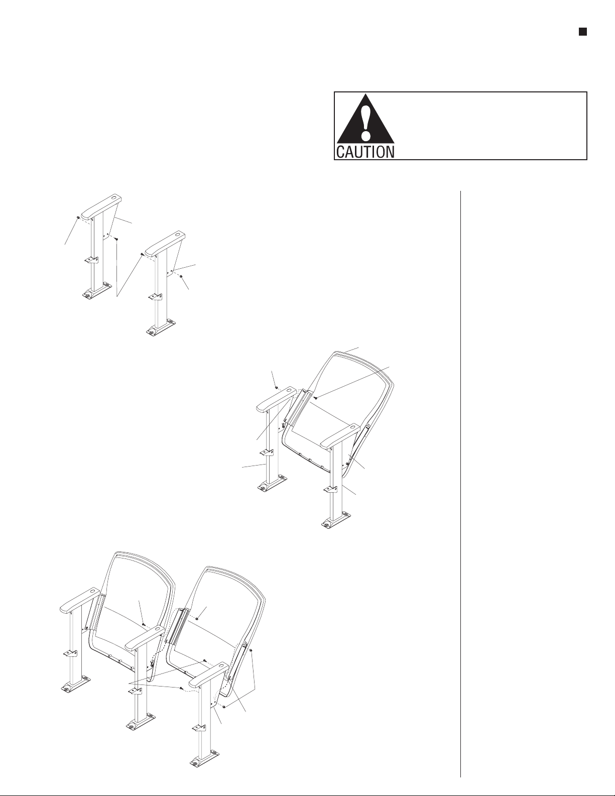
Assemble units as described herein only. To do otherwise
may result in instability. All screws, nuts and bolts must be
tightened securely and must be checked periodically after
assembly. Failure to assemble properly, or to secure parts
may result in assembly failure and personal injury.
Power & USB Module
Installation
Note: Power components should
be installed before the seats are
assembled.
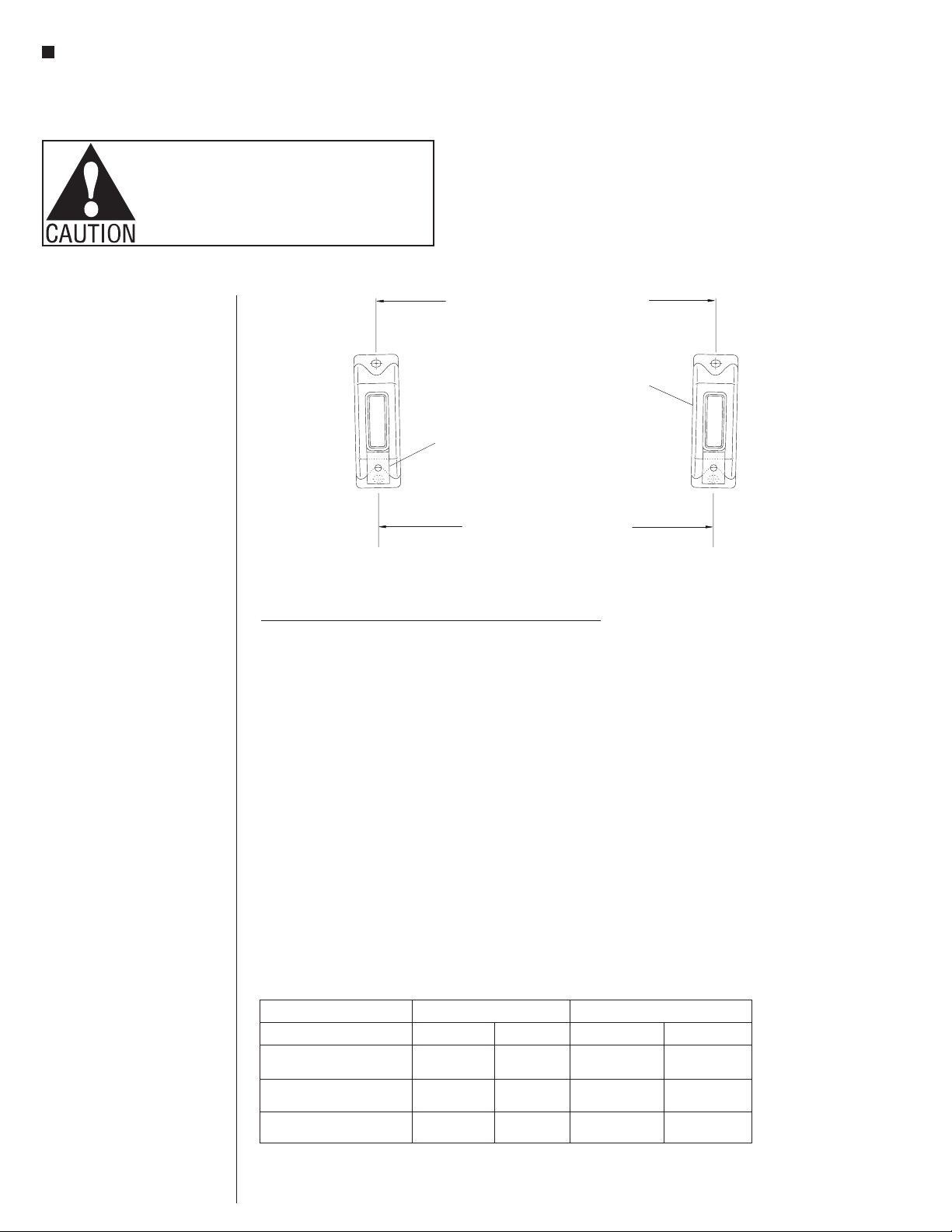
1. Secure the power & USB module
assembly to the module mounting
bracket using two #6 x 1/4” pan
head screws (Figure 6).
2. Secure the power & USB module
assembly with mounting bracket
to the top of the upright gusset
with two 1⁄4-20 x 5⁄8” Torx head
screws and two 1⁄4-20 acorn nuts
(Figure 6).
Note: If an end panel is attached
to an upright with a power & USB
module, the front screw of the
module mounting bracket will go
into the threaded insert in the
end panel.
Power Infeed Installation
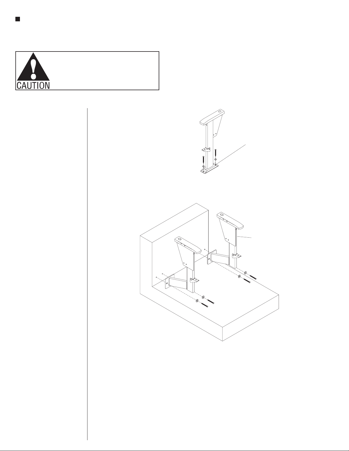
1. Orient and attach the power infeed
bottom bracket as illustrated, to
the foot of the upright using the
floor fastener bolt which secures
the upright to the floor (Figure 7
& Detail A).
2. Attach the top of the power infeed
outer box to the upright arm
gusset, and to the power infeed
bottom bracket below, using
1/4-20 x 5/8” Torx head screws and
1/4-20 acorn nuts (Figure 7).
3. Position the power infeed end
cover as illustrated up to the
installed power infeed outer box
and secure together using
1/4-20 x 5/8” Torx head screws and
1/4-20 acorn nuts (Figure 7).
4. Locate the power infeed harness
and components. Route the
8-wire end of the power infeed
harness through the 90° metal
connector and secure the
connector to the conduit end of
15
/ -20 x/”
torx head screws
48
#6 x/”
pan head screws
14
1
/ -20 acorn nuts
4
power & USB
module assembly
module mounting
bracket
Figure 6
power infeed
outer box
15
/ -20 x /”
Torx head screw
48
upright
arm gusset
power infeed
harness
5-wire
end
power infeed
bottom
bracket
quad connector
90° metal connector
floor
fastener
90° pulling elbow
liquid-tight
conduit
liquid-tight
connector
junction box
(not included)
#8 x /”
Torx head screw
3
8
1/ -20
acorn nut
4
power infeed
end cover
power infeed
inside cover
Figure 7
Detail A
4. Locate the power infeed harness and
components. Route the 5-wire end of the
power infeed harness through the 90-deg
metal connector and secure the connector to
the conduit end of the harness. Next run the
5-wires of the power infeed through the
power infeed inside cover and into, then out
through the corner opening of the 90-deg
pulling elbow. Twist the pulling elbow onto
the 90-deg metal connector over the power
infeed inside cover and tighten the jamb-nut
at the 90-deg metal connector side. Route
the 5-wires back into the corner, and out the
other side of the pulling elbow, then through
the liquid-tight connector, the liquid-tight
conduit and into the customer supplied
junction box. A certified electrician, following
all applicable state and local codes must
secure the components together and attach
the power infeed to building source power at
the appropriate time, verifying the electrical
integrity of the finished system (Figure 7).
Power Infeed Installation
5. Secure the power infeed inside cover to
the power infeed outer box using four #8 x
3/8” Torx head screws (Figure 7).
2. Attach the power infeed outer box to the
upright arm gusset at the top, and to the
power infeed bottom bracket below, using
1/4-20 x 5/8” Torx head screws and 1/4-20
acorn nuts (Figure 7).
1. Orient and attach the power infeed bottom
bracket as illustrated, to the foot of the
upright using the floor fastener bolt which
secures the upright to the floor (Figure 7 &
Detail A).
3. Position the power infeed end cover as
illustrated up to the installed power infeed
outer box and secure together using 1/4-20 x
5/8” Torx head screws and 1/4-20 acorn nuts
(Figure 7).
the harness. Next run the 8-wires
of the power infeed through the
power infeed inside cover and
into, then out through the rigid
conduit straight coupler. Twist
the coupler onto the 90° metal
connector, sandwiching the power
infeed inside cover and tighten
the jamb-nut at the 90° metal
connector side. Route the 8-wires
through the liquid-tight
connector, the liquid-tight
conduit and into the customer
supplied junction box. A
certified electrician, following all
applicable state and local codes
must secure the components
together and attach the power
infeed to building source power
at the appropriate time, verifying
the electrical integrity of the
finished system (Figure 7).
5. Secure the power infeed inside
cover to the power infeed outer
box using four #8 x 3/8” Torx head
screws (Figure 7).