manuals.online logo
Brands
  1. Home
  2. •
  3. Brands
  4. •
  5. KI
  6. •
  7. Indoor Furnishing
  8. •
  9. KI Balance User manual

KI Balance User manual

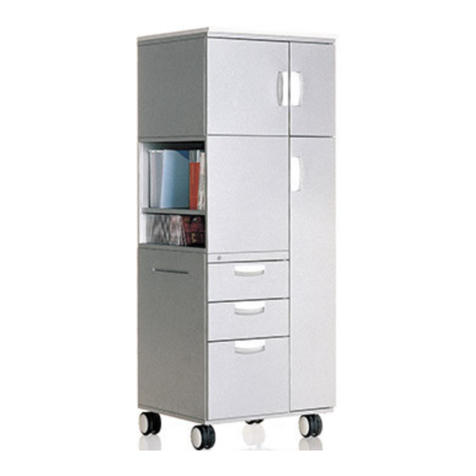
Assembly Instructions
Balance®Overhead Cabinet
December 2015
2
Assemble units as described herein only. To do otherwise
may result in instability. All screws, nuts and bolts must be
tightened securely and must be checked periodically after
assembly. Failure to assemble properly, or to secure parts
may result in assembly failure and personal injury.
Balance®Overhead Cabinet
Assembly Instructions
Mounting Bracket Attachment
Note: Mounting brackets for
different panel systems are attached
to the overhead in the same manner.
Depending on the panel system and
attachment type, a set of brackets
may consist of one left-hand and one
right-hand bracket or two
non-handed brackets.
1. Carefully set assembled overhead
on either end, on a soft surface to
prevent damage. Handed brackets
should be assembled so the toothed
flange of the mounting bracket
is flush with the overhead side.
Non-handed brackets should be
assembled so either end of bracket is
flush with the overhead side.
2. Engage the offset tab of the mounting
bracket into the slot along the back
of the overhead. Align the mounting
bracket hole with the hole in the
bottom of the overhead and fasten
with one 5/16-18 x 1/2” machine screw.
Repeat at the other end of overhead
(Figure 1).
3. Hang the overhead unit onto
the panel using the appropriate
mounting instructions for the system.
Note: An alternative installation
method may be used for overhead
units on all panel systems. Hang
the brackets onto the panel system
prior to attaching the brackets
to the overhead unit. Refer to
instructions of panel-mounted units
for information on attaching brackets
to panels. Hook the offset tab of the
bracket into the slot on the back of
the overhead, allowing the overhead
to fully engage the bracket. Align the
hole in mounting bracket to the hole
in the overhead bottom and fasten
with one 5/16-18 x 1/2” machine screw.
Repeat on other end of overhead unit.
Figure 1
mounting
bracket
hole
51
/ -18 x /
16 2
"
machine screw
On-Module
mounting
bracket
offset tab
overhead
cabinet
slot
overhead
side
Assemble units as described herein only. To do otherwise
may result in instability. All screws, nuts and bolts must be
tightened securely and must be checked periodically after
assembly. Failure to assemble properly, or to secure parts
may result in assembly failure and personal injury.
3
Balance®Overhead Cabinet
Assembly Instructions
On-Module Mounted
Overhead Units
1. The On-module mounting brackets
have integral teeth that engage the
vertical furniture hanging slots in the
panel frame. Locate the on-module
overhead unit at the height that is
desired on the panel. Engage the
upturned tooth of the top hook
(circled) into the panel frame by
holding the cabinetbottom out about
30°, then rotate the unit to engage
all the remaining teeth. When all
teeth are engaged, press down on the
cabinet to lock in place (Figure 2).
Caution: To remove the overhead
unit from the panel, push the bottom
of the cabinet straight up about 1/4”
and rotate the bottom out toward
you to about 30°. Pull the overhead
straight out and down. Do not force
the side panel, damage to the top
tooth may result.
Figure 2
on-module
overhead
upturned
tooth
On-Module
mounting
bracket
4
Assemble units as described herein only. To do otherwise
may result in instability. All screws, nuts and bolts must be
tightened securely and must be checked periodically after
assembly. Failure to assemble properly, or to secure parts
may result in assembly failure and personal injury.
Balance®Overhead Cabinet
Assembly Instructions
WireWorks®Off-Module Mounted
Overhead Units
1. WireWorks off-module overhead
units can only be hung with the top
aligned to a 12” high tile. To make
hanging the unit easier, remove the
top cap or tile directly above the top
of the overhead.
2. Disengage the overhead locks on the
mounting brackets by lifting the tabs
closest to the back of the overhead
and pulling it toward the cabinet.
With the overhead locks pulled out
toward the front of the cabinet, hang
the top and bottom of the mounting
brackets into the tracks of the panel’s
horizontal rail.
Caution: Make sure the cabinet is
hanging on the horizontal track and
not on the tile.
3. After the unit is hung in the track,
move it to the desired position by
gently lifting up while sliding it.
Secure the cabinet on the tracks by
pushing the overhead locks toward
the track (Figure 3).
Figure 3
12 tile"
mounting
bracket
overhead
lock
off-module
cabinet
Assemble units as described herein only. To do otherwise
may result in instability. All screws, nuts and bolts must be
tightened securely and must be checked periodically after
assembly. Failure to assemble properly, or to secure parts
may result in assembly failure and personal injury.
5
Balance®Overhead Cabinet
Assembly Instructions
Load Bar Mounted Overhead Units
1. To hang overhead units on a load bar,
rotate the bottom of the overhead unit
out approximately 30° and hook the
load bar mounting bracket onto the
top of the load bar. Rotate overhead
down until unit is secured in place
(Figure 4).
Note: Use the same procedure for
installing overhead units to load bars
on standard walls as with load bars
mounted to panel walls.
Figure 4
load bar
mounting bracket
load bar
load bar mounted
overhead unit
6
Assemble units as described herein only. To do otherwise
may result in instability. All screws, nuts and bolts must be
tightened securely and must be checked periodically after
assembly. Failure to assemble properly, or to secure parts
may result in assembly failure and personal injury.
Balance®Overhead Cabinet
Assembly Instructions
Upmount Bracket
1. Position brackets on a 54” high
WireWorks panel with the top tooth
(antidislodgement) engaged in
the sixth slot from the top of the
uppermost tile so there is a 43/4”
space between the top of the tile
and the top of the bracket. This will
position the bottom of the balance
cabinet at 20” above a 29” high
worksurface (Figure 5).
antidislodgement
tooth WireWorks
Panel
Detail A
Figure 5
upmount bracket
(right-hand)
upmount bracket
(left-hand)
Assemble units as described herein only. To do otherwise
may result in instability. All screws, nuts and bolts must be
tightened securely and must be checked periodically after
assembly. Failure to assemble properly, or to secure parts
may result in assembly failure and personal injury.
7
Balance®Overhead Cabinet
Assembly Instructions
Upmount Bracket-cont.
2. Carefully position Balance cabinet
on top of brackets, aligning the two
oblong slots of the bracket with the
threaded holes of the cabinet
(Figure 6).
3. Insert and tighten all four
5/16-18 x 3/4” screws.
WireWorks
Panel
Figure 6
53
/ -18 x /
16 4
"
screws
Balance
overhead cabinet
upmounting
bracket
8
Assemble units as described herein only. To do otherwise
may result in instability. All screws, nuts and bolts must be
tightened securely and must be checked periodically after
assembly. Failure to assemble properly, or to secure parts
may result in assembly failure and personal injury.
Balance®Overhead Cabinet
Assembly Instructions
Flexible WorkSpace™ Mounted
Overhead Units
1. The mounting bracket for Flexible
WorkSpace has a formed flange that
is hooked into an aluminum channel
at the top of each panel. These
flanges are offset to allow overhead
units to be hung from a panel in a
back-to-back manner (Figure 7).
2. Engage the flange of the mounting
brackets into the groove at the top of
the panel by holding the unit bottom
out approximately 30°, then rotate
down until unit is secured in place
(Figure 7).
Note: The 42” overhead unit is
the only size available for Flexible
WorkSpace and can only be hung
centered on a 44” panel.
Caution: The aluminum channel of
the Flexible WorkSpace panel must
be oriented at the top of the panel
prior to hanging any overhead.
Figure 7
aluminum
channel
Flexible WorkSpace
mounting bracket
Flexible WorkSpace
mounted overhead unit
Assemble units as described herein only. To do otherwise
may result in instability. All screws, nuts and bolts must be
tightened securely and must be checked periodically after
assembly. Failure to assemble properly, or to secure parts
may result in assembly failure and personal injury.
9
Balance®Overhead Cabinet
Assembly Instructions
Task Light Installation
1. Reference Figure 8 below to identify
the left- and right-hand brackets,
as well as four 8-32 x 1/4” tapping
screws within the bracket kit
(Figure 8).
Note: The electrical cord from the
task light must face to the rear of the
cabinet as illustrated when the task
light is installed.
2. One side at a time, position the
appropriate bracket as illustrated
(lever toward the center of the fixture)
to the task light unit and align the
mounting holes in the bracket with
the holes on the top of the task light
unit. Secure each bracket using two
8-32 x 1/4” tapping screws (Figure 8).
3. Before installing the task light to
the cabinet, insert the electrical cord
plug through the middle square
hole in the overhead trough back as
illustrated (Figure 9).
4. Hook the task light assembly
brackets into the slots in the
trough under the cabinet which are
appropriate for the size of overhead
unit and light (Figure 9).
Note: The length of the task light
does not have to match the size of
the overhead unit. Shorter lights may
be installed at the center point of the
cabinet or either side of center as
allowed by the slot locations.
5. After brackets are in place, rotate
levers on brakets upwards to lock the
task light in place.
6. Once the cord is routed
appropriately, plug it into a 120 volt,
60 HZ, grounded outlet. Excess cord
may be stored in the trough located
inside the overhead.
Caution: Be sure task light
assembly brackets are fully engaged
onto the overhead unit. Failure to
assemble properly or to secure parts
may result in assembly failure and
injury.
Figure 8
8-32 x /
1
4
"
tapping screw
left-hand
bracket
right-hand
bracket
lever
Figure 9
middle
hole
outside
hole
electrical
cord plug
Balance
overhead
cabinet
left-hand
bracket
right-hand
bracket
10
Assemble units as described herein only. To do otherwise
may result in instability. All screws, nuts and bolts must be
tightened securely and must be checked periodically after
assembly. Failure to assemble properly, or to secure parts
may result in assembly failure and personal injury.
Balance®Overhead Cabinet
Assembly Instructions
Tack Board & Tool Rail
Attachment Bar to Balance
Overhead with On-Module
Mounting Bracket
Note: Overhead units installed
to panel systems with on-module
mounting brackets may utilize a
tack board or tool rail which is
attached directly to the overhead via
an attachment bar assembled to the
overhead unit (Figure 10).
1. To install attachment bar to
on-module mounting bracket, locate
and loosen the two 5/16-18 x 1/2”
screws which attach the mounting
brackets to the underside of the
Balance overhead unit. Turn each
screw out about 1/8” to allow for
installation (Figure 10).
2. Orient the attachment bar as
illustrated, align the slots in the
attachment bar with the loosened
screws and slide into place.
Re-tighten the two screws to secure
attachment bar in place (Figure 10).
Tack Board & Tool Rail
Attachment Bar to Balance
Overhead with Load Bar Mounting
Bracket
Note: Overhead units installed
to panel systems using a load bar
mounting bracket may utilize a tack
board or tool rail which is installed
to an attachment bar. The attachment
bar is secured to the load bar
mounting bracket of the overhead
(Figure 11).
1. To install attachment bar to the load
bar mounting bracket as illustrated,
first twist in two 5/16-18 x 1/2” screws
at the location illustrated such that a
1/8” gap is left under the head of both
screws (Figure 11).
2. Orient the attachment bar as
illustrated, align the slots in the
attachment bar with the two screws
from step 1 and slide attachment bar
into place. Tighten the two screws
to secure attachment bar in place
(Figure 11).
Figure 11
Balance
overhead
load bar
mounting
bracket
51
/ -18 x /
16 2
"
screw
attachment bar
On-Module
mounting bracket
51
/ -18 x /
16 2
"
screw
attachment bar
Figure 10
Assemble units as described herein only. To do otherwise
may result in instability. All screws, nuts and bolts must be
tightened securely and must be checked periodically after
assembly. Failure to assemble properly, or to secure parts
may result in assembly failure and personal injury.
11
Balance®Overhead Cabinet
Assembly Instructions
Shelf Divider Installation
1. Orient the shelf divider as illustrated.
Place the shelf divider front hook into
the front slot of the overhead shelf.
Rotate the back of the shelf divider
down to engage it into the slot in the
overhead back (Figure 12).
2. To remove divider, reverse the above
steps.
Ganging Plate Installation
Note: When overhead units are
installed side-by-side on a panel
system, a ganging plate must be
installed between overheads to avoid
bowing of panel system.
1. Orient ganging plate as illustrated
under pair of overhead units and use
two 5/16-18 x 1/2” screws to secure
plate to underside of overhead units
(Figure 13).
Figure 13
ganging
plate
51
/ -18 x /
16 2
"
screw
panel-mounted
overhead units
Figure 12
back slot
front
shelf slot
shelf divider
front hook
KI
1330 Bellevue Street
P.O. Box 8100
Green Bay, Wisconsin 54308-8100
1-800-424-2432
www.ki.com
KI is a registered trademark
of Krueger International, Inc.
© 2015 Krueger International, Inc.
All Rights Reserved
Code KI-61172R3/KI/PDF/1215

Other KI Indoor Furnishing manuals

KI Uniframe Convertible Bench User manual

KI

KI Uniframe Convertible Bench User manual

KI Unite System User manual

KI

KI Unite System User manual

KI Toggle SS User manual

KI

KI Toggle SS User manual

KI Tattoo Chest User manual

KI

KI Tattoo Chest User manual

KI Aristotle Casegoods Conference Table User manual

KI

KI Aristotle Casegoods Conference Table User manual

KI Pirouette User manual

KI

KI Pirouette User manual

KI Concerto User manual

KI

KI Concerto User manual

KI Altus Installation guide

KI

KI Altus Installation guide

KI Trek User manual

KI

KI Trek User manual

KI Likha Casegoods User manual

KI

KI Likha Casegoods User manual

KI CrossRoads Shelving Single Face Metal with Back... User manual

KI

KI CrossRoads Shelving Single Face Metal with Back... User manual

KI FX User manual

KI

KI FX User manual

KI Tattoo Low Cupboard User manual

KI

KI Tattoo Low Cupboard User manual

KI WorkZone User manual

KI

KI WorkZone User manual

KI Vertical Cable Manager User manual

KI

KI Vertical Cable Manager User manual

KI WireWorks Base Raceway Center Support User manual

KI

KI WireWorks Base Raceway Center Support User manual

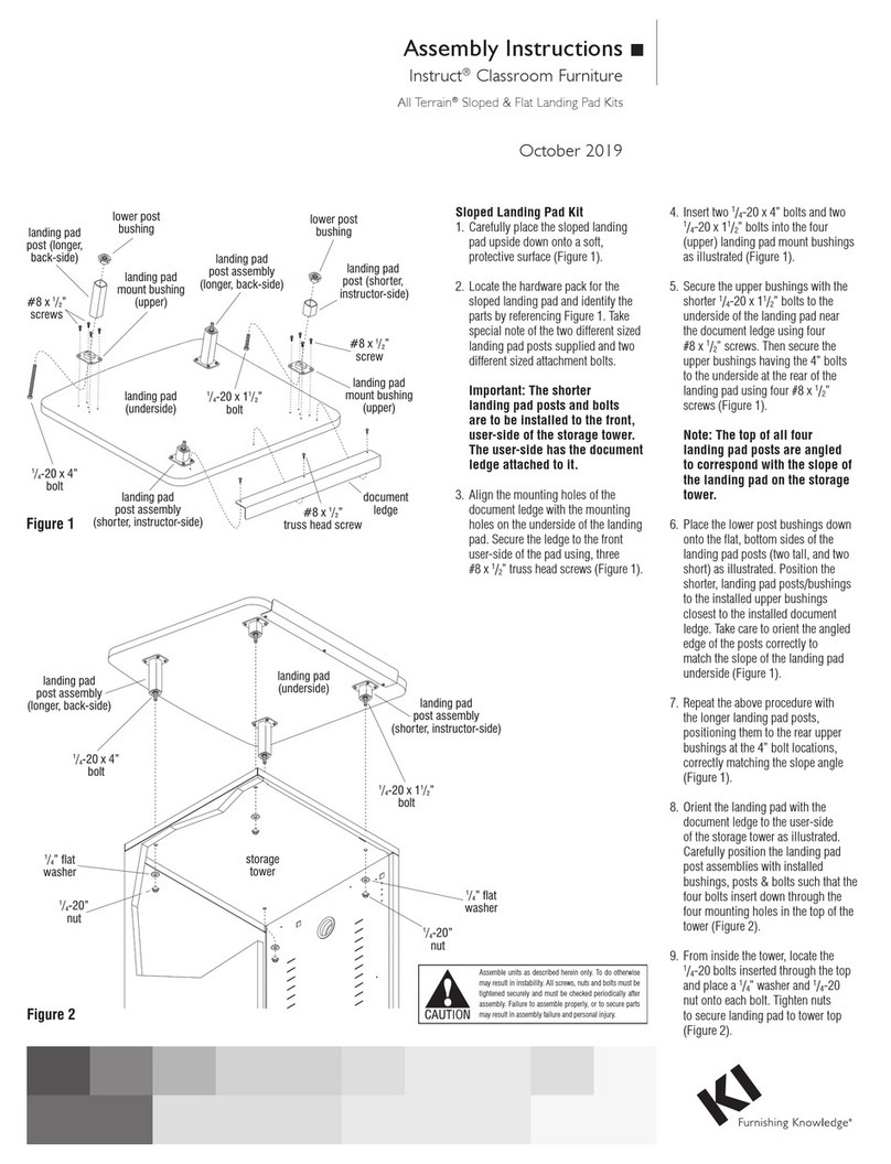
KI Instruct All Terrain Sloped Landing Pad Kit User manual

KI

KI Instruct All Terrain Sloped Landing Pad Kit User manual

KI Altus Task Seating Installation instructions

KI

KI Altus Task Seating Installation instructions

KI All Terrain Binder Tower User manual

KI

KI All Terrain Binder Tower User manual

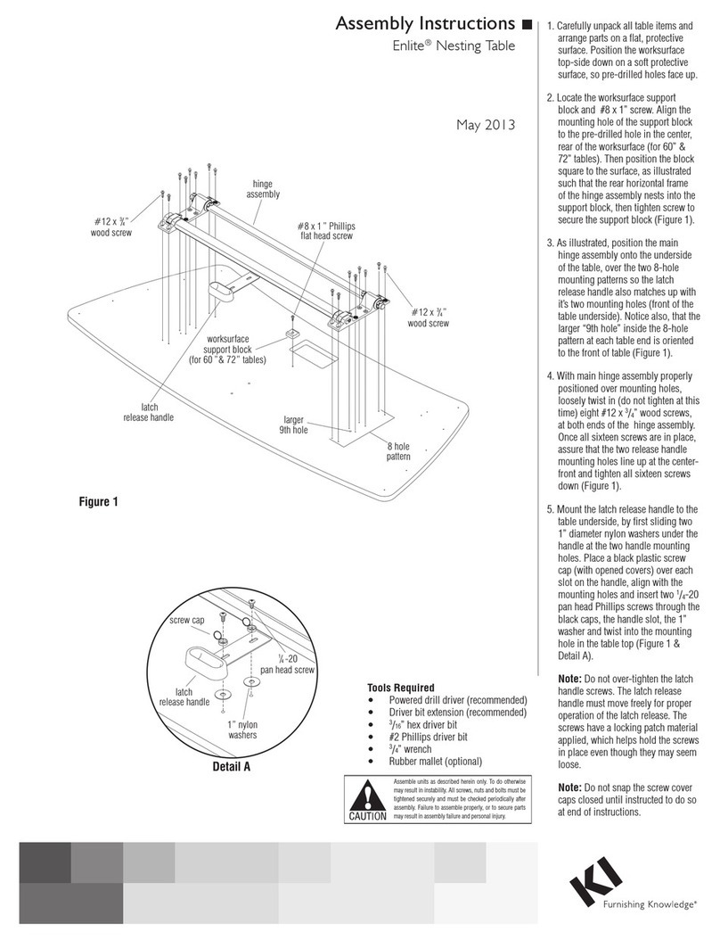
KI Enlite Nesting Table User manual

KI

KI Enlite Nesting Table User manual

KI Intellect Wave Chair Guide

KI

KI Intellect Wave Chair Guide

KI Inquire Table User manual

KI

KI Inquire Table User manual

KI Trek TT-Base Folding Table User manual

KI

KI Trek TT-Base Folding Table User manual

KI All Terrain Modular Storage Tower User manual
KI

KI All Terrain Modular Storage Tower User manual

Popular Indoor Furnishing manuals by other brands

Uplift Desk J3 CHR456 instructions

Uplift Desk

Uplift Desk J3 CHR456 instructions

Boraam FENTON 76024 Assembly instructions

Boraam

Boraam FENTON 76024 Assembly instructions

OkiOki Coastal Bed Instructional guide

OkiOki

OkiOki Coastal Bed Instructional guide

driade MERIDIANA 7310192 Assembly instruction

driade

driade MERIDIANA 7310192 Assembly instruction

Accentrics Home DS-D470-180 Assembly manual

Accentrics Home

Accentrics Home DS-D470-180 Assembly manual

Southern Enterprises MS998400TX Assembly instructions

Southern Enterprises

Southern Enterprises MS998400TX Assembly instructions

Wren 600 Assembly guide

Wren

Wren 600 Assembly guide

LINEA BRASIL Balcao com Painel Chicago Assembly instructions

LINEA BRASIL

LINEA BRASIL Balcao com Painel Chicago Assembly instructions

ofichairs Baron manual

ofichairs

ofichairs Baron manual

BLACK RED WHITE INDIANA JREG 1so/80 Assembly manual

BLACK RED WHITE

BLACK RED WHITE INDIANA JREG 1so/80 Assembly manual

ROBERTO FIORE Cabinets To Go SBA36 Assembly instructions

ROBERTO FIORE

ROBERTO FIORE Cabinets To Go SBA36 Assembly instructions

Uplift Desk SoCo manual

Uplift Desk

Uplift Desk SoCo manual

DURAVIT Vero VE 6414 installation instructions

DURAVIT

DURAVIT Vero VE 6414 installation instructions

Forte GNTT131-C275 Assembling Instruction

Forte

Forte GNTT131-C275 Assembling Instruction

Forte ATDS92411 Assembling Instruction

Forte

Forte ATDS92411 Assembling Instruction

HOMCOM 836-048 manual

HOMCOM

HOMCOM 836-048 manual

Steelcase Criterion 453 Series Assembly Directions

Steelcase

Steelcase Criterion 453 Series Assembly Directions

eliving FURNITURE COCO CCO-TV180-WHT Assemble instructions

eliving FURNITURE

eliving FURNITURE COCO CCO-TV180-WHT Assemble instructions

manuals.online logo
manuals.online logoBrands
  • About & Mission
  • Contact us
  • Privacy Policy
  • Terms and Conditions

Copyright 2025 Manuals.Online. All Rights Reserved.