Unite® Panel System - Panel Frame Assembly
Assembly Instructions
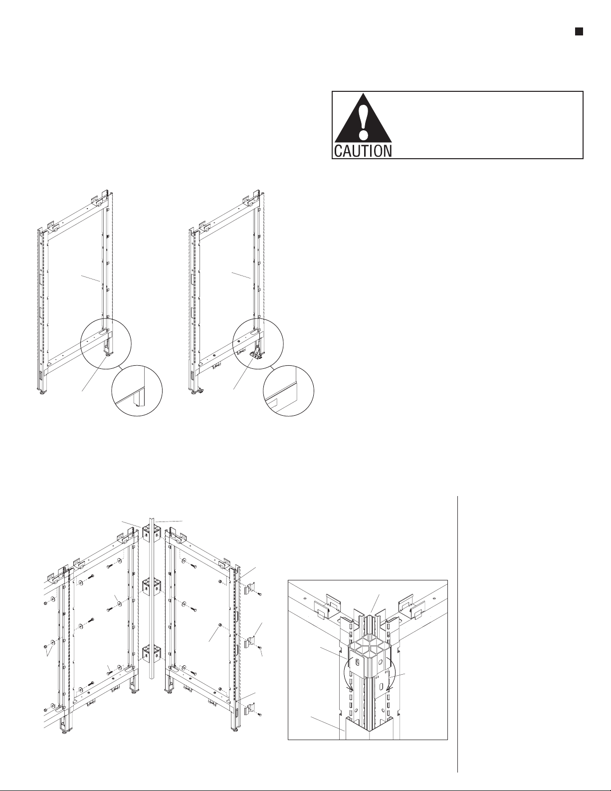
Assemble units as described herein only. To do otherwise
may result in instability. All screws, nuts and bolts must be
tightened securely and must be checked periodically after
assembly. Failure to assemble properly, or to secure parts
may result in assembly failure and personal injury.
9
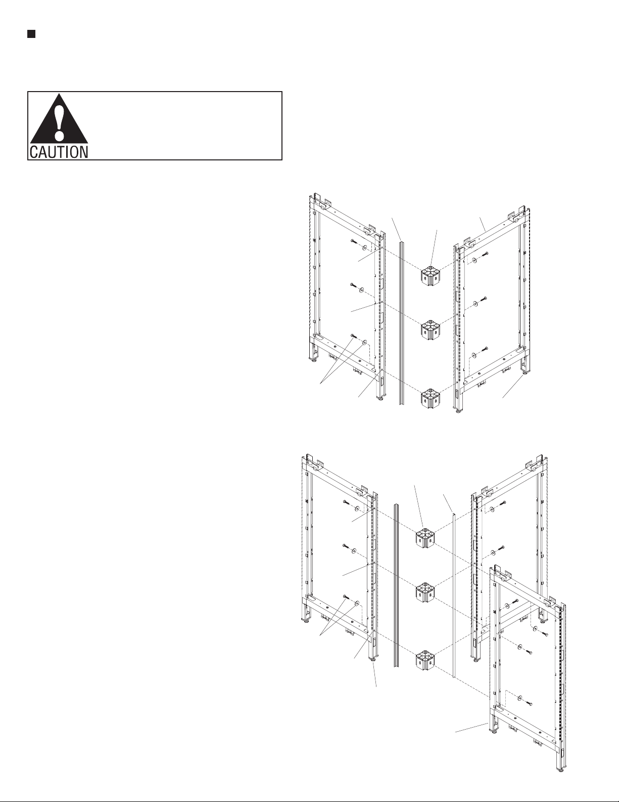
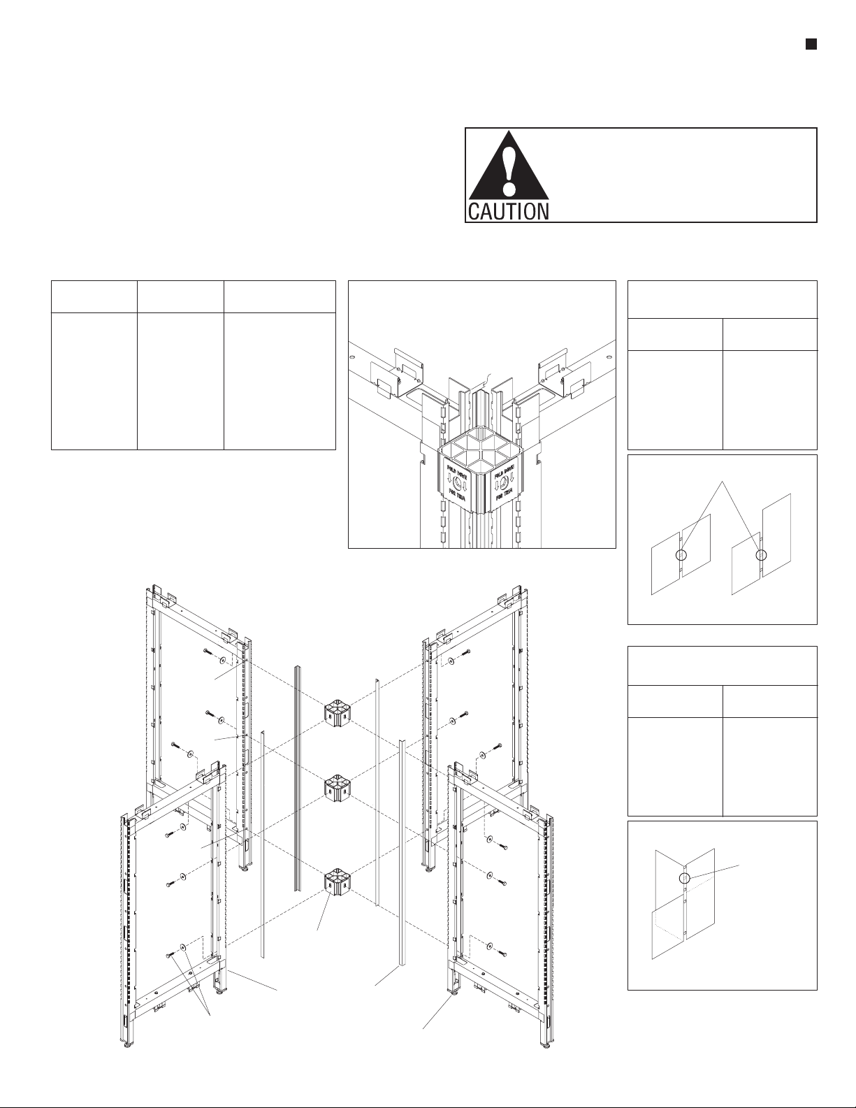
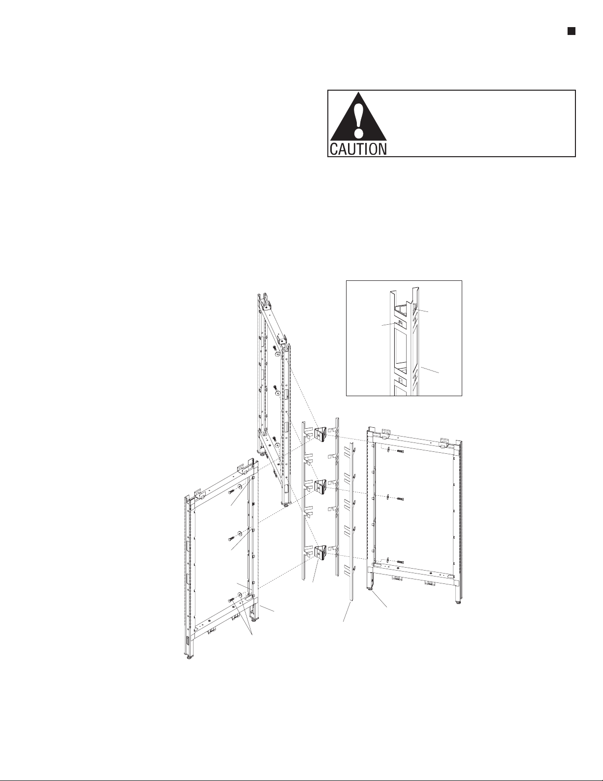
9-Stacking Sections (aluminum frame) -
Full-Height Intersection
31
/ -16 x 1 /
bolt
84
”
31
/ -16 x 1 /
bolt & washer
84
”
33
/ -16 x /
bolts
84
”
3/ -16
8
washer
connector
block
connector
block
(30 belt line)”
shield
vertical
stacking post
vertical
stacking post
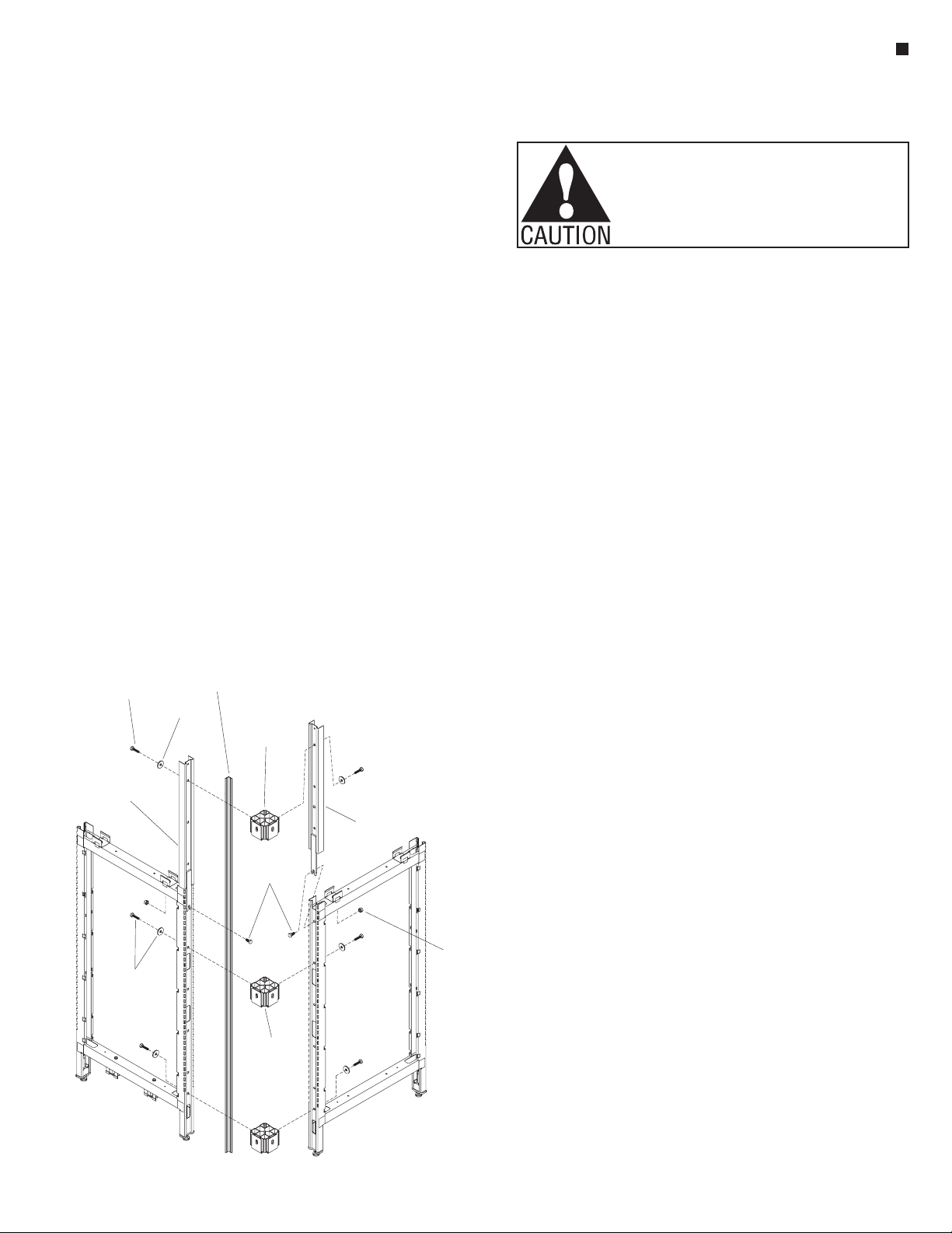
Stacking Sections (aluminum
frame) - Full-Height
Intersection Assembly
Note: Stacking sections -
full-height intersections are
specified/ordered at time of
original space planning and come
with full-height light shield,
full-height vertical intersection
trim and three connector blocks
as illustrated (Figure 9).
Note: Stacking sections with
"top frame" (aluminum frame)
are constructed of a four-sided
aluminum frame and contain
either glass, steel or perforated
steel inserts pre-installed at the
factory. they use separate vertical
stacking posts to hold the "top
frame" in place (Detail E,
page 13).
IMPORTANT: Reference
"Connector Block with Spacer
Plate Overview" on page 3, to
review the correct installation
procedure of connector blocks
to panel frame intersections
(Detail A).
Important: When stacking
sections are ordered after
original space planning/
installation, the light shield
and trim will ship in two
pieces to install in two pieces
(Page 69, Figure 4).
Note: If full-height vertical
intersection trim and
full-height light shield
(optional) are desired after
original space plan installation
instead of two-piece assembly,
proceed to "Stacking
Sections - Overview"
instructions on page 67,
to disassemble and install the
full-height intersection trim. The
steps below and Figure 9
above illustrate the full-height
stacking intersection connection,
as ordered at time of space
planning.
1. Install the vertical stacking posts
to the top of panel frames at the
intersection using 3/8-16 x 3/4”
hex head bolts and 3/8-16 k-lock
nuts (Figure 9).
Note: Three connector blocks
are required at every intersection.
2. Loosely attach connector blocks
on one panel frame and vertical
stacking post side. Each block is
secured using a 3/8-16 x 11/4”
hex bolt and flat washer. The
upper connector block attaches
at the top of the vertical stacking
posts, the middle connector
block near the 30” belt line and
the bottom connector block
mounts at the lowest mounting
hole of the panel frame. Note: If
the lower panel height is near the
30” belt line height, a connector
block/hardware can replace the
3/8-16 x 3/4” bolt and k-lock nut.
3. Attach the second panel frame
and vertical stacking post
assembly to the installed
connector blocks of the first
panel frame using 3/8-16 x 11/4”
hex head bolts and large flat
washers (Figure 9).
4. Tighten all 3/8-16 x 11/4” hex
bolts securing panel frames
to connector blocks at the
intersection. Tighten the
3/8-16 x 3/4” hex head bolts to
k-lock nuts, securing the vertical
stacking posts at the intersection.
Twist the height-adjustable glides
in or out to level the panel frames
(Figure 9).
Note: Light shields are available
in 48, 64 & 80” nominal lengths.
The above light shield lengths do
not require cutting when paired
with the same nominal height
panel frame.
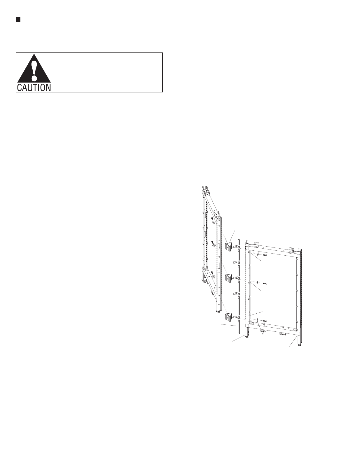
5. Begin light shield installation by
first locating the nominal length
plastic light shield that matches
the nominal height panel frame it
installs adjacent to. For nominal
height 32, 40 & 56” panels,
locate a light shield that is longer
than, but closest to the nominal
frame height. When required (for
32, 40 & 56” panel heights), cut
the longer plastic light shield to
size. See Detail A - “Light Shield
Table,” page 5 to determine
proper cut length.
6. Plastic light shields must be
installed after intersections are
assembled and all bolts are
tightened into connector blocks.
Measure and make a mark that
is 5/16” down from the top of the
vertical frame post (Detail B,
page 5). Using the proper length
light shield, position the top of
the shield at that 5/16” mark. Snap
the light shield into the corner of
each connector block such that
you hear a “click”, ensuring that
the light shield is snug at each
connector block.
Note: The bottom of the light
shield should fit flush with the
bottom trim when trim is installed.
The top of the light shield should
fit nearly flush with the underside
of an intersection top cap when it
is installed later.
Tip: A top cap can be temporarily
installed to help locate the top
of the light shield. Snap the light
shield in place such that the top of
the shield is flush with the bottom
of an installed top cap.
Note: Additional instructions for
preconfigured segmented panel
frames are covered later in this
manual. Reference "Stacking
Sections (aluminum frame) -
End-of-Run & In-Line Assembly"
instructions on page 13.